◎ Original Paper
ISSN (Print): 2287-9706
Design of a Pump-Turbine Based on the 3D Inverse Design Method
Chengcheng Chen * , Baoshan Zhu ** , Patrick Mark Singh *** , Young-Do Choi ****†
1)Key Words : Pump-Turbine(
펌프터빈), Impeller Design(
임펠러 설계), 3D Reverse Design Method(3
차원 역설계법), Performance(
성능) ABSTRACT
The pump-turbine impeller is the key component of pumped storage power plant. Current design methods of pump-turbine impeller are private and protected from public viewing. Generally, the design proceeds in two steps: the initial hydraulic design and optimization design to achieve a balanced performance between pump mode and turbine mode. In this study, the 3D inverse design method is used for the initial hydraulic impeller design. However, due to the special demand of high performance in both pump and reverse mode, the design method is insufficient. This study is carried out by modifying the geometrical parameters of the blade which have great influence and need special consideration in obtaining the high performance on the both modes, such as blade shape type at low pressure side (inlet of pump mode, outlet of turbine mode) and the blade lean at blade high pressure side (outlet of pump mode, inlet of turbine mode). The influence of the geometrical parameters on the performance characteristic is evaluated by CFD analysis which presents the efficiency and internal flow results. After these investigations of the geometrical parameters, the criteria of designing pump-turbine impeller blade low and high sides shape is achieved.
1. Introduction
Pumped storage power plant plays an important role in modern power grids. The electricity production from thermal power plants and nuclear power plants is maintained at a constant level and the amount is large, but the electricity consumption varies with the time period. Pumped storage is the best way to compensate for the gap between produced and consumed power.
Pump-turbine is the core equipment in pumped storage power plant which is characterized by rapid conversion between pump mode and turbine mode, comparing with the separate pump and turbine units
(1)
. In order to ensure the high performance in pumped water and generating power, the design of pump turbine must take into account both the pump efficiency and turbine efficiency.In this study, the initial impeller blade design is derived by applying an inverse design method based on a 3D potential flow approach. The 3D inverse design method has been widely used for the design of various kinds of turbomachinery, such as good performance Francis turbine and centrifugal pump
(2,3)
.The almost opposite hydraulic characteristic of pump and turbine are fulfilled in Pump-turbine impeller, thus the shape of pump turbine impeller blade can not be designed from a single aspect consideration
(4)
.To complete the design criteria, the shape of the blade is deeply considered by supplying different shape at the blade low pressure side and applying the stacking angle to define the blade lean at the blade high pressure side
(6,7)
. And the casing, vanes are designed with the consideration of flow condition in pump mode and turbine mode. The performance* Graduate School, Department of Mechanical Engineering, Mokpo National University, Mokpo
** Department of Thermal Engineering, Tsinghua University, Beijing, China
*** Graduate School, Department of Mechanical Engineering, Mokpo National University, Mokpo
**** Department of Mechanical Engineering, Institute of New and Renewable Energy Technology Research, Mokpo National University
† 교신저자(Corresponding Author), E-mail : [email protected]
Parameter(Unit) Value
N (r/min) 1200
Q (m 3 /s) 0.336
H (m) 32
D 1 (m) 0.445
D h (m) 0.135
D s (m) 0.264
L 1 (m) 0.051
Z 7
Table 1 Design specifications of impeller
Fig. 1 Sketch of impeller meridional shape
Fig. 2 Diameter distribution of the inscribed circle
prediction by CFD analysis is carried out by considering the efficiency and internal flow at both mode.
2. Design of pump-turbine model
For the initial blade design, the 3D inverse design method is used which is developed by Zengeneh
(5)
. In the 3D inverse design method, the blade shape is computed by a specified distribution of blade loading.The blade loading is specified by distribution of
∂(rVθ)/∂
m, which is the derivative of the angular momentumrVθ
corresponding to the meridional distance.For the incompressible flow, the relationship between the blade loading (
p + - p -
) and the derivative of the angular momentum is as following equation:
(1)
p +
: pressure on the blades pressure sidep -
: pressure on the blades suction sideZ
: number of bladeρ :
water densityW bl
: relativel velocity at blade surfaceV θ
: tangential component of velocityr :
radiusrV θ
: angular momentum(rV θ )/∂m
: the derivative of the angular momentum (also named the blade loading parameter)It is often convenient to use a curvilinear coordinate system (
m, s
) in the meridional plane, as sketched in Fig. 1. Herem
is the normalized length from low pressure side to high pressure side, named streamwise direction;m=0
corresponds to the low pressure side andm=1
to the high pressure side of the blade.Similarly,
s
is the normalized length from hub to shroud, named spanwise direction;s=0
corresponds to the hub ands=1
to the shroud. Note that them
ands
directions do not need to be orthogonal.2.1 Design of impeller
The pump-turbine impeller design specifications are shown in Table 1. The meridional passage shape was designed based on the pump design method, combination with the correction in turbine mode. The design strategy is to keep the same rotation speed for both modes and achieve different flow rates and heads
(4)
.The curvature of hub and shroud are constrained by a various inscribed circle. The diameter distribution of the inscribed circle (
D m
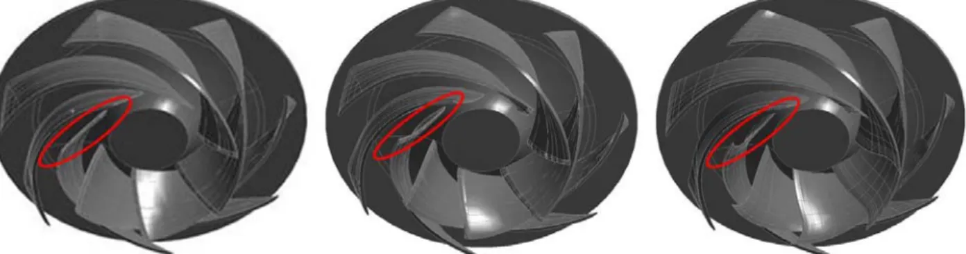
) in meridional passage is presented in Fig.2.Fig. 3 3 cases with different type of blade low pressure side shape
Fig. 4 Blade loading parameter distribution Fig. 5 Definition of stacking angle at blade high pressure side
2.2. Design of impeller blade shape
The blade loading can be modified by adjusting the blade loading parameters. Thus, the blade loading parameter is used as the design parameter. A typical parameter is used as the design parameter. A typical both the hub and shroud is shown in Fig. 4, which employs a combination of two parabolic curves and an intermediate linear curve in each distribution curve.
There are 4 parameters (
k
, slope of the linear segment;m 1
, interaction between the first parabolic section and the linear segment; m2
,interaction between the linear segment and second parabolic section;θ
, blade loading at leading edge) are needed to define a blade loading parameter distribution curve. Typical design of a blade by the use of 3D inverse design method needs the blade loading distribution at hub and shroud, thus eight parameters ([m 1 , m 2 , k, θ ] (s=0) , [m 1 , m 2 , k, θ] (s=1)
) are needed to design an integrated blade.The fore-loaded and after loaded designs are easily achieved by arranging the peak location of
∂(rVθ)/∂
min the forepart of shroud and the after part of hub respectively. The blade loading parameter distribution used for designing this impeller blade is shown in Fig.3.
In order to investigate the design criteria of pump-turbine impeller blade, a deep consideration is given to design the blade shape at the low pressure side and high pressure side.
2.3. Design impeller blade low and high pressure sides
2.3.1. Design of impeller blade low pressure side In this study, 3 types of shape are applied to the blade low pressure side, as shown in Fig. 3. The blade low pressure side is priority access to the flow when the impeller operates at pump mode. Therefore, the geometry of impeller blade low pressure side gives direct influence to the flow condition in the passage.
From the hub to shroud, the shape of blade low pressure side of case A is almost linearly stacking with
Fig. 6 Definition of stacking types
Stacking Types Case α λ
Zero stacking Case 1 0° 0°
Linear stacking_1
Case 2 4° 0°
Case 3 8° 0°
Case 4 10° 0°
Case 5 12° 0°
Case 6 16° 0°
Case 7 20° 0°
Case 8 24° 0°
Linear stacking_2
Case 1’ 0° 3°
Case 2’ 4° 3°
Case 3’ 8° 3°
Case 4’ 10° 3°
Case 5’ 12° 3°
Case 6’ 16° 3°
Case 7’ 20° 3°
Case 8’ 24° 3°
Table 2 The cases with different stacking angle
Fig. 7 Sketch drawing of casing, stay vane, guide vane
no curvature. Case B isdesigned with a small curvature at the intermediate segment of the blade low pressure side. These types of case A and case B are commonly applied in turbine runner blade, but the blade geometry of pump impeller is more similar to case C, with an extending shape at the shroud side and same curvature at the intermediate segment with case B. The three types of blade geometry are analyzed to investigate the influence caused by the blade low pressure side shape on the internal flow and performance of pump-turbine.
2.3.2. Design of impeller blade high pressure side In general condition of blade lean application, the determination of stacking angle in blade high pressure side only needs to meet the flow condition in one rotation mode, pump operation or turbine operation.
On the pump-turbine impeller design, the flow characteristic of pump mode and turbine mode are both important, thus, the design of blade lean for a pump turbine impeller is carried out by a more detail consideration of stacking angle at hub(α) and shroud (λ), as shown in Fig. 5.
In this study, a main research topic is the influence of stacking angle on the pump-turbine performance.
Three types of stacking angle at impeller high pressure side are designed, as illustrated in Fig. 6. Zero stacking: the stacking angle at shroud and hub are fixed with 0°, as the case 0 (α=0°, λ=0°); Linear stacking_1: the shroud is fixed in the coordinate axis, the stacking angle at hub are specified in various degrees, as the cases 1 to 8(α=x1, λ=0°); Linear stacking_2: the stacking angle at shroud and hub are both specified in degrees, as the cases 1′ to 8′ (α=x1, λ=3°). The complete cases for investigating the influence are listed in table 2.
2.4. Design pump-turbine casing and vane passages
Figure 7 shows the flow condition in pump-turbine system and the sketch drawing of casing and vanes.
Designing the casing, stay vane, guide vane for pump-turbine system, the flow direction in both pump mode and turbine mode should be considered.
Comparison with the common profile for uni- directional operation hydraulic machinery, the shape for pump-turbine system distributor is more inclined to symmetry at the leading edge and trailing edge. The number of stay vane and guide vane both are 20, and the relative location of stay vane and guide vane is shown as Fig. 7. In addition, the ending of casing is partitioned by using a stay vane, avoiding the flow in the casing ending and casing entrance interfere with each other.
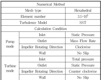
Numerical Method
Mesh type Hexahedral
Element number 3.1×10 6
Turbulence Model SST
Calculation Condition
Pump mode
Inlet Static Pressure
Outlet Mass Flow Rate
Impeller Rotating Direction Clockwise
Wall No Slip
Turbine mode
Inlet Total pressure
Outlet Static Pressure
Impeller Rotating Direction Counter clockwise
Wall No Slip
Table 3 Numerical methods and boundary condition
Fig. 8 Total calculation domain and numerical grid
Fig. 9 Hexahedral numerical grid of impeller
Fig. 10 Performance curve of pump-turbine
3. Numerical method
Computational Fluid Dynamic (CFD) analysis is a very useful tool for predicting hydro machinery performance at various operating conditions(8,9). For the designer, prediction of operating characteristics is the most important task. This study employs a commercial CFD code of ANSYS CFX(10) to conduct CFD analysis. The CFD analysis includes the volute, stay vanes, guide vanes, impeller and draft tube as total calculation domain. Each local domain of the pump-turbine is shown in Fig. 8. The grids of all domains include about 3.1 million element numbers, high density hexahedral grid is applied in the impeller domain as shown in Fig. 9. The average value of non-dimensional wall distance y+ of the impeller blade surface is less than 26.5.
The shear stress transport(SST) turbulence model is utilized, which has been well known to estimate both separation and vortex occurring on the wall of a complicated blade shape. The numerical methods and boundary condition are set as shown in Table 3. The general connection is between the rotational area and the fixed area in the flow field set as the frozen rotor condition.
4. Results and Discussion
4.1. Performance curves of pump-turbine
The curves in Fig. 10 give information about thepump-turbine system performance when it operates at pump mode and turbine mode respectively. The performance curves of turbine mode are investigated by fixed the head with vertical distance of the pump- turbine system upper and lower dam (H=32 m), adjusting the guide vane opening to obtain a performance curve including the operating condition of Partial loading, Normal and Excessive loading. The performance curves of pump mode are drawn by gathering the best efficiency point at every guide vane opening.
For the pump mode, the best efficiency (89.5 %) appears at the guide vane opening 31 mm, with flow
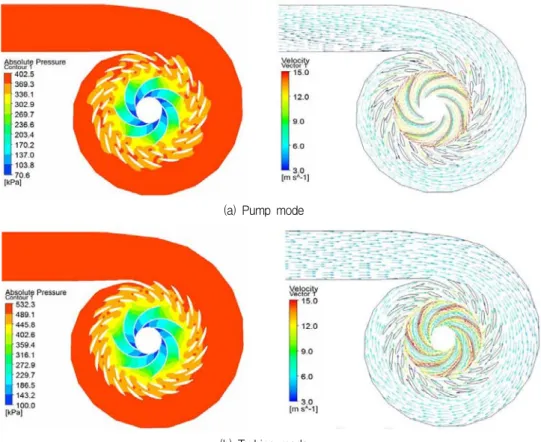
(a) Pump mode
(b) Turbine mode
Fig. 11 Pressure contour and velocity vector_Normal operating: (a) pump mode; (b) turbine mode
(a) Pump mode (b) Turbine mode
Fig. 12 Circumferential velocity distribution at impeller inlet and outlet_Normal operating: (a) pump mode; (b) turbine mode
rate 0.29 m
3
/s, head 33.13 m and power 104.9 kW, defined as normal operating. In addition, the partial loading and excessive loading are defined at the guide vane opening 15 mm and guide vane opening 39 mm in Fig. 10. The pump-turbine system can operates at a relatively high and nearly efficiency condition form partial loading to excessive loading, the corresponding efficiency change range is 84.54 – 85.02%.For the turbine mode, the performance curves present the best efficiency (92.6%) at the guide vane
opening 31 mm, with flow rate 0.28 m
3
/s, head 32.24 m and power 80.29 kW. At the partial loading of turbine mode, the efficiency decreases quickly, therefore, the performance characteristic of turbine mode at partial range is poor.Figure 11 shows the pressure contour and velocity vectors of pump mode and turbine mode at the best efficiency point. From the pressure contours, it is seen that the pressure increases gradually in both modes, no unusual pressure distribution is found from the
Fig. 13 Efficiency comparison of different blade shape at impeller blade low pressure side
Fig. 14 Efficiency comparison of different stacking angle at impeller blade high pressure side
impeller to the end of volute. Moreover, the velocity vectors of the turbine mode shows relatively good flow condition when the water flows through the volute, stay vane, guide vane and impeller. Comparing with the flow condition of turbine mode, the velocity vector of pump mode shows the water flows through the volute with a slight screw rotating tendency, which normally appears in pump and is acceptable.
Figure 12 shows the circumferential velocity of the impeller. vu1 is the circumferential velocity at impeller high pressure side,
vu 2
is the radius and circumferential velocity at impeller low pressure side, the plus or minus of ordinate in Fig. 12 corresponds to the rotational direction of the impeller. Almost zero circumferential velocity at the pump inlet and turbine outlet which means the energy converted by the impeller is maximum. In addition, the similar average value ofvu 2
at pump mode (12.07 m/s) and turbine mode (-12.85 m/s) indicates this impeller has similar ability of energy conversion when the impeller operates at pump mode and turbine mode. Further investigation by comparing fluctuation of circumferential velocity of pump mode and turbine mode indicates that the impeller is more stable when it operates at pump mode, proved by the relative small fluctuation of circumferential velocity at pump mode.4.2. Influence of different shape at impeller blade low pressure side
In cases A, B and C, the stacking angle at blade high pressure side is fixed with α=12°, λ=3° for
investigating of the influence of different shape at blade leading edge.
Figure 13 shows the efficiency obtained by different shapes of blade low pressure side. Comparing the efficiency of cases A, B and C, the efficiency change is relatively large at pump mode, 80.71 %, 88.13 % and 89.5% respectively.
In addition, the shape at blade low pressure side also gives influence to the turbine mode efficiency.
The best efficiency of turbine mode appears at case C, same as pump mode, but the efficiency change by blade leading shape is much smaller.
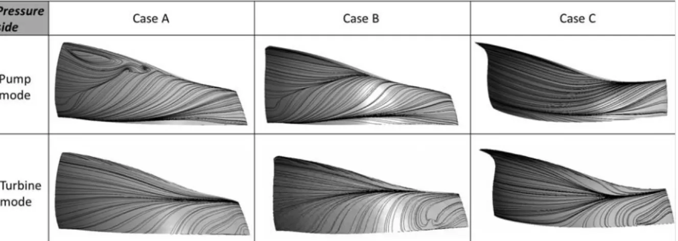
Due to the efficiency change at both modes, the further analysis of internal flow on both modes is carried out. Figure 15 shows the streamline distribution on the on the blade pressure side of both mode. In case A, relatively disordered flow condition is presented on the blade pressure side of pump mode, also showing the visible vortex and serious secondary flows.
Moreover, local secondary flow appears at blade surface of turbine mode.
The internal flow of pump mode is improved by applying the shape of Case B, where the visible vortex is eliminated and the local secondary flow on pressure side disappears. Case C shows a further improvement of internal flow at the pressure side of pump mode.
The secondary flow area is reduced and the flow distribution is more uniform. For turbine mode, the streamline shows no visible improvement of internal flow on blade surface according to the three types of shape in this study.
However, the secondary flow in the blade surface of
Fig. 15 Streamline distribution on the blade pressure side of both modes
Fig. 16 Velocity vector distribution at impeller passage (s=0.5)
both modes is not completely removed in case C, the optimization design of the blade shape will proceed in the next study.
4.3. Influence of different stacking angle at impeller blade high pressure side
In this section, the influence of stacking angle is examined by fixing the blade low pressure side shape with case C. Efficiency comparison of all cases with different lean angle are carried out and summarized by
the efficiency curves in Fig. 14.
With different stacking angle of shroud (λ=0° and λ
=3°), the efficiency curve shows almost similar values at turbine mode. However, the stacking angle at shroud make a difference in pump mode, reflecting on the obvious efficiency increase by changing the λ from λ=0° to λ=3°.
The abscissa axis in Fig. 14 presents the variation of stacking angle at the hub (from α=0° to α=24°). In the cases with fixed stacking angle at shroud (λ=0° or λ
=3°), the efficiency curve of turbine mode shows a
significant increase as α increases, then become stable at the end. The maximum efficiency of turbine mode (92.6%) appears at the stacking angle of α=12°, λ=3°.
The stacking angle at the hub gives small change to the pump mode efficiency according to relatively similar value of pump efficiency with variation of α.
The velocity vectors in Fig. 16 provide a further explanations to the efficiency variation in Fig. 14. In case 1, the stacking angle at hub and shroud are both designed with 0°, obvious secondary flow appears at impeller passage on both mode. In case 5, 12° is applied to stacking angle at hub, the secondary flow in turbine mode is eliminated but no significant improvement in pump mode is observed, agreeing with the visible efficiency increase in turbine mode rather than pump mode. The secondary flow in pump mode is removed by applying λ=3° to the stacking angle at the shroud, therefore the significant increase of pump mode efficiency appears on the condition of changing stacking angle of the shroud.
5. Conclusion
This study presents a pump-turbine design based on the 3D inverse design method and CFD analysis. The design of impeller meridional shape beginning from pump mode and the initial blade shape is computed by a specified distribution of blade loading.
Further investigation is proceeded by modifying the shape at blade low pressure side and applying different stacking angle at blade high pressure side, to examine the criteria of pump-turbine blade design.
The shape at low pressure side gives larger influence to the pump mode performance, the internal flow and efficiency are significantly improved by applying the shape of case C. However, the improvement of internal flow of turbine mode is not achieved according to the three types of blade shape in this study.
The stacking angle at the shroud (λ) removes the secondary flow in the impeller passage of pump mode and significantly increases the pump mode efficiency.
The stacking angle at the hub (α) gives major influence to the performance of turbine mode, the secondary flow in the impeller passage of turbine mode is eliminated and the maximum efficiency is obtained at α
=12°.
After these investigations of the geometrical parameters, the pump-turbine impeller is designed with the shape of case C at high pressure side and stacking angle α=12°, λ=3° at the trailing edge, achieves the best efficiency of 89.5% at pump mode and 92.6% at turbine mode. And relatively reasonable pressure and velocity distribution in the flow passage.
References