Manuscript received April 8, 2016, revised May 12, 2016, accepted June 1, 2016
Smart grid is called it as a system of systems. There are diverse types of systems in smart grid environment. Therefore, one of key factors to achieve smart grid successfully is interoperability among diverse systems. To secure interoperability, smart grid operating system should be developed complied with standards in terms of the data representation and communication. Common Information Model (CIM) and OLE Process for Control – Unified Architecture (OPC-UA) are the representative international standards in smart grid domain. Each standard defines data representation and communication by providing common information model and the unified architecture. In this paper, we explain a smart grid platform that we have developed to comply with CIM and OPC-UA standards for secure interoperability among numerous legacy systems.
Keywords : CIM, OPC-UA, platform, system integration, interoperability
I. INTRODUCTION
Smart grid environment is composed of various devices and systems including wind power, solar power, energy storage, smart meter, and electric automobiles and these coexist with diverse legacy systems involving power transmission and transformation operation, power distribution operation, new and renewable energy operation, and sales/demand operation systems.
Therefore, in order to implement a smart grid, it is necessary to ensure interoperability between a variety of device applications [1]. Interoperability can be realized with the application of standardized information model and communication architecture.
Recently, a Common Information Model (CIM) has been applied as a standard relative to the information model in the power field, while OLE Process for Control – Unified Architecture (OPC-UA) has been applied as communication architecture. CIM is an abstract information model that aims to model and express in the class form diverse types of information that occur in the power field, whereas OPC-UA is a communication architecture standard that describes how different types of systems or applications exchange information that is expressed as CIM [2][3].
In this study, CIM and OPC-UA-based integration platform technology is proposed that supports the interoperability of smart grid components by integrating various legacy systems that have been already in operation in the power field. In the integration platform construction process, a database was constructed through CIM modeling using data possessed by 12 legacy systems currently operated by Korea Electric Power Corp., and a standard based information model management system was implemented so that a system manager or a user is able to use the CIM model easily. Also, a standard based interface system was constructed that supports the CIM model for communication of information expressed as a CIM model on the basis of an OPC-UA standard.
The study outcome is being operated in the Gwangju and Jeonnam regions through a test and optimization process. This is valuable as the only smart grid integration platform that is
developed and operated directly in Korea, a single utility country.
Also this is meaningful in that the validity and efficacy of the study outcome has been proven not at an empirical level but through actual operations.
This paper is composed as follows: CIM and OPC-UA technology is explained briefly in section 2; information modeling results regarding how the CIM and OPC-UA technology was applied to this research project is shown in section 3; the design and development contents of an integration platform are explained in section 4; the efficacy of this platform is verified through diverse test cases and an optimization process is introduced in section 5; and, the conclusions and future research direction are described in section 6.
II. RESEARCH BACKGROUND: CIM & OPC-UA
A. Common Information Model
Power companies that operate a power system operate networks composed of a wide range of applications. During the operation process, a connection with various data such as actual power flow is made, and there is interoperability of the diverse systems or power facilities using these types of information. In the early 1990s, US power companies began research to enable the compatibility of communication models or data models that are subordinate to the data system of a supplier. Since then, there has been progress in the establishment of the IEC international standard in various fields including power generation, power transmission, power transformation, power distribution, and new
& renewable energy [4]. Among others, an information model
standard for integrating power system operation application is a
common information model, which is an IEC 61970/61968
standard. IEC 61970 is the standard for an energy management
system interface within a control center, whereas IEC 61968 is
the interface standard for power distribution management [5].
With the use of a common information model, power system resources can be expressed with classes and attributes, which facilitates connection between mutually independently developed systems and integration between application programs. The CIM primarily applied in this study comprises a set of complete packages, and the classes within a package have a correlation with classes in other packages as in Fig. 2. The CIM that has been defined to date is as in Table 1, and each application can utilize classes of a common information model from multiple packages.
The classification of a package does not mean classification of an application, and a random application can utilize entities of a common information model from multiple packages. The subordinate relationship between each of the packages with an IEC 61970 package diagram is shown in Fig. 1. A class has an attribute of explaining the characteristics of objects, and each class includes an attribute of explaining and identifying a specific instance of a relevant class. Each attribute has one type identifying the type of an attribute, and it is made up of types involving integer, float, Boolean, string, and enumeration and these are called prototypes. Besides, other additional types are defined as part of the specification of a common information model.
B. OPC-UA
OLE for Process Control (OPC) has been used widely in the industrial automation industry as an interface standard for ensuring the compatibility of different systems; however, the existing OPC ensures only interoperability within a local network and is limited in expressing abundant information as it is composed in a simple meta structure. Also, as it is subordinate to
Fig. 1. Diagram of IEC 61968 and 61970 packages [10][11].
Fig. 2. OPC-UA object model [12].
Table 1. Packages of common information model [10][11]
IEC 61970-301 IEC 61968-11
- Core - Domain - Generation - LoadModel - Meas - Outage - Protection - Topology - Wires - SCADA
- Common - WiresExt - Assets - AssetModels - Work - Customers - Metering - LoadControl - PaymentMetering
a specific language and platform, diversification in the industry caused difficult problems in dealing with the existing OPC and a new standard was demanded. OPC-UA was created to solve the aforementioned limitations of the existing OPC. It ensures the independence of a platform by introducing web service and a Service Oriented Architecture (SOA) paradigm to the existing OPC, which had been subordinate to a platform, and enables the expression of abundant information by reinforcing significantly an information model. Also, it reinforces security and expandability, which have been recognized as weaknesses in the existing OPC;
thus, it has become used widely throughout industries such as MES, and ERP. The OPC-UA object model (left) in Fig. 2 defines
the concepts, types, variables, and data type of objects, and it expresses the node and reference attribute as UML (Unified Markup Language). Meanwhile, an OPC-UA object (right) is composed of variables factors that are made up of value, quality attribute, timestamp attribute, methods factors that show movements operated by a client, and event factors that indicate an alarm to deal with an event in case of the occurrence of an event that requires serious attention.
The OPC-UA address space means a group of objects accessible from a server. The address space in an existing OPC is mutually independent. For instance, the current temperature value of a temperature transmitter is given through an UA address space
Fig. 3. CIM based component mapping of a main transformer.
Fig. 4. Main transformer class diagram [11].
whereas an alarm in accordance with temperature change is given an address space. However, address spaces in the current OPC- UA are mutually integrative. Accordingly, a developer is able to access the node and reference of an address space and to insert, add, change, and delete them through 10 service sets offered by OPC-UA during access to the node. Address spaces in classic OPC are mutually independent / Address spaces in OPC-UA are mutually integrated.
III. SMART GRID INTEGRATED PLATFORM INFORMATION MODELING
A. CIM based Information Modeling
In this study, CIM-based information modeling [6][7] is aimed at existing legacy systems operated by Korea Electric Power Corp. that comprise a power system, such as power transmission, transformation and distribution facilities, power consumers, new & renewable energy and energy storage, and power outage management systems. However, CIM is not quite full model to represent all kinds of equipment especially in case of renewable energy and energy storage. Therefore, as shown Fig.
4, we extend CIM (IEC61970: version 15, IEC61968: Version 11) to represent renewable energy and energy storage and some kinds of objects; switch, distribution line, FRTU, EES and so on.
Power transmission and transformation facilities are composed of substation facilities, while power distribution facilities are composed of diverse switches and pole transformers.
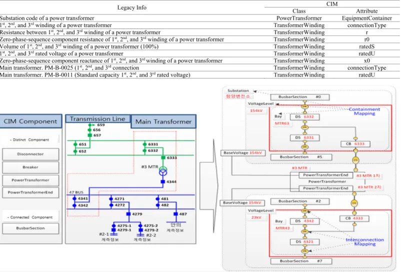
Power consumers are composed of energy consumers that are related with equipment that has a correlation with power distribution lines in the system including meter, location, metering, and customers. In this section, the CIM-based data modeling technique conducted in this study is explained through a modeling case of a main transformer (M.Tr) among power transmission and transformation facilities.
The main transformer facilities of power transmission and transformation are composed of the main body and transformer winding, tap changer, Circuit Breaker (CB), Disconnection Switch (DS), and Ground Disconnector (ES) devices, and each of the correlations and relevant common information components are as shown in Fig. 5. The M.Tr on the primary side 1, the disconnector of M.Tr on the secondary side, and a breaker are mapped as disconnector and breaker components, while the main body of the M.Tr is mapped as a power transformer, winding as a power transformer end, and tap changer as either a phase tap changer or a ratio tap changer component in accordance with use.
The main transformer information is expressed as the power transformer model class of IEC 61970. The correlation between the legacy system data regarding the main transformer class diagram, main transformer containment, and interconnection
Table 2. Main transformer CIM class modeling
Legacy Info CIM
Class Attribute
Substation code of a power transformer PowerTransformer EquipmentContainer
1st, 2nd, and 3rd winding of a power transformer TransformerWinding connectionType Resistance between 1st, 2nd, and 3rd winding of a power transformer TransformerWinding r Zero-phase-sequence component resistance of 1st, 2nd, and 3rd winding of a power transformer TransformerWinding r0
Volume of 1st, 2nd, and 3rd winding of a power transformer (100%) TransformerWinding ratedS
1st, 2nd, and 3rd rated voltage of a power transformer TransformerWinding ratedU
Zero-phase-sequence component reactance of 1st, 2nd, and 3rd winding of a power transformer TransformerWinding x0 Main transformer. PM-B-0025 (1st, 2nd, and 3rd connection TransformerWinding connectionType Main transformer. PM-B-0011 (Standard capacity 1st, 2nd, and 3rd rated voltage) TransformerWinding ratedU
Fig. 5. Main transformer containment and interconnection mapping.
mapping and the main transformer and the class of a common information model class are expressed in more detail as shown in Fig. 4 and 5 and Table 2.
B. CIM and OPC-UA Mapping
In order that diverse systems connected within a smart grid environment are able to communicate based on a standard
information model, it is necessary to combine the abstract information model (address space model) of OPC-UA and CIM.
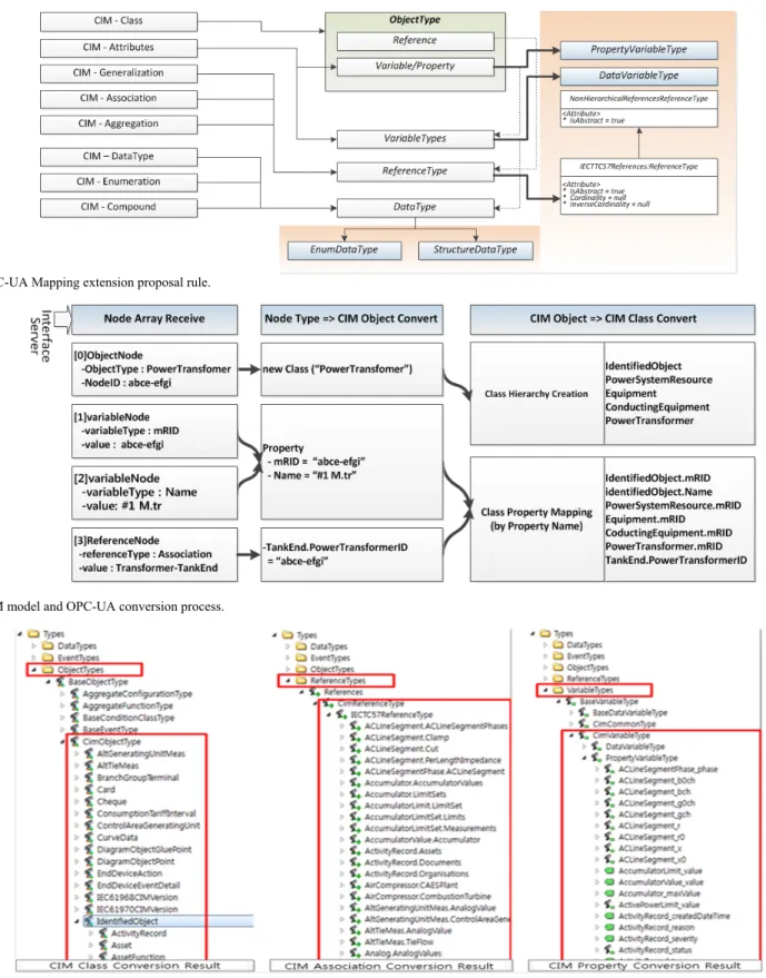
The CIM and OPC-UA mapping rules have currently proceeded with the standardization at IEC [8][9]. With a view to communicating a standard information model data based on CIM through the OPC-UA-based standard service, the CIM model should be mapped on the address space model of OPC-UA. In accordance with the IEC 61970-502-8 mapping standard, the
Fig. 6. OPC-UA Mapping extension proposal rule.
Fig. 7. CIM model and OPC-UA conversion process.
Fig. 8. CIM class, association, property conversion results.
CIM class is mapped as the object type of OPC-UA (Fig. 8, except for red part). The property and data type of the CIM class are mapped respectively as the variable type and data type of OPC-UA. In case of the CIM class, because only the class exposed as instance exists in the address space of OPC-UA, the variable type will exist only for actual CIM class property. The CIM association relationship is mapped as the reference type of OPC-UA. However, the basic mapping rule of IEC 61970-502-8 does not support sufficiently the property variable type, data variable type, IECTC57 references, reference type, enum data type, and structure data type of the CIM modeling; thus, an expansion rule was proposed in this study and this is shown as the red part in Fig. 8.
The process of transforming an OPC-UA abstract information model to CIM class using the above mentioned mapping rule is shown in Fig. 6. The OPC-UA abstract information model delivered from a client system by OPC-UA communication service is converted into the form of an object for converting each CIM model. The converted CIM object creates necessary classes by class hierarchy, which is a CIM schema, and is converted into each relevant mapped class property. The conversion of the CIM model into OPC-UA goes through an opposite procedure to the above-explained process, and Fig. 8 is a conversion result regarding CIM class, CIM association, and CIM property.
IV. SMART GRID INTEGRATED PLATFORM DESIGN AND DEVELOPMENT
A. SG Integrated Platform Design
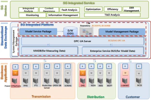
A smart grid integrated operation system is composed of an SG integrated platform and SG integrated service. An SG
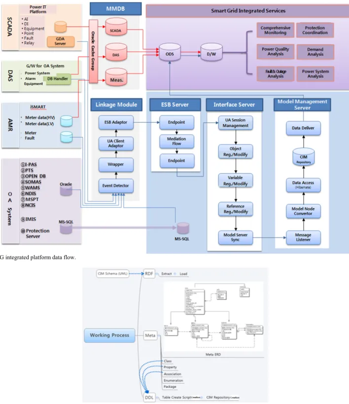
integrated platform is made up of a standard based information model management system involving CIM repository and DW and a standard based interface system. This collects data from connection modules (Wrapper (W) & Adaptor (A) in Fig. 9) installed in 12 types of legacy systems and plays a role of delivering information to an “SG integrated service” located at the upper part of the platform.
The red solid line in Fig. 9 is the entire structure of an SG integrated platform, and the two boxes drawn as red dotted lines express a standard based information model management system and a standard based interface system respectively. The key components of this platform architecture are a standard based information model management system (upper part) and a standard based interface system (lower part). First, a standard based information model management system comprises a model management package, which manages modeling information managed by a common information model (IEC 61970-301, IEC 61968-11); a model service package, which offers data service based on a common information model; and a system management package, which manages a standard based information model and interface. Herein, the model management package saves and manages schema defined in IEC61970 and IEC61968 CIM and modeling results, and information that becomes modeled through this is delivered to an OPC-UA-based standard interface server package by a model service package. The process is performed by a transaction manager who manages OPC-UA service included in a model service package and CIM transaction, a UA converter that converts the message of OPC-UA into a CIM- based transaction, and a message broker for exchange of interface server package and message. A standard interface server package is composed of a UA server SDK (software developer kit), which manages a service function with the OPC-UA standard and an address space; a UA stack, which transmits OPC-UA standard- based data; and service interface, which processes a service
Fig. 9. SG integrated platform architecture.
request of an OPC client.
B. SG Integrated Platform Development
With a view to standardizing data exchange between power information systems, power information systems should compose a message based on CIM, and this should be made through a common exchange method. For this, there is a need to convert all the data in power information systems that are already under operation to be CIM-based; however, in consideration of diverse factors including the replacement of the currently operated
system with a new CIM-based system or upgrade of its function, there is realistic difficulty. Accordingly, to make a CIM-based message transmitted and received and perceived while minimizing changes in existing systems, it should be composed so that it may replace the CIM message composition and transmission functions.
In order to enable this, it is necessary to construct a CIM-based DB that saves data retained by power information systems [13].
The DB can be constructed as follows. CIM uses as foundation technologies UML and XML, and it utilizes UML to indicate a correlation between the structure of an object and each of the objects. To exchange various meta data that were modeled with
Fig. 10. SG integrated platform data flow.
Fig. 11. Standard information model service DB construction procedure.
UML with data in a message form between applications, it should be converted into an XMI (XML metadata interchange) file form.
The XMI file created in this way produces a resource document framework file (RDF) by expressing reference and relationship by adding resource attributes to the factor data of XML through a CIM tool, an open source tool [8]. After parsing data from RDF schema created in this way, loading it on the CIM meta DB, and making an instance table by CIM class using the CIM meta information of loaded DB, it is necessary to construct the transmission, transformation, and distribution facilities, and customer information CIM instance DB. CIM modeling and a
modeling method between actual instances are not the topics of this paper; therefore, additional explanation is not provided. The above-mentioned conversion and storing process is shown in Fig.
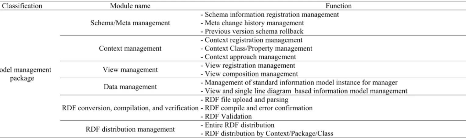
12, while Table 3 explains the modules and functions by each module possessed by a standard model management package to support the processes in Fig. 11.
As explained in former section, we developed a model service package and a system management package as well as a model management package during the development of a standard information model system. Each package plays the roles of schema meta model management, context model service, view information service, security management, and service log management; and detailed functions are as shown in Table 4.
A standard based interface system is composed of a standard interface server package and a client adapter. A standard interface server package is for mutual exchange of data expressed as a common information model based on OPC-UA. Meanwhile, a client adapter plays the role of detecting a change event that occurs in a legacy system while being loaded on a legacy connection module, converts detected data into a common information model (CIM), again converts it into the OPC-UA form, and transmits it into a standard interface server package.
SDK utilized for development of a standard interface server package in this study is Java Server/Client SDK by Prosys Co., and it is made up of a total of 5 modules including 3 modules involving a base module indispensable for an OPC UA server,
Fig. 12. Standard SDK architecture.
Table 3. Main functions of a model management package
Classification Module name Function
Model management package
Schema/Meta management
- Schema information registration management - Meta change history management
- Previous version schema rollback
Context management - Context registration management - Context Class/Property management - Context approach management View management - View registration management - View composition management
Data management - Management of standard information model instance for manager - View and single line diagram based information model management
RDF conversion, compilation, and verification
- RDF file upload and parsing - RDF compile and error confirmation - RDF Validation
RDF distribution management - Entire RDF distribution
- RDF distribution by Context/Package/Class
Table 4. Main functions of a model service and a system management package
Classification Module name Function
Model service package
Schema meta model service
- Offering schema version information
- Offering standard information model meta information - Offering Package/Class/Property information
Context model service
- Offering a context list and detailed information - Offering Context Class/Property information - Offering information regarding access to context View information service - Offering a view list and detailed information
- Offering view-based instance information by metric structure and type filter Instance In/Out service - Register/modify/delete standard information model instance
- Search standard information model instance
Model information node conversion service - Object node conversion of standard information model Class/Property, etc.
System management
package
Security management - Control system access by role and service - Manage system access account and security log Service log and statistics - Service access and event log
- Service statistics
Client standard interface adapter management - Manage components load and history for adapter composition - Upgrade the version of client adapter component
- Confirm the condition of client adapter Service management - Manage the current system resources
- Manage system resources use history
server driving control and server application module, and system integration. It is composed as shown in Fig. 12 and Table 4 [9].
V. TEST AND EVALUATION
A. SG Integrated Platform Test
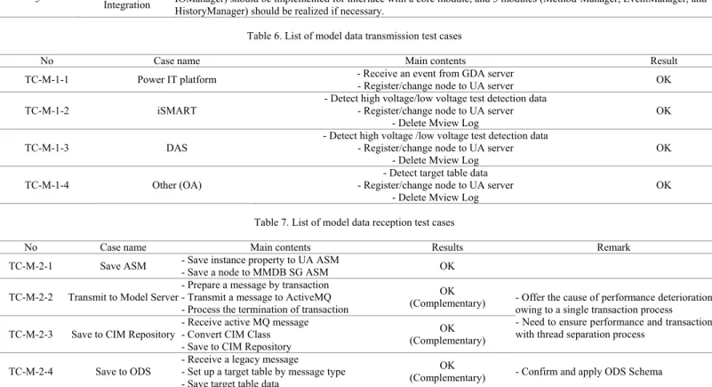
To test the efficiency of SG integrated platform functions and performances as mentioned in paragraphs 2 and 3, we set up a test section, prepared a test case, and conducted a test accordingly. If the test case by each section is indicated in accordance with an operation system environment, it is as in Fig.
13. The contents of a test case may be classified into cases of model data transmission and reception and cases of metric/
measuring/detection data transmission and reception. This is because given the character of metric/measuring/detection data that is created in large quantities and transmitted in a speedy cycle;
it was determined not to go through CIM and OPC-UA conversion at the level of platform performance improvement.
First, the test result of TC-M-q in Fig. 13 is a test case that tests the function with which data is delivered to the OPC-UA server by detecting data during the change of legacy data. Success
condition is designated as being that changed data that exist in a legacy system should be searched for as a node defined in the profile of a relevant type in UA address space; and, simultaneously, processed data should be cleared from legacy. The test result is as in Table 6.
The test result of TC-M-2 is a case of testing a function with which data is saved on an address space, CIM repository, or ODS by receiving data of a connection module. Success conditions are designated are being that the received data should be searched for as a node defined in the profile of a relevant type in an UA address space; and, simultaneously, received data should be searched on the relevant table of ODS. The test result is as in Table 7.
The test result of TC-R-1 is a case of testing a function with which detection/measuring/metric data are detected and received within a fixed cycle (time). Success conditions are designated as being that any change regarding high voltage/low voltage detection data should be reflected with a relevant cycle; and, simultaneously, any change concerning SCADA, AI/DI, or DAS measuring/metric event data should be reflected within a relevant cycle. The test result is as in Table 8.
This is a case for testing a function with which data is saved to an address space, CIM repository, or ODS by receiving the data of the TC-R-2 connection module. Success conditions are
Table 6. List of model data transmission test cases
No Case name Main contents Result
TC-M-1-1 Power IT platform - Receive an event from GDA server
- Register/change node to UA server OK
TC-M-1-2 iSMART
- Detect high voltage/low voltage test detection data - Register/change node to UA server
- Delete Mview Log
OK
TC-M-1-3 DAS
- Detect high voltage /low voltage test detection data - Register/change node to UA server
- Delete Mview Log OK
TC-M-1-4 Other (OA) - Detect target table data
- Register/change node to UA server - Delete Mview Log
OK
Table 7. List of model data reception test cases
No Case name Main contents Results Remark
TC-M-2-1 Save ASM - Save instance property to UA ASM
- Save a node to MMDB SG ASM OK
TC-M-2-2 Transmit to Model Server
- Prepare a message by transaction - Transmit a message to ActiveMQ - Process the termination of transaction
OK
(Complementary) - Offer the cause of performance deterioration owing to a single transaction process - Need to ensure performance and transaction with thread separation process
TC-M-2-3 Save to CIM Repository
- Receive active MQ message - Convert CIM Class - Save to CIM Repository
OK (Complementary)
TC-M-2-4 Save to ODS
- Receive a legacy message
- Set up a target table by message type - Save target table data
OK
(Complementary) - Confirm and apply ODS Schema
designated as being that received data should be searched as a node defined in the profile of a relevant type in an UA address space, and the received data should be searched in a relevant table of ODS. The test result is as in Table 9.
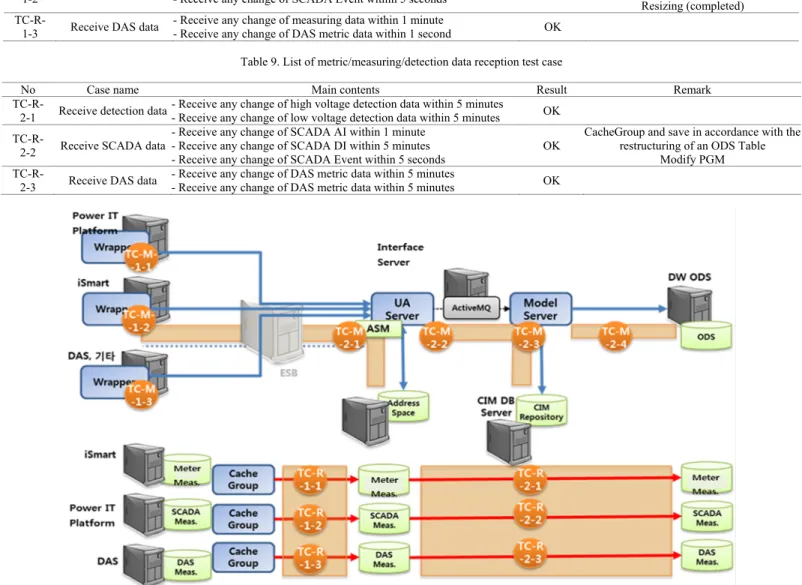
B. SG Integrated Platform Experimental Result
In this section, all the test results explained in former section cannot be depicted due to the page limit of this paper so we briefly explain TC-M-1-2 and TC-R-1-2 test results instead of all the test cases. Hence, we verify the efficiency of the 2 proposed approaches (see Fig. 10; linkage module approach, Oracle CacheGroup or MS Replica approach) for linking legacy systems based on CIM
& OPC-UA standards by measuring computing power (CPU usage, Disk I/O) of legacy system (iSMART) that the linkage modules we are developed. iSMART system is currently operating by Korea Electric Power Corporation. It manages customer and meter device and measuring data. As depicted in Fig. 10, we locate meter data (High voltage detection data, Low
voltage detection data) into MMDB in the SG integrated platform by using Oracle Cache Group for collecting meter data periodically updated considering performance. Moreover, in case of meter information and its fault information, we first, change legacy data as CIM & OPC-UA format and then, send them to SG integrated platform by means of linkage module that we developed according to the proposed approach explained in section 4.
The test results are shown at Fig. 14 and 15. At first, CPU is only used about 1% for sending meter device data in case of TC- M-1-2. In case of TC-R-1-2, only 9% of CPU usage occurs.
Moreover, in terms of disk I/O, notable results are not found caused by linkage module. Therefore, the proposed approach does not affect negative effects to legacy system for system integration based on CIM&OPC-UA standards
VI. CONCLUSIONS
In this study, to construct an information exchange system
Table 8. List of metric/measuring/detection data reception test cases
No Case name Main contents Result Remark
TC-R-
1-1 Receive detection data - Receive any change of high voltage detection data within 5 minutes
- Receive any change of low voltage detection data within 5 minutes OK - Fail to receive during a certain period owing to MDMS ODS server instability TC-R-
1-2 Receive SCADA data - Receive any change of SCADA AI/DI within 1 minute
- Receive any change of SCADA Event within 5 seconds OK
- Memory Full Error occurs -> MMDB Memory Resizing (completed) TC-R-
1-3 Receive DAS data - Receive any change of measuring data within 1 minute
- Receive any change of DAS metric data within 1 second OK
Table 9. List of metric/measuring/detection data reception test case
No Case name Main contents Result Remark
TC-R-
2-1 Receive detection data - Receive any change of high voltage detection data within 5 minutes
- Receive any change of low voltage detection data within 5 minutes OK
TC-R-
2-2 Receive SCADA data
- Receive any change of SCADA AI within 1 minute - Receive any change of SCADA DI within 5 minutes - Receive any change of SCADA Event within 5 seconds
OK
CacheGroup and save in accordance with the restructuring of an ODS Table
Modify PGM TC-R-
2-3 Receive DAS data - Receive any change of DAS metric data within 5 minutes
- Receive any change of DAS metric data within 5 minutes OK
Fig. 13. Test case by section.
among various systems in the power field of the future, the existing data of our company was modeled by applying a CIM based on the IEC 61970 and 61968 common information standards. Also a standard based information model management system that processes this in real-time was developed. In addition, an environment in which 12 legacy systems can be mutually operated was constructed by implementing a standard based interface system through applying the IEC 62541 OPC-UA communication architecture. Furthermore, we have proven that information exchange can be flexible and easy even in an environment composed of many more applications and systems by test-operating the SG comprehensive operation platform, the research outcome, in the Gwangju and Jeonnam regions. The SG comprehensive operation platform developed in this study is the largest platform in Korea. This is meaningful in that it reflects the international standard in the latest version, and it is the sole platform that has been applied in an actual power network operation environment.
Given the extensiveness and speed of change of smart grids, an integrated platform to be applied to a smart grid environment needs to double further the flexibility and expandability of the system itself so that any new service and application that are released rapidly in the market may be integrated flexibly.
However, there still remain many areas for improvement in the platform developed in this study until it can be extended and operated nationwide in terms of flexibility and performance. We are planning to construct an environment in which more diverse systems and applications can be operated mutually without technical, time, and cost issues by improving the real-time data process technology and expandability/flexibility of the integrated platform technology proposed through research into “Micro grid common platform technology development”, and this will be pursued for about 3 years up to 2018.
REFERENCES
[1] NIST, “Framework and Roadmap for Smart Grid Interoperability Standards”, 2010.
[2] Specht, Michael, and Sebastian Rohjans. "ICT and Energy Supply:
IEC 61970/61968 Common Information Model." Standardization in Smart Grids. Springer Berlin Heidelberg, 99-114, 2013.
[3] Lehnhoff, Sebastian, et al. "IEC 61850 based OPC-UA Communication -The Future of Smart Grid Automation." 17th Power Systems Computation Conference (PSCC 2011), Stockholm.
2011.
[4] IEC, Draft IEC/TR 62357 second edition: TC 57 Architecture - Part
Fig. 14. CPU usage and Disk I/O Performance Test Result of TC-M-1-2.Fig. 15. CPU usage and Disk I/O Performance Test Result of TC-R-1-2.
![Table 1. Packages of common information model [10][11]](https://thumb-ap.123doks.com/thumbv2/123dokinfo/4901208.291574/2.936.64.451.800.957/table-packages-of-common-information-model.webp)
![Fig. 4. Main transformer class diagram [11].](https://thumb-ap.123doks.com/thumbv2/123dokinfo/4901208.291574/3.936.149.810.321.852/fig-main-transformer-class-diagram.webp)