<연구논문>
582
Interactive 3D Pattern Design Using Real-time Pattern Deformation and Relative Human Body Coordinate System
In Hwan Sul
1), Hyun Sook Han
2,3), Yun Ja Nam
2), and Chang Kyu Park
3)1)
Korean Intellectual Property Office
2)
Dept. of Clothing & Textiles, Seoul National University; Seoul, Korea
3)
Dept. of Textile Engineering, Konkuk University; Seoul, Korea
실시간 패턴 변형과 인체 상대좌표계를 이용한 대화형 3D 패턴 디자인
설인환1)·한현숙2,3)·남윤자2)·박창규3)
1)특허청 섬유생활용품심사과
2)서울대학교 생활과학대학 의류학과
3)건국대학교 섬유공학과
Abstract : Garment design needs an iterative manipulation of 2D patterns to generate a final sloper. Traditionally there have been two kinds of design methodologies such as the flat pattern method and the pattern draping method. But today, it is possible to combine the advantages from the two methods due to the realistic cloth simulation techniques. We devised a new garment design system which starts from 3D initial drape simulation result and then modifies the garment by edit- ing the 2D flat patterns synchronously. With this interactive methodology using real-time pattern deformation technique, the designer can freely change a pattern shape by watching its 3D outlook in real-time. Also the final garment data were given relative coordinates with respect to the human anthropometric feature points detected by an automatic body feature detection algorithm. Using the relative human body coordinate system, the final garments can be re-used to an arbitrary body data without repositioning in the drape simulation. A female shirt was used for an example and a 3D body scan data was used for an illustration of the feature point detection algorithm.
Key words: real-time pattern deformation; relative human body coordinate system; drape simulation; anthropometric feature points;
1. Introduction
Historically, there have been two main streams of gar- ment design methodologies. The first one is the well known flat pattern method, which starts from 2D flat pattern with a priori experience of how the final garments will be shaped from the 2D patterns. The other one is the pattern draping method, which generates a garment by iterative shaping of an initial cloth on a manikin body. The former approach can be classified as a 2D-based method, while the latter one can be classified as 3D-based. The reason why the advan- tages of the two methods could not be used in the same time was that the simulation of garment was not feasible until recently. Unlike other engineering products made of metals, a cloth has a large deformation and it is very tricky
to predict its deformation. Thanks to the development of current computer hardware and software algorithms, fast 3D drape simulation is now possible and it has been widely used in 3D apparel CAD systems and computer anima- tions. This investigation implemented an interactive design methodology using a real-time cloth simulation and com- bined the advantages of the two traditional methods. Also the generated garment pattern data were recorded with a body relative coordinate system to re-use the garment data to an anonymous body without adjusting the initial posi- tions in the 3D simulation. An automatic body feature detection algorithm was developed to find the relative coor- dinate system for each body part. The theoretical back- grounds and explanation on the algorithms were described, followed by the test results for a female garment set.
2. Theoretical backgrounds
Our interactive design method is based on the real-time
Corresponding author; Chang Kyu Park Tel. +82-2-450-4196, Fax. +82-2-452-4186 E-mail: [email protected]
simulation of clothes. The idea is to modify the 2D pattern data and see the 3D draping result in the same time. There- fore it is essential to explain about the real-time cloth simu- lation technology. Researches on the prediction of a cloth deformation started with a continuum based approach using the finite element method (FEM) (Yu et al., 2000). Contin- uum mechanics originated from the mechanical engineer- ing where metals are used as a raw material. To predict the behavior of metals under tension, bending force, shearing force and torsion, a proper governing equation with bound- ary conditions and material properties should be defined first. The final governing equation leads to a linear matrix system and the deformation of the material under the given force condition can be known by solving the matrix equa- tion. The FEM is the famous method to construct and solve this matrix equation as it has a sound mathematical back- ground. Therefore such a continuum based methodology has become a standard for engineering analysis ranging from fluids to solids such as metals, plastics and concretes.
But the continuum based method has a weakness in the modeling of clothes. The main reason is that a cloth has a nonlinear and large deformation behavior even under a very small force. Moreover it has high in-plane stiffness from tensional rigidity while it has low out-of-plane bending rigidity. This stiffness becomes the cause of the numerical divergence. Application of the FEM to a cloth drape simula- tion was firstly tried by Yu et al. (Yu et al., 2000) and other research groups (Etzmuss et al., 2003) (Sze & Liu, 2007), but it is not practical for a garment design because the cal- culation cannot be done in a real-time and FEM has another shortcoming that it needs careful design of the mesh config- uration. Although it has an advantage that it generates a mathematically reliable result especially for the stiff clothes such as men’s suits, it cannot be said to be a proper tool for apparel designers. For apparel designers, computational efficiency is a more important factor than numerical exact- ness. So the particle based method was proposed as an alternative.
The particle based method (PBM) was initially used for the modeling of molecules and fluids, where the particles interact with each other. As their behavior is based on the vibration of particles, the PBM has a strong advantage that it can be effectively used for the modeling of large defor- mation materials such as a cloth because the resultant lin- ear system is easier to solve than that of the FEM and thus the calculation speed is faster.
But simply using PBM does not guarantee a stable and fast simulation of a cloth. Even if the PBM is used, the cloth is very easy to diverge during its simulation. This is due to the Courant condition that the safe time step is lin-
early constrained by the tensional stiffness especially when explicit Euler integration method is used. Baraff and Wit- kin (1998) was the first group who used semi-implicit inte- gration method to avoid the short time step problem from the explicit integration method. Using their method, a large time step of 33 ms can be used, while 10
-1~10
-3ms time step is used for the explicit integration (Oh et al., 2006).
But the shortcoming of their method is that the calculation of forces and their derivatives (Jacobian matrices) are very difficult to calculate. Such a complexity can lead to a slow calculation speed or even a divergence during the simula- tion. In this paper, we modified some of the Baraff’s for- mula to facilitate the calculation of forces and derivatives, to construct a real-time pattern deformation algorithm. The proposed algorithm was demonstrated with simulations of a female skirt and a shirt.
The other component that comprises drape simulation is the human body. As every individual has distinctive body sizes and shapes, garment patterns fitted to a specific body go to a wrong place in another body without modification in the initial positions. Therefore the patterns should be described with a relative coordinate system to body parts, not with a fixed coordinate system. Human body has a complex shape, so making a relative coordinate system for the whole body is not easy. Instead, each body part such as a head, a bodice, arms and legs have simple geometry simi- lar to a cylinder. So it seems reasonable to make a local coordinate system for each body part. But the human body data from a 3D scanner has no anthropometric information and it needs to be dissected to the six parts first. We imple- mented an automatic body feature point detection algo- rithm to recognize a human body from 3D scan data.
Detection of body feature points is needed to recognize the
shape of the body, deform the size parametrically and give
an animating effect. Nurre (1997) did an pioneering
research by dissecting a human body by finding a bisecting
cusp of a 2D body cross-sectional curve from a Cyber-
ware™ scanner. Dekkar et al. (1999) also used a slicing
method to detect feature points of the body and their
method was applied to a commercial system of
Hamamatsu™ scanner. Azouz et al. (2006) located land-
marks on the 3D human data from CAESAR project
recently. But the previous researches focused on geometric
interpretation of the body shape and generated only a sin-
gle rule, so they couldn’t cover a wide range of human
body shapes. We followed the same slicing based method-
ology but made decision tree based multiple detection algo-
rithm sets. Heuristic rules to find a suitable detection
algorithm for a specific body were constructed based on the
various body data of Koreans from SizeKorea project.
3. Algorithms
3.1. Interactive pattern design
Our algorithm is based on real-time cloth simulation engine. As the pattern designing is a repetitive work, the simulation speed is an important factor in our interactive design method. The speed of cloth drape simulation is com- posed of three components, which are a force/Jacobian cal- culation, a linear system solving and a collision detection/
response. To begin with, the equilibrium equation of a semi-implicit particle base method is
(1)
, where M is the n by n diagonal mass matrix whose diago- nal elements are m
0, m
0, m
0,m
1, m
1, m
1,…,m
n-1,m
n-1,m
n-1.(
m
iis mass of a particle i) and h is the time step. The force vector is 3n by 1 vector which is the summation of tension (f
t), shear (f
sh), bending (f
b) and other constraint forces (f
con).
(1
≤i
≤number of mesh vertices) (2) And the Jacobians ∂f/∂x and ∂f/∂v are 3n by 3n matrices whose 3 by 3 submatrices are from derivation of each force vector. By properly defining forces and Jacobian matrices, eq. (1) can be solved and the next position of cloth parti- cles can be known from ∆v (acceleration vector). In Bar- aff’s work, the tension was defined from the tension condition function C
tof a triangle, i.e.
(3)
, where a is the area of the triangle. As energy is (k
t=elastic constant), the tensile forces for triangle vertex i are
(4)
(5)
The constants b
uand b
vdetermines the warp/weft direc- tion shrinkage with default values of 1. Values below 1 shrinks the cloth and vice versa. This force term has an advantage that the global pattern shrinkage can be con- trolled in warp or weft directions, which are the basic local
axes of garments. But it has also a disadvantage that the calculation is lengthy and the patterns cannot be modified locally. Thus this force is suitable for a global pattern resiz- ing such as elastic bands of training wears.
In this investigation, pattern shapes should be able to be deformed locally, not globally. For this purpose, edge lengths of the cloth mesh should be controllable. So we used an edge based tension force term such as the following,
(6)
where x
ijis the edge between particle x
i, and x
j, and l
0is the initial length of it. The l
0is a local value, so we can control the length of an edge independently on other edges.
Our idea is that when the 2D flat patterns are deformed, the l
0’s of edges are changed simultaneously so that the 3D drape simulation can be affected.
Once the force and Jacobians are calculated, linear sys- tem of eq. (1) is constructed and it should be solved at each time step. The system can be solved with any kind of exact methods such as Gauss elimination or LU decomposition, but they cannot achieve a real-time speed due to a heavy amount of computation. Instead, conjugate gradient (CG) method (Shewchuk, 2002), which is an iterative method, was used. The CG method finds the solution generally less than in 20~30 iterations and it is much faster than exact methods. Note that the left-hand-side of eq. (1) is always positive definite, which means that it is always symmetric matrix. So only the upper diagonal Jacobians were recorded for fast calculation.
Lastly, the collision detection and response procedure is the most time-consuming step in a cloth simulation. The collisions can be classified as cloth-to-body collisions and cloth-to-cloth (self) collisions. Both types of collisions are basically checked by the collisions of triangle-to-triangle or triangle-to-vertex, but actually the time bottleneck is to find the collision candidate triangles, i.e. finding out which two triangles will collide. To reduce the number of collision candidates, it is important to skip non-penetrating triangle pairs in advance. So the clothes and body meshes were con- verted to a hierarchy of simple geometry such as discrete orientation polytopes (k-DOP) (Klosowski et al., 1998). k- DOP is a generalized axis aligned bounding volume and it is simpler to check the collisions of two k-DOP’s than checking the collisions of triangles. Only the triangle pairs whose k-DOP’s collided were checked in the actual colli- sion detection step.
M h ∂f
∂v---
– h2∂f
∂x---
⎝ – ⎠
⎛ ⎞ ∆v h f0 h ∂f
∂x---v0
⎝ + ⎠
⎛ ⎞
=
f0 fi (fii+fish+fib+… f+ icon)
∑
i=
∑
i=
Ctx a wu( )x –bu wv( )x –bv
⎝ ⎠
⎛ ⎞
=
E( )x kt
----2C x( )TC x( )
=
fi t ∂Eit
∂xi
--- k∂Cit( )x
∂xi
--- C⋅ it( )x –
= –
=
∂fi
∂xj
--- k ∂C x( )
∂xi --- ∂C x( )T
∂xj
--- ∂2C x( )
∂xi∂xj ---C x( )
⎝ + ⎠
⎛ ⎞
–
=
ft kt( xij –l0) xij xij ---
=
∂ft
∂xj
--- kt( xij –l0) xij
---I33 kt l0 xij
---I33xij⋅xijT xij 2 --- ∂ft
∂vj
---=0 , +
=
3.2. Anthropometric feature point based relative coor- dinate system
The conventional 3D apparel CAD solutions generally have only a few body data and the garments are generated with respect to the default bodies’ size and shape. But in an internet-based online apparel marking system (Park et al., 2007), the garment data should be applicable to anony- mous person’s body. Therefore the initial position of gar- ment patterns should be described by relative coordinates with respect to human body parts. An automatic body fea- ture detection algorithm was implemented to construct a relative coordinate system.
The raw data was acquired from Hamamatsu 3D body scanner, but the specific kind of scanner does not matter if only it generates point clouds successfully. The raw mesh data were converted to point clouds by slicing them in the height-directional planes (Dekker et al., 1999). The feature points were detected in two-steps heuristically. At the first step, terminal points such as a crotch, armholes, head tip, foot tips and hand tips were found. And then the other fea- ture points were found based on curvature changes in the second step. Cylindrical local coordinates were constructed for each body part such as head, bodice, arms and legs.
4. Methodology
4.1. Specification for drape simulation
We implemented the standard method of Baraff and Wit- kin (1998)’s semi-implicit version of PBM and increased the collision detection speed by preparing the collision detection information in advance(Sul, 2010). The final large sparse matrix which is generated by PBM was solved by an iterative method of conjugate gradient method, which is the time consuming step of PBM. The iteration stopped always less than 20~30 times and the simulation speed was 25 frames per second for 3 thousand triangular mesh vertices (excluding collision detection time). The collision detection level can be adjusted from fastest (triangle-to-vertex test) to slowest (Triangle-to-triangle test) depending on the colli- sion situation. All the implementations were written in C++
language in Codegear C++Builder 2007 at Pentium 4 dual core 3.0 GHz PC. We didn’t use any other external com- mercial software at all.
The validitation of drape simulation algorithm should consider not only the calculation speed, but also the exact- ness in which the material properties are expressed. To our disappointment, there is no exact material properties and real cloth specimen pairs which can test the validity of the drape simulation engines until now. Commercial softwares have their own material property parameters and the param-
eter values are different among companies. So we cannot measure the exactness of material property expression of our method exactly, but we can show the relative material property change visually instead. Table 1 shows the default material properties used in this investigation, which are similar to values of a general cotton cloth. The result for various material properies are shown in the chapter V.
3.3. Data for interactive pattern design
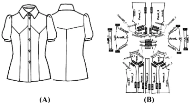
As an example of the interactive design method, patterns of a female shirt (ID#89) obtained from the garment pat- tern DB of Korean sewing technology institute were used.
Figure 1 shows the technical flats and DXF pattern data of the test shirt. The virtual garment can be simulated from the DXF pattern data or by using our interactive designing method.
3.4. Data for relative human body coordinate system To convert the raw 3D body scan data to a useful para- metric avatar, we used serial-sectioning method of point clouds and detected the anthropometric feature points which as extreme curvature change (Han, 2006). The raw 3D body scan data was acquired from Hamamatsu body scanner, but our method is applicable to any kind of body data even if the noises can be filtered in advance. The raw data has 140,763 vertices and 281,732 triangular elements in text file in the case of the body in Figure 7. We exported the file
Table 1. Default material properties of the fabrics used in the simulationProperty Value
Elastic constant kE (gf/cm) 1e6
Shear modulus (gf/cm) 1e5
Bending rigidity (gf cm2/cm) 0.01
Density (g/cm2) 0.1
Fig. 1. Pattern data of the test female shirt (ID #89) (a) technical flats (b) DXF pattern data withsewing information
format to conventional .OBJ or .3DS in the Hamamatsu software and used the .OBJ file for simplity’s sake. The anthropometric body feature points were acquired from the heuristically constructed procedures and decision tree shown in Figure 2. The decision tree was constructed from the scan data database of 100 males and 100 females of age 20~69 selected from SizeKorea project.
Once the anthropometric feature points are known, the bone points were found using the feature point information and texture/motion data were given from the ready-made avatar data (Sul & Kang 2010). The regenerated avatar can have any motion like cat-walk because it now contains motion skin data. To make each avatar to share a general coordinate system, each body part such as head, arms, legs and bodice were dismembered and assigned cylindrical coordinate system composed of radius, theta and z-coordi- nate as shown in Figure 2. Now the body parts have the
same relative coordinate system independent on their spe- cific orientation and sizes. Table 2 shows the lower and upper center points of cylindrical coordinate system of each body part. Figure 3 shows the structure of cylindrical coor- dinate system of a right arm, where the right hand tip and right shoulder point were used as a lower and an upper cyl- inder center respectively.
4. Results and Discussion
4.1. Verification of drape simulation algorithm
To show the validity of the proposed method, the prelimi- nary and necessary step is to show the validity of the drape simulation algorithm. Our drape simulation algorithm is based on the Baraff and Witkin (1998)‘s semi-implicit parti- cle based method which has been the standard method for garment simulation and has been used in almost every com- mercial computer graphics softwares such as FxGear’s Qua- loth (2004), Maya’s nCloth (2010) and 3D apparel CAD tools such as CLO Virtual Fashion’s Marvelous (2009) and Browzwear’s v-Stitcher (2000). Among the various imple- mentations, Marvelous (2009) shows the fastest speed by using multi-grid method based on Oh et al.(2006)’s paper and its speed is as fast as 30 frames per second for a 3
Fig. 2. Decision trees for an automatic feature point detection (a)flowchart of overall feature detection (b)
Detailed view of deci- sion tree based search rules for waist and abdomen points
Table 2. Center points for cylindrical coordinates of body parts
Body part Lower center Upper center
Head Neck center Head tip
Bodice Hip center Neck center
Left arm Left hand tip Left shoulder Right arm Right hand tip Right shoulder
Left leg Left ankle center Left hip center Right leg Right ankle center Right hip center
Fig. 3. Illustration of cylindrical coordinates for body parts
thousand mesh vertices. Our method didn’t include the multi-grid technique but optimized the collision detection method by preparing preliminary collision detection infor- mation in each matrices of triangular mesh elements (Sul, 2010) and achieved the half speed of Oh et al(2006)’s mul- tigrid version. But the multigrid based method has a disad- vantage that the narrow parts such as shoulder strips have too much concentrated mesh elements. As the garment pat- terns have generally irregular shapes including collars, darts and button holes, we didn’t include multi-grid method for more numerical stability rather than speed. Whether the multigrid method is used or not, it is obvious that the PBM is faster than FEM. As the PBM uses interative matrix solver like conjugate gradient method (Baraff & Witkin 1998), the iteration always finishes in a few dozens of times. Meanwhile, FEM generally solves the matrix by exact method, which requires much longer calculation time.
For example, Sze and Liu (2007)’s paper showed 11 min- utes for a simple skirt of 5600 vertices, which would take less than a few seconds with PBM.
Exactness of material property expression is also impor- tant as much as calculation speed in drape simulation In Sul et al. (2006), simulation results were compared with real fabrics for Cusick drapemeter test. But it was limited only to a simple circular fabric shape, not to general garment patterns. Generally input parameters of drape simulation algorithms and material properties measured by testing methods such as KES-F and FAST have different ranges.
Therefore we assume that it would be more general to prove the exactness of drape simulation algorithm by show-
ing that the drape simulation results are in linear relation- ship with the input parameters, not by seeking some conversion formula between actual fabric material proper- ties and drape simulation input parameters. Such a formula could be found by heuristic search, but it could be used only specific governing equations. A slight change in eq. (1) to (6) will cause the conversion formula to be updated, there- fore such a case-dependent conversion-formula approach cannot be a general proof for exactness of drape simulation algorithm. Instead, we leave it as our further work to find a standard solution which can find input parameter ranges of a specific drape simulation engine with a few trials of drape simulation tests.
To show the different parameters are expressed well on
the garment drape result, a female skirt composed of 4 pat-
tern pieces were used. Figure 4 shows the results for the
various combinations of material properties, where the cap-
tions represent the relative material property value with
respect to the default values on Table I. Figure 4a shows
the result of the material properties of Table I and Figure 4b
shows the result when the 0.1 times of elastic constant and
0.01 times of shear modulus was used. Figure 4b~4e
showed various results from different material property val-
ues. But the exact material properties to express the spe-
cific types of materials such as cotton, silk, wool and so on
cannot be simply known because they are dependent vari-
ables on each other. Pandurangan et al. (2008) recently did
a research on matching material property values to specific
cloth type, but it is beyond our interest in this paper. How-
ever the effect of bending rigidity was visually evident. Fig-
Fig. 4. A skirt simulation result with different material properties (E: elastic constant, SE: shear modulus, BE : bending rigidity)ure 4f~4j shows the results with varying bending rigidity values. The less bending rigidity shows the more wrinkles (Figure 4f) and the extremely large bending rigidity pre- vented the cloth from deforming (Figure 4j). Thus our implementation using PBM can be said to be expressing the cloth material properties well.
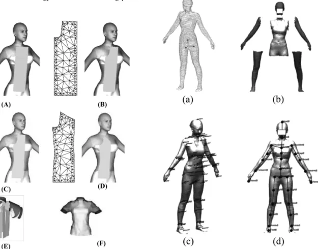
4.2. Interactive pattern design using real-time pat- tern deformation
Figure 5 shows an example for the front bodice pattern drawing using the proposed interactive method. Starting from an initial rectangular cloth (Figure 5a), the boundary vertices of the 2D flat pattern mesh was adjusted by user (Figure 5b) with simultaneously updated 3D drape results.
After repeating the procedures, a final pattern was acquired as in Figure 5d. Figure 5e and 5f shows the patterns with sewing information and a simulation result. The interactive method can be used not only in the initial drawing of pat- terns, but also in the editing of 3D simulation result. Figure 6 shows the dynamically edited result of a skirt from Fig- ure 4j. The same methodology can be used to cutting pat-
terns or adjusting lengths of patterns such as trousers. The advantage is that the designer can modify the patterns watching the 3D drape result.
4.2. Relative human body coordinates system
To apply a relative human body coordinate system to the designed patterns, body feature points should be detected first. Heuristic rules were acquired from scan data database
Fig 5. Example of an interactive pattern design (a) initial cloth (left: 2D pattern, (b) right : 3D drape result (e) initial 3D posi- tioning of patterns (f) simulation result
Fig. 6. A partially modified skirt from Figure 1
Fig. 7. Automatic detection of anthropometric feature points and bone structure
(a) raw point slices (b) dissected six body parts
(c) feature points (d) bone structure
of various body shapes and they were simplified to a deci- sion tree as shown in Figure 2. The reason we used multi- ple measurement methods based on decision tree is that a single rule cannot recognize all the various body shapes.
For example, a waist point is defined as a concave point from a front view, but a fat body may not have such a con- cave point. So rules for a standard body shape and a singu- lar body shape should be discriminated. Figure 7 is the result of our heuristic research and it showed a good corre- lation with manual assessment for the SizeKorea scan data.
To show the validity of the feature point detection algo- rithm, the raw 3D scan data were converted to slices of point clouds (Figure 7a) and they were classified into six groups of body parts (Figure 7b). The feature points and the bone structure were detected automatically from the 3D body scan data as shown in Figure 7c and 7d. The 3D scan data generally has a T-shaped stance and each body part has a cylinder-like shape. Thus we can assign a local cylindri- cal coordinate system to each body part of Figure 7b. The position of each pattern of Figure 5e was described by the nearest body part and its local cylindrical coordinates.
The advantage of using relative human body coordinate system can be illustrated by Figure 8. A garment pattern set designed for a specific body size (Figure 8a) cannot be used without re-positioning if the new body has different sizes (Figure 8b). But if the patterns were described by our rela- tive human body coordinates, their position can be adjusted to a new body (Figure 8c). Finally after a few additional drape simulation loops, the garment can be put on by the new body (Figure 8d). Using this scheme, any garment set can be reused to any size of body without manual modifica- tion. Simply speaking, we can use same coordinate system for different body parts. For example, relative coordinate (radius, theta, z)=(0, 0, 0) means right hand tip in the case of Figure 3, while it could mean left foot tip in the case of the left leg (refer to Table II). This feature is important in
an internet based garment market where each individual customer wants a garment to fit his/her body. Once the cus- tomer’s feature points are known, the garment patterns can be automatically positioned in the right place and direction if only relative human body coordinate system is prelimi- narily prepared in the garment pattern data.
5. Conclusions
An interactive garment pattern design method was imple- mented using real-time pattern deformation algorithm. The designer can draw or edit 2D patterns watching the 3D drape simulation change simultaneously. The proposed method is similar to the flat pattern method in that a 2D pattern is manipulated and also similar to the pattern drap- ing method in that the 3D drape result on a human body is used in the design. Thus it has the hybrid method of the two traditional methods and contains the advantages of both. The positions of generated patterns were described by the relative coordinates with respect to body parts, so a gar- ment set can be re-used to any new body without a manual re-positioning process. The relative human body coordinate system approach will be useful especially in the internet based garment trade where the customers have various body shapes and sizes.
References
Azouz, Z. B., Shu, C., & Mantel, A. (2006). Automatic Locating of Anthropometric Landmarks on 3D Human Models. Pro- ceedings of the Third International Symposium on 3D Data Processing, Visualization, and Transmission (3DPVT'06), USA, 750-757.
Baraff, D., & Witkin, A. (1998). Large steps in cloth simulation.
ACM Transactions on Graphics, 17(1), 43-54.
Dekker, L., Douros, I., Buxton, B., & Treleaven, P. (1999). Build- Fig. 8. Example of pattern realignment using relative coordinates.
ing symbolic information for 3D human body modeling from range data. Proceedings of the Second International Confer- ence on 3-D Digital Imaging and Modeling (3DIM’99), Can- ada, 388-397.
Etzmuss, O., Keckeisen, M., & Strasser, W. (2003). A fast finite element solution for cloth modeling. Proceedings of Com- puter Graphics, 244-251.
Han, H. S., (2006). A Study on the Automatic Setting of 3D Body Landmarks and Measuring Paths for Apparel, Ph.D. thesis, Seoul National University
Klosowski, J. T., Held, M., Mitchell, J. S. B., Sowizral, H., &
Zikan, K. (1998). Efficient collision detection using bound- ing volume hierarchies of k-DOPs. IEEE Transactions on Visualization and Computer Graphics, 4(1), 21-36.
Maya nCloth,. (2010). Autodesk. Retrieved July 26, 2010, from http://usa.autodesk.com
Nurre, J. (1997). Locating Landmarks on Human Body Scan Data. Proceedings of the International Conference on Recent Advances in 3-D Digital Imaging and Modeling (3DIM’97), Canada, 285-295.
Marvelous. (2009). Clo Virtual Fashion. Retrieved July 26, 2010, from http://www.clo.co.kr/
Oh, S., Ahn, J., & Wohn, K. (2006). Low damped cloth simula- tion. The Visual Computer, 22(2), 70-79.
Pandurangan, P., Eischen, J., Kenkare, N., & Lamar, T. A. M.
(2008). Enhancing accuracy of drape simulation. Part II:
Optimized drape simulation using industry-specific software.
Journal of the Textile Institute, 99(3), 219-226.
Park, C.K., Sul, I.H., Park, Y., & Kim, S. (2007). Vision and Implmentation of i-Fashion. The 23rd IAF World Apparel Convention, Teipei, Taiwan, 1-4.
Qualoth. (2004). FxGear. Retrieved July 26, 2010, from http://
qualoth.com/
Shewchuk, J. (2002). Delaunay Refinement Algorithms for Tri- angular Mesh Generation. Computational Geometry: The- ory and Applications, 22(1-3), 21-74.
Sul, I. H., Kim, S. M., Chi Y., & Kang, T. J. (2006). Simulation of Cusick Drapemeter Using Particle Based Modeling : Sta- bility Analysis of Explicit Integration Methods. Textile Research Journal, 76(9),712-719.
Sul, I. H., (2010). Fast Cloth Collision Detection Using Collision Matrix, International Journal of Clothing Science and Tech- nology, 22(2),145-160.
Sul, I. H., & Kang, T. J. (2010). Regeneration of 3D body scan data using semi-implicit particle based method. International Journal of Clothing Science and Technology, 22(4), 248-271.
Sze, K. Y., & Liu, X. H. (2007). Fabric drape simulation by solid-shell finite element method. Finite Elements in Analy- sis and Design, 43(11-12), 819-838.
v-Stitcher. (2000). Browzwear. Retrived July 26, 2010, from http://www.browzwear.com/
Yu, W. R., Kang, T. J., & Chung, K. (2000). Drape Simulation of Woven Fabrics by Using Explicit Dynamic Analysis. Jour- nal of Textile Institute, 91(2), 285-301.
(2010년 5월 26일 접수2010년 8월 27일 1차 수정/2010년 8월 27일 게재확정)