A Numerical Study on Heat Transfer and Friction in Rectangular Channel with Inclined Perforated Baffles
Ary Bachtiar Krishna Putra*․Soo-Whan Ahn†and Ho-Keun Kang**
(Received February 15, 2008 ; Revised March 21, 2008 ; Accepted May 29, 2008)
Abstract:A three dimensional numerical study has been applied to predict the turbulent fluid flow and heat transfer characteristics for the rectangular channel with different types of baffles. Four different types of the baffles are used. The inclined baffles have the width of 19.8 cm, the square diamond type hole having one side length of 2.55 cm, and the inclination angle of 5o. Reynolds number is varied between 23,000 and 57,000. The SST k -ω turbulence model is used in the present numerical study. The validity of the numerical results is examined with the experimental data. The numerical results of the flow field depict that the flow patterns around the different baffle type are entirely different and it significantly affects the local heat transfer characteristics. The heat transfer and friction factor depend significantly on the number of baffle holes. It is found that the heat transfer enhancement of baffle type II (3 hole baffle) has the best values.
Key words:Friction factor, Heat transfer, Perforated inclined baffle, Rectangular channel, Square diamond type hole
†Corresponding Author(School of Mech. & Aerospace Eng., Institute of Marine Industry, Gyeongsang National University, E-mail:[email protected], Tel: 055)640-3125)
* Graduate School, Gyeongsang National University(on leave from Sepuluh Nopember Institute Technology, Indonesia)
** Korean Register of Shipping
Nomenclature
A : heat transfer area, m2 Cp : specific heat of air, J/kg °C
Dh : hydraulic diameter of the channel, m f : friction factor,
: production of
h : heat transfer coefficient, W/m2 °C H : test section height, m
K : thermal conductivity of air, W/m °C Lo : test section length, m
: mass flow rate, kg/s
Nu : Nusselt number, hDh/k
: production of Pr : Prandtl number
: heat transfer rate, W Re : Reynolds number T : temperature, °C u : air velocity, m/s W : test section width, m
x : distance from entrance of the heated test section, m
: dissipation of
Greek symbols
: turbulent kinetic energy, m2/s2
: air density, kg/m3
: specific dissipation rate, N/m2 s
: viscosity, kg/m s
: turbulent viscosity, kg/m s
: turbulent Prandtl number
Subscripts
1 : entrance 2 : exit
avr : average value of channel b : bulk
ra : average value of channel for 4 walls ss : empirical correlation for smooth
channel w : wall
1. Introduction
Like ribs, jet impingement and other
passive heat transfer enhancement
methods, insertion of baffle in a cooling systems has been used for various types of industrial applications such as internal cooling systems of gas turbine blades, electronic cooling devices, shell-and-tube type heat exchangers, thermal regenerators, and labyrinth seals for turbo-machines.
Among important studies, Tsay et al[1]. numerically investigated the heat transfer enhancement on a vertical baffle in backward facing step flow channel. The effect of the baffle height, thickness and the distance between the baffle and the backward facing step on the flow was studied. They found that an insertion of a baffle into the flow could increase the
average Nusselt number by 190%. They also observed that the flow conditions and heat transfer characteristics are strong function of the baffle position. Berner et al[2]. obtained experimental result of mean velocity and turbulent distribution in flow around segmented baffles. Experimental investigation of the turbulent flow and heat transfer characteristics inside the periodic cell formed between segmented baffles staggered in a rectangular duct was studied by Habib et al[3]. Numerical predictions of the flow and heat transfer in channel with staggered fins were investigated by Webb and Ramadhyani[4], Kelkar and Patankar[5], and Habib et al[6].
All of the previous investigations used the solid segmented baffles. Experimental study of Dutta and Dutta[7] on perforated baffles showed better heat transfer augmentation with perforations compared to that with a solid baffles, if the plate is attached to the heated surface and properly aligned in the direction of the flow.
There are very few numbers of research works conducted numerically to capture more detail of the fluid flow pattern and heat transfer phenomena in the channel with the perforated baffle. Yang and Hwang[8] reported the numerical prediction of the turbulent fluid flow and heat transfer characteristics for the rectangular channel with the porous baffle which were vertically arranged on the bottom and top channel walls. In this research the turbulent governing equations are solved by a control volume-based finite difference method with k -ε turbulent model associated with wall function. The numerical results indicate that the flow patterns around the porous- and solid -type
were entirely different due to different transport phenomena, and it significantly influences the local heat transfer distributions. The lack of research in numerical analysis for perforated baffles motivates the present study to analyse numerically the turbulent flow structure and associated heat transfer enhancement in the rectangular channel with inclined solid-and perforated-type baffles. An experimental work is also performed to validate the numerical result. This work employs inclined baffles with different perforation density, having the baffle width of 19.8 cm and the square diamond type holes having one side length of 2.55 cm.
These baffles have the number of holes of up to 9 and the inclination angle of 5o. Turbulent convective heat transfer is analyzed using the Reynolds Average Navier-Stokes (RANS) with SST k -ω turbulence model.
2. Experimental setup
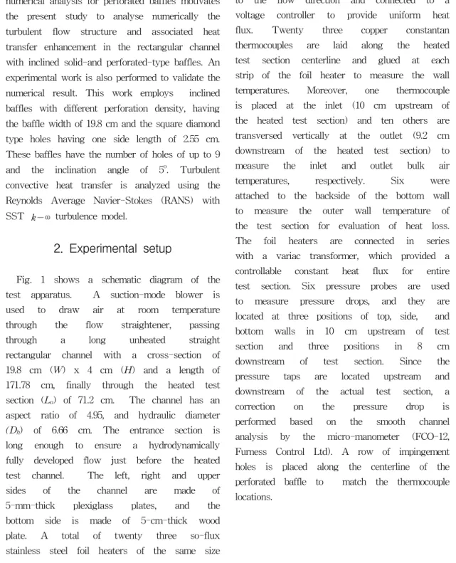
Fig. 1 shows a schematic diagram of the test apparatus. A suction-mode blower is used to draw air at room temperature through the flow straightener, passing
through a long unheated straight
rectangular channel with a cross-section of 19.8 cm (W) x 4 cm (H) and a length of 171.78 cm, finally through the heated test section (Lo) of 71.2 cm. The channel has an aspect ratio of 4.95, and hydraulic diameter (Dh) of 6.66 cm. The entrance section is long enough to ensure a hydrodynamically fully developed flow just before the heated test channel. The left, right and upper sides of the channel are made of 5-mm-thick plexiglass plates, and the bottom side is made of 5-cm-thick wood plate. A total of twenty three so-flux stainless steel foil heaters of the same size
of 198 mm x 30 mm x 0.1 mm are mounted on the bottom surface of the test section.
These foil heaters are aligned perpendicular to the flow direction and connected to a voltage controller to provide uniform heat flux. Twenty three copper constantan thermocouples are laid along the heated test section centerline and glued at each strip of the foil heater to measure the wall temperatures. Moreover, one thermocouple is placed at the inlet (10 cm upstream of the heated test section) and ten others are transversed vertically at the outlet (9.2 cm downstream of the heated test section) to measure the inlet and outlet bulk air temperatures, respectively. Six were attached to the backside of the bottom wall to measure the outer wall temperature of the test section for evaluation of heat loss.
The foil heaters are connected in series with a variac transformer, which provided a controllable constant heat flux for entire test section. Six pressure probes are used to measure pressure drops, and they are located at three positions of top, side, and bottom walls in 10 cm upstream of test section and three positions in 8 cm downstream of test section. Since the pressure taps are located upstream and downstream of the actual test section, a correction on the pressure drop is performed based on the smooth channel analysis by the micro-manometer (FCO-12, Furness Control Ltd). A row of impingement holes is placed along the centerline of the perforated baffle to match the thermocouple locations.
Pressure drop measuring device
Pressure drop measuring device
Power supply &
thermocouple readout
Foil heater with thermocouple Baffle Fully developed flow
To suction blower Plexiglass
Wood
Fig. 1 Schematics of test apparatus
Sw Sw
2xSl
Sw SlSl
L
W W
L L
W W
L
Hw
Hw
Hw
Type I Type II Type III Type IV Fig. 2 Baffle plate configuration
All baffle types mounted on the heated wall have a constant inclination angle of five degrees and a gap of 4 mm between heated surface and the baffle is maintained to avoid flow stagnation. The baffle is placed at the position of 9.5 cm downstream from the start of the heated test section.
Leading edge of the baffle is kept sharp to reduce possible flow disturbance by the protruding edge. In this study, all baffle types have the same overall size of length of 23.2 cm, width of 19.8 cm, and thickness of 5 mm, but different number of holes.
Four different types such as the solid baffle (baffle type I), the 3 hole baffle (baffle type II), the 6 hole baffle (baffle type III), and the 9 hole baffle (baffle type IV) were dealt with, respectively. These square diamond type holes of width, Hw = 2.55 cm, transverse gap, Sw = 1.2 cm, and longitudinal gap, Sl = 7.6 cm were manufactured as shown in Fig. 2. All of the thermocouples used in the experiment are carefully calibrated to an accuracy of 0.5 oC.
The mass flow rate within the channel is
varied by changing the flow area of the
suction blower. The experimental
uncertainties are estimated using the
procedure outlined by Kline and
McClintock[9]. The variables measured in this experiment are wall temperature, air temperature, velocity and pressure drop. It is found that the uncertainties for Reynolds number, friction factor and Nusselt number are about 2.5%, 9.5%, and 7.8%, respectively.
3. Numerical modelling
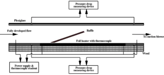
The numerical simulations are performed in three dimensional domain, which represents a rectangular channel with the inclined perforated-type baffle, as shown in Fig. 3. The software (ICEM CFD 10) is used to draw all parts in computational domain and to generate grid. The dimensions of computational domain are idealized to reveal the fundamental issues and enable validation with available experimental data. This computational domain has the same size with the experimental model (LO = 71.2 cm, W = 19.8 cm, and H = 4 cm). Unstructured tetrahedral grids, with prism smoothing near bottom wall, near top wall and near baffle surface are used to resolve high velocity gradient. The total number of nodes in those domains are more than 500,000 and total number of tetrahedrons are more than 1,500,000.
In the present numerical model, a uniform heat flux is specified on the bottom wall (heated wall). All walls in the rectangular channel except bottom wall are defined as an adiabatic wall.
Fig. 3 Grid system arrangements around the baffle plate
The zonal modelling uses Wilcox's k -ω model near solid walls and Launder and Sharma's model near boundary layer edges and in free shear layers. This switching is achieved with a blending function F1 of the model coefficients as follows:
SST model = F1⋅( k - ω model)
+ (1-F1)⋅(k-εmodel) (1)
where the standard k -ω was first proposed by Wilcox[10] as follows:
(2)
(3)
And k - ε model was used by Launder and Sharma's model[11]. The SST model requires the distance of a node to the nearest wall for performing the blending between and k -ω. The wall scale equation is the equation solved to get the wall distance, simply:
∇ (4)
where φ is the value of the wall scale. the wall distance can be calculated from the wall scale through:
wall distance = ( | ∇φ|2+2φ) -| ∇φ| (5)
4. Data reduction
The local heat transfer coefficient is calculated from the net heat transfer rate per unit surface area exposed to the cooling air, the local wall temperature (Tw), and the local bulk mean air temperature (Tb) as follows :
(6)
where A is the total heat transfer area of the heated wall. The heat transfer rate () is defined as:
(7)
where Tb1 and Tb2 represent the fluid bulk temperatures at the entrance and exit, respectively. The local Nusselt number is defined using the local heat transfer coefficient and the hydraulic diameter Dh
for the rectangular channel:
(8)
The local Nusselt number is normalized by the Nusselt number for fully developed turbulent flow in a smooth circular tube correlated by McAdams/Dittus-Boelter[12]
as:
(9)
The Reynolds number was calculated on the basis of bulk average velocity and hydraulic diameter. The channel average velocity in the test section was obtained from the flow rate of the circular tube at downstream of test section.
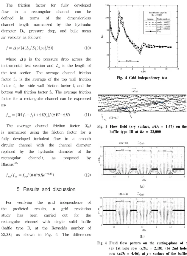
The friction factor for fully developed flow in a rectangular channel can be defined in terms of the dimensionless channel length normalized by the hydraulic diameter Dh, pressure drop, and bulk mean air velocity as follows:
(10)
where p is the pressure drop across the instrumental test section and is the length of the test section. The average channel friction factor fra is the average of the top wall friction factor ft, the side wall friction factor fs and the bottom wall friction factor fb. The average friction factor for a rectangular channel can be expressed as:
(11)
The average channel friction factor (fra) is normalized using the friction factor for a fully developed turbulent flow in a smooth circular channel with the channel diameter replaced by the hydraulic diameter of the rectangular channel), as proposed by Blasius12):
(12)
5. Results and discussion
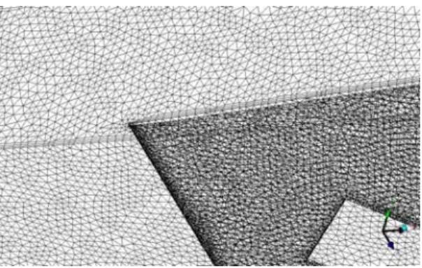
For verifying the grid independence of the predicted results, a grid resolution study has been carried out for the rectangular channel with single solid baffle (baffle type I), at the Reynolds number of 23,000, as shown in Fig. 4. The differences
x/Dh
0 2 4 6 8 10 12
0 50 100 150 200 250
node : 568755 node : 506722 node : 463944 node : 329688 Exp.
Nu
Legend Node numbers Re = 23000 Solid baffle (type I)
Baffle
Fig. 4 Grid independency test
Fig. 5 Flow field (x-y surface, z/Dh = 1.47) on the baffle type III at Re = 23,000
(a)
(b)
Fig. 6 Fluid flow pattern on the cutting-plane of : (a) 1st hole row (x/Dh = 2.18), (b) 2nd hole row (x/Dh = 4.46), at y-z surface of the baffle type III at Re = 23,000
were found to be minor in the range of the node number of 329,688 to 568,755. The node number of 568,755 has been used in the solid baffle(baffle type I). The present experimental data don't precisely match the numerical results.
It is not surprising because the discrepancies between calculated and measured results may be attributed to variable fluid property and the possible influence of buoyancy in the experimental system. In addition, as mentioned earlier, one thermocouple in each heater gives the local wall temperature at channel centerline (location of jet impingement) and therefore, presented results do not reflect span- averaged Nusselt number characteristics.
(a)
(b)
Fig. 7 Isotherms on the cutting-plane of : (a) 1st hole row (x/Dh = 2.18), (b) 2nd hole row (x/Dh = 4.46), at y-z surface of the baffle type III at Re = 23,000
x/D h
0 2 4 6 8 10 12
0 50 100 150 200 250 300
num.
exp.
Nu
Re = 23000
Baffle
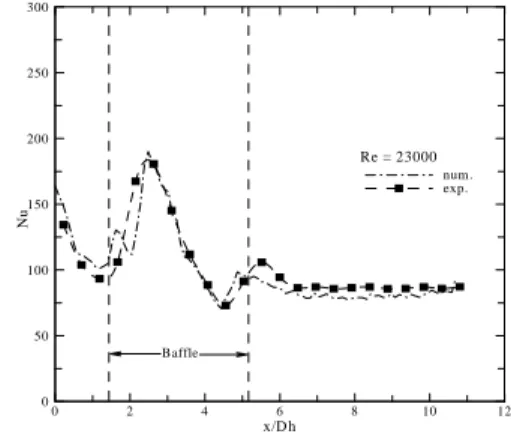
Fig. 8 Centerline local Nusselt number for baffle type III at Re = 23,000
+ +
+ +
Reynolds number, Re
100000 20000 30000 40000 50000 60000
0.005 0.01 0.015 0.02 0.025 0.03
I II III IV Smooth channel Blasius +
frictionfactor,fra
Num. Exp. Baffle type
Fig. 9 Friction factor for different baffle types
The local Nusselt number is
comparatively higher at the start of heating section due to the steeper development of the thermal boundary layer. The local Nu peaks are experienced at the dimensionless axial location of x/Dh = 2.2 because the gap between the baffle leading edge and the heating wall (bottom wall) generates the flow acceleration and flow impingement.
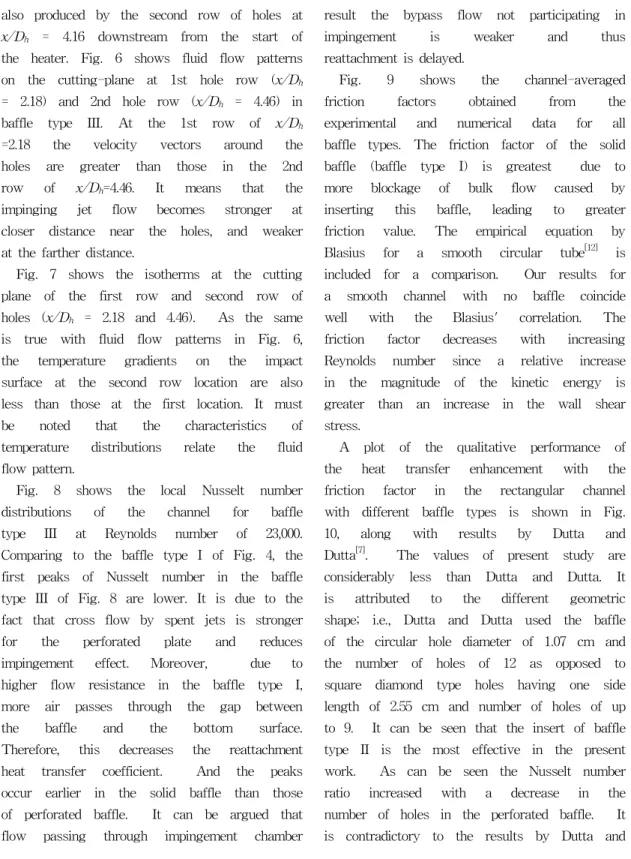
Fig. 5 shows the flow field of two impinging jets on x-y surface in the baffle type III; i. e., first impingement is produced by the three holes at the first row of holes at the dimensionless axial location
of x/Dh = 2.18. And second impingement is also produced by the second row of holes at x/Dh = 4.16 downstream from the start of the heater. Fig. 6 shows fluid flow patterns on the cutting-plane at 1st hole row (x/Dh
= 2.18) and 2nd hole row (x/Dh = 4.46) in baffle type III. At the 1st row of x/Dh
=2.18 the velocity vectors around the holes are greater than those in the 2nd row of x/Dh=4.46. It means that the impinging jet flow becomes stronger at closer distance near the holes, and weaker at the farther distance.
Fig. 7 shows the isotherms at the cutting plane of the first row and second row of holes (x/Dh = 2.18 and 4.46). As the same is true with fluid flow patterns in Fig. 6, the temperature gradients on the impact surface at the second row location are also less than those at the first location. It must be noted that the characteristics of temperature distributions relate the fluid flow pattern.
Fig. 8 shows the local Nusselt number distributions of the channel for baffle type III at Reynolds number of 23,000.
Comparing to the baffle type I of Fig. 4, the first peaks of Nusselt number in the baffle type III of Fig. 8 are lower. It is due to the fact that cross flow by spent jets is stronger for the perforated plate and reduces impingement effect. Moreover, due to higher flow resistance in the baffle type I, more air passes through the gap between the baffle and the bottom surface.
Therefore, this decreases the reattachment heat transfer coefficient. And the peaks occur earlier in the solid baffle than those of perforated baffle. It can be argued that flow passing through impingement chamber
is stronger in perforated baffle and as a result the bypass flow not participating in
impingement is weaker and thus
reattachment is delayed.
Fig. 9 shows the channel-averaged friction factors obtained from the experimental and numerical data for all baffle types. The friction factor of the solid baffle (baffle type I) is greatest due to more blockage of bulk flow caused by inserting this baffle, leading to greater friction value. The empirical equation by Blasius for a smooth circular tube[12] is included for a comparison. Our results for a smooth channel with no baffle coincide well with the Blasius' correlation. The friction factor decreases with increasing Reynolds number since a relative increase in the magnitude of the kinetic energy is greater than an increase in the wall shear stress.
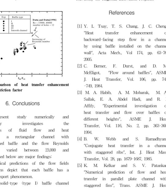
A plot of the qualitative performance of the heat transfer enhancement with the friction factor in the rectangular channel with different baffle types is shown in Fig.
10, along with results by Dutta and Dutta[7]. The values of present study are considerably less than Dutta and Dutta. It is attributed to the different geometric shape; i.e., Dutta and Dutta used the baffle of the circular hole diameter of 1.07 cm and the number of holes of 12 as opposed to square diamond type holes having one side length of 2.55 cm and number of holes of up to 9. It can be seen that the insert of baffle type II is the most effective in the present work. As can be seen the Nusselt number ratio increased with a decrease in the number of holes in the perforated baffle. It is contradictory to the results by Dutta and
Dutta[7], which investigated the Nusselt numbers of smaller scale hole-perforated baffle and concluded that the Nusselt number ratio increased with an increase in the number of holes. The discrepancy between the two can be understood as follows: The quantity of air passing through the baffle holes is essential to an enhancement of Nusselt number in the smaller scale hole-perforated baffle.
However, the impinging jet is imperative in the larger scale hole-perforated baffle.
0 1 2 3 4 5
0 0.5 1 1.5 2 2.5 3 3.5 4
I II III IV Smooth channel
Nu/Nuavrss
fra/fss Exp. Baffle type
D utta and D utta[1998]
Re = 33000, 40000 number of holes = 12
Increasing of Reynolds number Num.
Fig. 10 Comparison of heat transfer enhancement and friction factor
6. Conclusions
The present study numerically and
experimentally investigates the
characteristics of fluid flow and heat transfer in a rectangular channel with single inclined baffle and the flow Reynolds number is varied between 23,000 and 57,000. Listed below are major findings:
1) Numerical predictions of the flow fields and isotherms depict that each baffle has a different transport phenomenon.
2) The solid-type (type I) baffle channel
has the highest friction factor due to more flow blockage.
3) The Nusselt number ratios are greatest at the baffle type II. And the Nusselt number ratio increases with a decrease in number of holes in the perforated baffles.
Acknowledgements
This work was supported by the New University for Regional Innovation Projects.
References
[1] Y. L Tsay, T. S. Chang, J. C. Cheng,
"Heat transfer enhancement of backward-facing step flow in a channel by using baffle installed on the channel wall", Acta Mech., Vol 174, pp. 63-76, 2005.
[2] C. Berner, F. Durst, and D. M.
McEligot, "Flow around baffles", ASME J. Heat Transfer, Vol. 106, pp. 743 -749, 1984.
[3] M. A. Habib, A. M. Mobarak, M. A.
Sallak, E. A. Abdel Hadi, and R. I.
Affify, "Experimental investigation of heat transfer and flow over baffles of different heights", ASME J. Heat Transfer, Vol. 116, No. 2, pp. 363-368, 1994.
[4] B. W. Webb and S. Ramadhyani,
"Conjugate heat transfer in a channel with staggered ribs", Int. J. Heat Mass Transfer, Vol. 28, pp. 1679-1687, 1985.
[5] K. M. Kelkar and S. V. Patankar,
"Numerical prediction of flow and heat transfer in parallel plate channel with staggered fins", Trans. ASME J. Heat
Transfer, Vol. 109, pp. 25-30, 1987.
[6] M. A. Habib, A. E. Attya, and D. M.
McEligot, "Calculation of turbulent flow and heat transfer in channels with streamwise-periodic flow", Trans.
ASME J. Turbomach., Vol. 110, pp.
405-411, 1988.
[7] P. Dutta and S. Dutta, "Effect of baffle size, perforation and orientation on internal heat transfer enhancement", Int. J. Heat Mass Transfer, Vol. 41, No. 19, pp. 3005-3013, 1988.
[8] Y. T. Yang and C. Z. Hwang,
"Calculation of turbulent flow and heat transfer in a porous-baffled channel", Int. J. Heat Mass Transfer, Vol. 46, pp.
771-780, 2003.
[9] S. J. Kline and F. A. McClintock,
"Describing uncertainty in single sample experiments", Mechanical Engineering, Vol. 75, pp. 3-8, 1953.
[10] D. C. Wilcox, Turbulent modelling for CFD. 2nd ed., DCW Industries, 1998.
[11] B. E. Launder and B. I. Sharma,
"Application of the energy-dissipation model of turbulence to the calculation of flow near a spinning disc", Letters in Heat and Mass Transfer, Vol. 1, Issue 2, pp. 131-137, 1974.
[12] W. M. Kays and M. E. Crawford, Convective heat and mass transfer, 2nd ed., McGraw-Hill, New York, 1990.
Author Profile
Ary Bachtiar Krishna Putra
He received his B.S.(1995) and M. S.
degrees(2004) in Sepuluh Nopember Institute of Technology, Indonesia. He is currently an assistant professor who has maintained the leave of absence in Sepuluh Nopember Institute of Technology and Ph. D. candidate in Gyeongsang National University, Korea.
Soo-Whan Ahn
He received his B. S. degree in Fisheries National University of Busan(1976), his M. A. S. degree in University of Ottawa(1990), Canada, and his Ph. D. in Pusan National University(1995). He is currently a professor in Gyeongasng National University.
Ho-Keun Kang
He graduated from Korea Maritime University(B.A. 1992 and M.S. 1997) in Korea. He received his Ph.D degree (2002) from Kobe University in Japan.
He worked at Gyeongsang National University for 6 years as a research professor. He currently works in Research and Development Center, Korean Register of Shipping (KR). His interests are Heat transfer, fluid-induced noise, various energy problems including renewable energy and cruise ship.