A New Direct Torque Control Method of Induction Motor for Torque Ripple Reduction
Deok-Ki Kim*․Jong-Su Kim**․Sung-Hwan Kim**․Hyun-Soo Kim***․Won-Ouk Kim****․
Kyoung-Kuk Yoon***** and Sae-Gin Oh†
(Received August 27, 2008 ; Revised October 14, 2008 ; Accepted November 20, 2008)
Abstract:Direct Torque Control[DTC] and Vector Control are the two schemes developed for high performance induction motor drives. DTC based induction motors are being increasingly used in various industrial applications. DTC offers fast torque response and better speed control with lesser hardware and processing costs as compared to vector controlled drives. However, conventional DTC suffers from high torque ripple, current harmonics and low performance during torque transients. In this paper a new Direct Torque Control[DTC] method of induction motor is presented. In comparison with the conventional DTC method, the PWM technique is applied to proposed control method. In this method, decoupling mechanism is not required and the torque, the flux magnitude are under control using PI controllers and generating the voltage command for inverter control. Therefore torque and speed ripple could be reduced in comparison with the conventional switching table DTC.
Key words:Direct torque control[DTC], Vector control, Induction motor, Torque ripple
†Corresponding Author(Training Center of Ship Operation of Korea Maritime University, E-mail : [email protected], Tel: 051)410-5094)
* Project Planning Dep't 2 / Shipbuilding Division, Hyundai Heavy Industry Co. Ltd.
** Division of Mechatronics Engineering, Korea Maritime University.
*** Division of Marine Engineering, Mokpo National Maritime University.
**** Training Center of Ship Operation of Korea Maritime University.
***** Health Stream Korea Rep. Department Manager.
1. Introduction
Recently, induction motor control system using vector control theory[1], [2] is applied extensively in developing high efficiency industry application field. This control system uses position and speed sensors such as pulse generator or encoder and receives the position and the speed signal to detect the rotor speed or
the flux angle of induction motor using
complicated arithmetic and many
controllers. Therefore electric motor drive system that apply vector control algorithm need complicated mathematical calculation and much expenses are spent in system embodiment.
But Direct Torque Control[DTC]
controls torque and flux of induction motor in the manner of closed loop system
without using current loops in comparison with the conventional vector controlled systems. In principle, the DTC system requires the knowledge of stator resistance only and decreasing the sensitivity to parameter variations.
Moreover the DTC systems don't require satisfying a coordinate transformation between stationary and synchronous frame in comparison with the conventional vector controlled systems. In the DTC, motor torque and flux are controlled by the stator voltage space vector using optimum inverter switching table. The use of a switching table for voltage vector selection provides fast torque response and low inverter switching frequency without the complex field orientation by restricting the flux and torque errors within respective flux and torque hysteresis bands with the optimum selection being made.
However DTC suffer from certain disadvantages like high ripple torque, poor performance during starting and low speed operation, problems during changes
in torque command and changing
switching frequency.
In this paper presents a new induction motor speed control method using well developed PWM technique applied to inverter control in the conventional DTC for reducing torque and speed ripple and through computer simulation, confirm effectiveness of proposed method.
2. Conventional DTC
The electromagnetic torque developed by an induction motor can be expressed in
a number of ways, one of which is
(1)
where is the angle between the stator flux vector and rotor flux vector , often known as torque angle. This equation indicates that can be directly controlled by .
The main variable to be controlled in the DTC scheme is the stator flux vector
and relates the stator voltage vector by
(2)
The equation shows that the derivative of reacts instantly to changes in . The stator voltage , which is the inverter output voltage, can be controlled by the reference vector in the space vector modulation. Since is synthesized by the stationary voltage vectors of the inverter, a proper selection of the stationary vectors can make the magnitude and angle of adjustable.
Fig. 1 shows the principle of DTC for a two level VSI fed induction motor drive.
The -axis plane for stator flux is divided into six sectors Ⅰ to Ⅵ. The stator flux in the figure falls into sector Ⅰ, and its angle is referenced to the -axis of the stationary reference frame. The rotor flux vector lags by .
Fig. 1 Principle of direct torque control
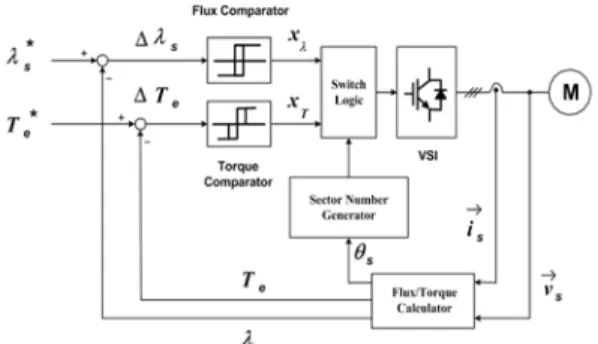
Fig. 2 shows a typical block diagram of a DTC induction motor drive. Both flux and Torque comparators are of a hysteresis(tolerance band) type. The flux comparator has two output levels(=+1,-1) while the torque comparator has three output levels(
=+1,0,-1), where '+1' requests an increase in or
, '-1' demands a decrease in or , and '0' signifies no changes.
Fig. 2 Block diagram of direct torque control scheme
Table 1 gives the switching logic for the stator flux reference λ*s rotating in the counterclockwise direction. The input variables are
, , and the sector number, and the output variables are the inverter voltage vectors.
Table 1 Switching Logic for Rotating in the Counterclockwise Direction
Comparator
Output Sector
Ⅰ Ⅱ Ⅲ Ⅳ Ⅴ Ⅵ
+1 +1 +1 0 +1 -1 -1 +1
-1 0 -1 -1
The stator flux vector λ
s in the stationary frame can be expressed as
λs=λds+jλqs
= ⌠⌡ (vds-Rsids)dt +j⌠⌡ (vqs-Rsiqs)dt (3)
from which its magnitude and angle are
(4)
(5)
where , , and are the measured stator voltages and currents. The developed electromagnetic torque can be calculated by
(6)
The above equations illustrate that the stator flux and developed torque can be obtained by using measured stator voltages and currents. The only motor parameter required in the calculations is the stator resistance . This is in contrast to the direct rotor flux FOC schemes, where almost all the motor parameters are needed.
3. Proposed DTC method
The principle of vector control of induction motor is to align the flux and torque current along the -axis and -axis of the reference frame, respectively. So the torque could be controlled by the associated current component, once the flux is kept constant. In contrast, the fundamental technique of DTC is to control both the torque and the magnitude of flux within the associated error bands in real time. These control could be achieved by selecting the inverter switching states according to the errors of torque and flux.
Therefore the main advantage of DTC is to regulate the torque and magnitude of flux directly without need any concept of field orientation.
Fig. 3 Block diagram of the proposed DTC method
Fig 3 shows the block diagram of the proposed induction motor control drive. As shown in figure two PI controllers regulate the flux amplitude and torque, respectively. Therefore both the torque and the magnitude of flux are under control, thereby generating the voltage command for inverter control. In this method decoupling mechanism is not required since the flux magnitude and torque could be regulated by the PI controllers. The Proposed method uses
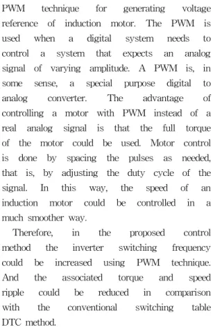
PWM technique for generating voltage reference of induction motor. The PWM is used when a digital system needs to control a system that expects an analog signal of varying amplitude. A PWM is, in some sense, a special purpose digital to analog converter. The advantage of controlling a motor with PWM instead of a real analog signal is that the full torque of the motor could be used. Motor control is done by spacing the pulses as needed, that is, by adjusting the duty cycle of the signal. In this way, the speed of an induction motor could be controlled in a much smoother way.
Therefore, in the proposed control method the inverter switching frequency could be increased using PWM technique.
And the associated torque and speed ripple could be reduced in comparison with the conventional switching table DTC method.
4. Computer simulation results
The system was simulated using PSIM software for proving effectiveness of proposed control method.
Induction motor specification and parameters that used in simulation are same with table 2.
Fig. 4 shows the simulation speed responses for the conventional DTC method. The error bands of torque and flux are 2[%] of rated torque and nominal flux value, respectively.
Table 2 Parameters of induction motor used for computer simulation
Phase/Pole 3 / 6 Stator Resistance(Rs) 0.294 [Ω]
Rotor Resistance(Rr) 0.156 [Ω]
Rotor Leakage
Inductance(Llr) 0.00074[H]
Stator Leakage
Inductance(Lls) 0.00139[H]
Magnetizing Inductance(Lm) 0.041[H]
Moment of Inertia(J) 0.002 [kg-㎡]
PI Gain(Speed, Flux, Torque)
0.01, 0.1/5, 0.001/0.5, 0.01
(a)
(b)
Fig. 4 Speed response in the case of speed command 800 [rpm] based on Conventional DTC (a) rpm, (b) Torque
Fig. 5 shows the simulation speed responses for the proposed DTC method.
As shown in Fig. 5(a) and (b), the speed and torque ripple is reduced as compared with those shown in Fig. 4(a) and (b) for the conventional DTC method. Similar results could be derived for other speed range.
(a)
(b)
Fig. 5 Speed response in the case of speed command 800 [rpm] based on proposed DTC (a) rpm, (b) Torque
Fig. 6 Speed response for step change of speed setting (1200[rpm] → -1200[rpm])
Fig. 6 shows speed response for speed setting step changing. As shown in Figure, could know that motor speed control is carried out well smoothly by proposed control method.
Fig. 7 shows speed response for load torque step changing. A step load, 1[N․
m] which is nearly 50[%] of rated torque,
is applied at 0.6[s]. Similar load characteristics could be derived for other load conditions.
(a)
(b)
Fig. 7 Speed response for step change of load torque.(0 → 1[N․m]) (a) rpm, (b) Torque
5. Conclusion
The vector control method requires complex computation and additionally it is sensitive to changes of motor parameters.
While DTC can control motor by very easy way and decreasing the sensitivity to
parameter variations. However,
conventional DTC suffers from high torque ripple, current harmonics and low performance during torque transients.
In this paper, a new DTC control method is presented to supplement traditional DTC and proved excellency through computer simulation. The main
features of this method can be
summarized as:
1) Algorithm uses torque and flux value without the coordinate transformation.
Therefore the control is become easy.
2) Reducing the speed and torque ripple compare with traditional DTC method.
3) Good dynamic transient characteristics are obtained.
The authors are going to execute an actual experiment and prove effectiveness of method that proposed in this paper in the near future.
References
[1] Peter Vas, "Vector Control of AC Machines." from Clarendon press.
Oxford, 1990.
[2] Y. S. Lai, "Modeling and vector control of induction machines - A new unified approach." in Proc. of the IEEE Power Engineering Society Winter Meeting, 1999, pp.47-52.
[3] T.G. Habetler, F. Profumo, M. Pastorelli, and L. M. Tolbert, "Direct torque control of induction machines using space vector modulation.", IEEE Trans.
Ind, Appl., Vol. 28, no.5, pp.1045-1053, 1992.
[4] P. Tiitinen, "The next generation motor control method, DTC direct torque control." in proceedings of the IEEE Intl. Conf. on Power Electronics, Drives, and Energy Systems for industrial Growth, 1996, pp.37-43.
[5] S. R Bowes, "New sinusoidal pulse width modulated inverter." Proc. IEEE, Vol. 122, no.11, pp.1279-1285, 1975.
Author Profile
Deok-Ki Kim
He received the B.S. and M.S. degrees at the Korea Maritime University, Busan, Korea. He is currently working toward the Ph.D. degree. His interesting parts are in the area of motor speed control and inverter. He is now engaged in Hyundai Heavy Industry Co.
Ltd.
Jong-Su Kim
He received the M.S. and Ph.D degrees at the Korea Maritime University, Busan, Korea. He is currently a professor at the Division of Mechatronics Engineering of Korea Maritime University.
Sung-Hwan Kim
He received the B.S degree from Korea Maritime University, the M.S degree from Bukyung National University and the Ph.D. degree from Busan National University. He is currently a professor at the Division of Mechatronics Engineering of KMU.
Hyun-Soo Kim
He received the B.S degree from Korea Maritime University, the M.S degree from Mokpo National Maritime University and the Ph.D. degree from Korea Maritime University. He is currently a professor at the Division of Marine Engineering, Mokpo National Maritime University.
Won-Ouk Kim
He received the M.S. degrees at the Korea Maritime University, Busan, Korea. His interesting parts are in the area of ship simulation and safety engineering. He is currently working toward the Ph.D. degree.
Kyoung-Kuk Yoon
He received the B.S degree from Korea Maritime University, Busan, Korea. His interesting parts are in the area of electric machinery and control.
He is currently working toward the Ph.D. degree.
Sae-Gin Oh
He received the M.S. and Ph.D.
degrees from Korea Maritime University, Busan, Korea. His interesting parts are in the area of electric machinery and control. He is currently a professor at the Training Center of Ship Operation of KMU.
![Fig. 5 Speed response in the case of speed command 800 [rpm] based on proposed DTC (a) rpm, (b) Torque](https://thumb-ap.123doks.com/thumbv2/123dokinfo/4843464.283440/5.772.408.715.123.485/fig-speed-response-speed-command-based-proposed-torque.webp)
![Fig. 7 Speed response for step change of load torque.(0 → 1[N․m]) (a) rpm, (b) Torque](https://thumb-ap.123doks.com/thumbv2/123dokinfo/4843464.283440/6.772.84.706.99.983/fig-speed-response-step-change-load-torque-torque.webp)
