서론
Roberts1는 임상적으로 성공한 임플란트는 50%이하의 골접 촉이 있다고 하였다. Block 등2도 개에 식립한 임플란트에서도 유사한 수준의 골접촉을 관찰하였다. 최근에 연구한 Coelho 등3 은 인체에서 8년에서 13년간 기능한 임플란트를 인간사체연 구(retrieval study)하였는데 골-임플란트 접촉율이 20 - 80%였다고 보고하였다.
위의 여러 문헌에서도 알 수 있듯이 실제적으로 골-임플란 트 접촉이 100%에 도달할 수 없다. 그러나, 복잡한 골구조, 비용 및 소요 시간의 문제로 거의 대부분의 유한요소문헌은 골과 임플란트의 골접촉을 100%로 가정하여 왔다. 부분적인 골접 촉에 대해 유한요소법을 이용하여 응력/변형을 해석하는 소수 의 연구들이 있는데 최초로 Papavasiliou 등4은 네 가지(100, 75, 50, 25%)의 골-임플란트 접촉비율에 대해 삼차원 유한요소법을 이 용하여 연구하였는데 다른 골접촉율이 응력분산에 영향을 미 치지 않는다고 하였다. 이 연구의 한계점은 요소크기가 1,000 um이상으로 convergence test를 시행한 문헌들5,6이 추천하는 요소 크기인 700 - 750 um보다 커서 오차가 커질 것으로 예상된다.
Lian 등7은 이차원 유한요소법을 이용하여 새롭게 제한한 remodeling algorithm을 이용하여 4 가지(25, 50, 75, 100%)의 골-임 플란트 접촉율을 비교연구하였는데 초기의 골접촉율이 무엇 이든 간에(25 - 100%) 골개형(bone remodelling)이 평형상태에 이르 면 58 - 60%의 골접촉율을 보인다고 언급하였다. Deng 등8은 중 심극한정리(central limit theorem)를 이용하여 임플란트에 골을 무 작위 접촉이 되도록 삼차원 유한요소모형을 제작하였고, 골- 임플란트 접촉율(25, 50, 75%)이 증가할수록 RFA값이 선형적 으로 증가하였다고 보고하였다(P<.001). 그런데 이 연구에서는 피질골을 배제한 골모형을 제작하였다.
여러 조직학적 연구 문헌들3,9-11을 비추어 볼 때 골이 임플란트 에 부착하는 양상은 무작위적으로 접촉함을 추론할 수 있다.
지금까지는 유한요소법을 이용하여 골-임플란트 접촉율에 따 른 응력/변형에 대한 적합한 연구가 매우 부족한 실정이고, 기 존의 연구들에서는 임플란트 전체에 대해서 무작위 골유착을 시켰고 피질골과 해면골을 분리하여 무작위 골유착을 시킨 문 헌은 아직 없었다. 이런 필요성으로 해서 본 연구에서는 비선 형 삼차원 유한요소법을 이용하여 실제적으로 존재하는 부분 적인 골접촉을 재현하는 방법으로 임플란트 전체에 대해서 무
*교신저자: 허허성성주주
110-749 서울시 종로구 연건동 28 서울대학교 치의학대학원 치과보철학교실 02-2072-2661: e-mail, [email protected] 원고접수일: 2011년 4월 25일 / 원고최종수정일: 2011년 4월 27일 / 원고채택일: 2011년 7월 8일
골-임플란트 접촉 양상에 따른 골 변형 연구: 유한요소법적 연구
유동기
1∙김성균
1∙곽재영
1∙김진흠
2∙허성주
1*
1
서울대학교 치의학대학원 치과보철학교실,
2수원대학교 통계정보학과
연구 목적: 기존 대부분의 유한요소 연구에서는 100%의 골-임플란트 접촉을 가정하여 왔으나 인간사체연구(human retrieval study)에서는 골-임플란트 부착비율이 20 - 80%라 고 보고되었다. 본 연구에서는 비선형 삼차원 유한요소법을 이용하여 실제적인 골-임플란트 접촉을 재현하기 위해 무작위 골접촉 양상을 비교연구하고자 하였다.
연구 재료 및 방법: 컴퓨터단층촬영에서 얻은 영상을 근거로 하여 제작한 골모형에 두 가지 디자인의 임플란트(MK III Bra�nemark�, Inplant�)를 상악제2소구치에 해당하는 위 치에 식립한 모형을 만들었다. 골질은 골형 2로서 Lekholm과 Zarb의 분류를 따랐다. 각 임플란트 디자인마다 두 가지(40%, 70%)의 골-임플란트 접촉비율을 가정하였다. 각 디 자인과 골접촉율마다 5개의 모형을 제작하여 총 40 개의 모형을 만들었다. 이 골-임플란트 접촉을 무작위 섞기방식(random shuffle method)으로 하였고 피질골과 해면골을 다 포함하여 골유착을 시킨 군(wholly randomized osseointegration; W)과 피질골과 해면골을 분리하여 골접촉시키기 위해서 각 0.75 mm마다 무작위 골접촉을 시킨 군(segmentally randomized osseointegration; S)을 비교연구하였다.
결과:골-임플란트 접촉율이나 임플란트 디자인에 상관없이 W군과 S군 간 maximum von Mises strain의 평균에 있어서 유의성 있는 차이가 없었다(P=.939). 골-임플란트 접촉 율이 40%보다 70%가 von Mises strain이 유의하게 낮았다(P=.007). 골-임플란트 접촉율이 40%일 때는 Inplant�과 MK III Bra�nemark�의 변형율 간에는 유의성 있는 차이가 없었 으나(P=.116), 골-임플란트 접촉율이 70%일 때 Inplant�에서는 4886 ± 1034 μm/m, MK III Bra�nemark�에서는 7134 ± 1232 μm/m로서 Inplant�의 von Mises strain이 MK III Bra�nemark 의 것보다 유의하게 낮았다(P<.0001).
결론:골-임플란트 접촉을 가정함에 있어서 무작위 섞기방식(random shuffle method)을 이용하여 임플란트 전체에 대해서나 피질골과 해면골을 분리하여 무작위 골-임플란트 접촉을 시키든 간에 통계적으로 유의한 차이가 없어서 표본의 크기에 상관없이 둘 다 유효한 방법이라 할 수 있었다. (대한치과보철학회지 2011;49:214-21)
주요단어: 유한요소법, 골-임플란트 접촉, 임플란트 디자인, 무작위 골유착
유착시킬 때를 비교연구하고자 하였다.
연구 재료 및 방법
1. 유한요소모델컴퓨터단층촬영한 영상을 통해 인간의 상악제2소구치에 대 한 골형상을 획득하였다. 골모형의 크기는 대략 근원심으로 20 mm, 협설측으로 12 mm, 높이가 22 mm로 제작하였다(Fig. 1). 두 종류의 임플란트 디자인으로는 (1) ∅4.0 mm × 10 mm MK III Bra�nemark�implant (Nobel Biocare, Go¨teborg, Sweden) (2) ∅4.3 mm × 10 mm Inplant (Warentec, Seoul, Korea)를 골모형 내에 식립 하여 시뮬레이션하였다(Fig. 2). 이 골모형의 골질은 Lekhlom과 Zarb의 분류에 따른 골형 2로서 피질골의 두께는 1.5 mm로 정하 였다.12,13
40%와 70%의 골-임플란트접촉율을 표현하기 위해 골유착 이 되는 계면(osseointegrated interface)과 골유착이 되지 않는 계면 (non-osseointegrated interface)으로 나누어 시뮬레이션하였다. 골유 착이 되는 계면은 무작위 섞기 방식(random shuffle method)으로 골 접촉을 시켰고 기존의 문헌들7,8이 사용한 임플란트 길이 전체 에 대해 무작위 부착시킨 군(wholly randomized osseointegration; W) 과 피질골과 해면골을 분리하기 위해서 0.75 mm 간격으로 무작 위 골유착을 시킨 군(segmentally randomized osseointegration; S) 으로 비교연구하였다. 골-임플란트 골접촉(40, 70%)을 모델링하 는 과정으로는 먼저 S군에서는 임플란트와 접하는 모든 절점
나눈 후에 영역별로 좌표순 정렬 후에 절점 섞기를 하였다(ran- dom shuffle method). 선정된 절점들(nodes)은 tied 기법으로 임플란 트에 부착시켰다. W군은 위의 과정에서 0.75 mm로 나누는 과정 만 생략하였다. 골유착 되지 않는 계면(non-osseointegration interface) 은 즉시하중을 가할 때 여러 문헌들5,14,15에서 쓰이는 마찰계수 (μ= 0.3)를 이용하여 마찰접촉(frictional contact)을 가정하였다.
Fig. 1. The bone model represents CT generated images of the second premolar of the human maxillary bone to provide bone geometric information. The size of the eden- tulous area used was approximately 20 mm mesiodistally, 12 mm buccolingully and 22 mm in the bone height.
2ndpremolar area
12 mm 20 mm
22 mm
MK III Bra�nemark� inplant�
Fig. 2. Two types of implant models employed in this study. A: MK III Bra�nemark� implant with external hex, B: Inplant�with Morse-taper.
A B
본 연구에서는 골-임플란트 계면에서 보다 정확한 유한요소 분석의 결과를 얻기 위해서 convergence test를 시행한 기존의 문 헌들5,6보다(700 - 750 um) 훨씬 작은 요소크기인 100 - 120 um로 분 할하였고 그 계면에서 나사형 임플란트의 형상을 잘 반영할 수 있는 tetrahedral elements로 이산화(discretized)시켰다.16그 계면 에서 떨어질수록 해석에 영향력이 떨어지므로 요소크기를 점 점 크게 하였다(Fig. 3).
MK III Bra�nemark�implant (Nobel Biocare, Go¨teborg, Sweden)가 식 립된 모형의 요소 수는 561,546개이고 Inplant�(Warentec, Seoul, Korea)가 매립된 모형의 전체 요소 수는 651,546개였다.
2. 물성치(Material properties)
실제적으로는 피질골과 해면골은 이방성이고 모든 재질은 불균일하나 시간과 비용 절감을 위한 단순화를 위해서 본 연 구에 사용된 모든 물질이 균질성(homogenecity), 등방성(isotropy) 을 부여하였고 보다 정확한 해석을 위해 비선형 탄성(nonlinear elasticity)을 가정하였다. 또, 본 연구에 사용된 물성치는 여러 선 학들의 자료를 근거로 하였다(Table 1).13,17-20
3. 하중조건과 경계조건
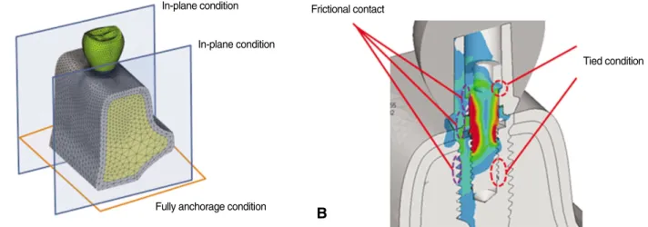
실제 임상의 조건과 가깝도록 하중 조건을 150 N으로 11�로 협측으로 치관의 중심와를 향해서 static loading이 가해지도록 가 정하였다(Fig. 4).21,22경계조건으로는 치근단 쪽은 완전 고정된 것으로, 근원심측으로는 보다 실제에 가까운 골부피를 재현할 수 있는 In-plane 조건을 부여하였다. 지대주 나사와 임플란트 연 결 부위의 최상부와 최하부의 나사선에 tied condition을 부여하 였고, 그 나머지에는 마찰접촉(frictional contact) (μ= 0.5)23,24으로 가 정하였다(Fig. 5).
4. 유한요소 해석
유한요소모델링은 ANSA (Beta Software, Italy)을 이용하였고, 비 선형 유한요소를 해석하는 데는 PAM-MEDISA (ESI group, France)를 사용하였으며 결과분석은 Visual View (ESI group, France)로 해석하였다. 수치해석을 할 때는 Implicit method가 이용 되었다. Mellal 등15은 numerical model들에서 나온 von Mises strain 및 strain energy density와 in vivo data 간에는 일치하였으나 effective stress와는 일치하지 않는다고 주장하였다. 본 연구에서도 in vivo data와 일치하는 von Mises strain을 측정하였다. W군과 S군의 평균을 비교할 때 Levene의 등분산성 검정(equal variance test)을 먼 저 시행한 후 등분산성 여부에 따라 이표본 t-검정(two-sample t-test)를 시행하였으며, 자료의 수가 적고 자료 중에 이상값(out- lier)이 포함되어 있어 Mann-Whitney의 비모수적 검정(Mann- Whitney’s nonparametric test)을 병행하였다.
Fig. 3. The element size near bone-implant interface was 0.1 - 0.12 mm for more reality, the one of the distant zone from the interface was 0.3 - 0.5 mm for mod- el simplification.
0.1 - 0.12 mm
0.18 - 0.2 mm
0.3 - 0.5 mm
Fig. 4. Loading condition applied 150 N at 11 degree angle relative to the lingual cusp.
150 N 11�
Table 1. Mechanical properties of bone, implant, and prosthetic materials Material Young’s moduls (GPa) Possion’s ratio
Cortical bone 13 0.3
Dense trabecular bone 2.6 0.3
Implant 110 0.3
Abutment 90 0.3
Abutment screw 90 0.3
Crown 11.7 0.3
결과
두 가지의 골-임플란트접촉율(40, 70%)에서 S군과 W군 간의 평균을 모수적 방법으로 비교했을 때는 골-임플란트접촉율에 상관없이 등분산 가정이 타당하였고(40% : P=.922, 70% : P=.425) 평균을 비교해 보면, 골-임플란트접촉율이 40%에서는 평균의 차이가 없었고(P=.903) 70%에서도 마찬가지로 차이가 없었다 (P=.981). 또한 비모수적방법으로 비교했을 때도 동일하게 골-임 플란트 접촉율이 40, 70% 각각에서 P=.796, P=.739로 평균의 차이 가 없었다(Table 2, Fig. 6).
임플란트 디자인에 따른 S군과 W군을 비교했을 때 MK III Bra�nemark�에서는 W군의 산포가 더 컸으며, Inplant�에서는 오히 려 W군이 S군에 비해 산포가 더 작았다(Table 3, Fig. 7). 임플란트 디자인에 따른 S군과 W군의 평균을 비교하는데 있어서 모수
적 방법으로 평균을 비교했을 때 MK III Bra�nemark�에서는 등분 산 가정이 타당하나(P=.678) Inplant�에서는 타당하지 않았으며 (P=.0368), MK III Bra�nemark�와 Inplant�의 von Mises strain의 평균 의 차이가 없었고(MK III Bra�nemark�: P=.683, Inplant�: P=.579), 마 찬가지로, 비모수적 방법으로 검정하였을 때도 차이가 없었다 Fig. 5. Constraints of bone model and implant-abutment interface. A: boundary condition of bone model, B: tied condition and frictional contact between abutment and abutment screw.
A B
In-plane condition
In-plane condition
Fully anchorage condition
Frictional contact
Tied condition
Fig. 6. Comparison between S (segmentally randomized osseointegration) and W (wholly randomized osseointegration) group according to osseointegraton degrees (40, 70%). ‘osseo’is osseointegration degree and ‘attach M’is attachment method of bone-implant contact.
Table 2. Averages and standard deviations of von Mises strain in terms of osseointegration degrees (40, 70%). ‘osseo’is osseointegration degree and
‘attach M’is attachment method of bone-implant contact
Osseo attach M Number Average Standard deviation
40 S 10 .007722 .002052
W 10 .007606 .002137
70 S 10 .006001 .001800
W 10 .006019 .001469
(MK III Bra�nemark�: P=.631, Inplant�: P=.971).
골-임플란트 접촉율과 임플란트 디자인을 포함하여 전체적 으로 S군과 W군을 비교했을 때도 Levene의 등분산 검정결과 두 집단(S/W)의 분산이 동일하였으며(P=.898), 두 집단의 평균도 통 계적으로 유의하게 다르지 않았다(P=.939). 또 본 연구의 자료에 서는 outlier를 갖고 있을 뿐만 아니라 정규분포를 벗어나 있으 므로 비모수적 검정이 더 타당할 것으로 추정되며 이 검정결 과는 두 집단 간의 평균이 유의성 있는 차이가 없었다(P=.904, Fig. 8).
한편, S군과 W군 간의 평균이 유의하게 차이가 나지 않기 때 문에 두 집단(S군, W군)을 묶으면 골-임플란트 접촉율이 40% 일 때는 von Mises strain이 7664 ± 2040 μm/m 이고, 70% 일 때는 6009
± 1508 μm/m 으로 골-임플란트 접촉율이 70% 보다 40%에서 von Mises strain이 유의하게 낮았다(P=.007). 골-임플란트 접촉율이 40%일 때 MK III Bra�nemark�의 경우(8385 ± 2184 μm/m)보다 Inplant�의 경우(6942 ± 1690 μm/m)에서 von Mises strain이 낮았으 나 통계적으로 유의한 차이는 아니었다(P=.116). 골-임플란트 접촉율이 70%일 때 Inplant�에서는 4886 ± 1034 μm/m, MK III Bra�nemark�에서는 7134 ± 1232 μm/m로서 Inplant�의 von Mises strain 이 MK III Bra�nemark�의 것보다 유의하게 낮았다(P<.0001).
고찰
Slaets 등25,26은 토끼실험에서 피질골보다 해면골에서 골-임플 란트 접촉율(bone-implant contact)이 초창기에 증가하나 Sennerby 등27은 6주 후에는 오히려 피질골에서 더 높았다고 보고하였다.
또한, Lin 등28은 경골(tibia)에 피질골과 해면골에 해당하는 부 위의 임플란트에 구멍(canals)을 만든 후에 4주 후에 조직학적 검 사를 시행했는데 피질골에 해당하는 구멍에서 해면골에 해당 하는 구멍부위보다 골-임플란트 접촉율이 상당히 높았다. 위 에서 언급한 연구들25-28에 나온 토끼모형이 다른 동물모형(개, 원숭이)과 달리 해면골의 골밀도가 상당히 낮은 것으로 보인 Fig. 7. Comparison between S (segmentally randomized osseointegration) and W (wholly randomized osseointegration) group according to implant design. ‘attach M’
is attachment method of bone-implant contact.
Table 3. Averages (Standard deviations) of von Mises strain in terms of implant design (MK III Bra�nemark�; BI, Inplant�; II). ‘attach M’is attachment method of bone-implant contact
Implant.design attach M Number Average SD
BI S 10 .007585 .001676
W 10 .007934 .002070
II S 10 .006138 .002263
W 10 .005690 .001022
Fig. 8. Comparison between S (segmentally randomized osseointegration) and W (wholly randomized osseointegration) group including osseointegration degree and implant design. ‘attach M’is attachment method of bone-implant contact.
장류모형(primate model)에서 피질골과 해면골을 분리하여 골-임 플란트 접촉율을 연구한 것이 없어서 본 연구에서는 피질골과 해면골의 골-임플란트 접촉율이 같다고 가정하였다. Lin 등28과 Tada 등29의 연구결과를 보았을 때 피질골이 차지하는 영역이 해면골이 차지하는 영역에 비해서는 매우 작으므로 해서 골변 형에 영향을 거의 미치지 않았던 것으로 보였는데, 이 결과는 본 연구에서 피질골과 해면골의 골-임플란트 접촉율을 동일하 게 가정한 것이 실제에 가까운 단순화임을 뒷받침하고 있다.
실제적으로 해면골의 상당한 부분과 골과 임플란트 접촉이 없는 영역(non-osseointegration area)에 골수(bone marrow), 결합조 직(connective tissue), 혈관 등이 개재해 있고, 기존의 골-임플란트 접촉율에 관한 연구들4,7,8에서는 골-임플란트 계면에 존재하는 이 영역에만 결합조직의 탄성계수를 부여하였다. 그럼에도 불 구하고 기존 연구들4,7,8의 한계점은 유한요소법을 연구한 모든 연구와 마찬가지로 골조직의 구조가 매우 복잡하므로 골조직 이 아닌 모든 영역(골수, 결합조직, 혈관 등)에 대해서 결합조직 탄성계수의 조건으로 가정하지는 못하였고 골-임플란트계면 에만 결합조직으로 처리하였으며 또, 이 요소의 크기는 Sato 등30 이 추천한 600 μm 미만보다 훨씬 큰 1000 μm이상의 크기였다. 본 연구에서는 위에서 언급한 한계점을 최소화하면서 효과적인 모형의 단순화를 위해서 골-임플란트 계면 주변의 요소의 크 기는 100 μm로 정하고 그 계면에서 가장 멀리 떨어진 부위의 요 소크기도 300 - 500 μm로 이산화하였고 골-임플란트 접촉이 없 는 영역은 단순화를 위해 결합조직 대신 즉시하중의 조건인 마찰접촉(frictional contact)을 부여하였다(Figs. 3, 5). 지금까지 모 든 유한요소모형들이 비골조직(골수, 결합조직, 혈관 등)을 배 제하고 기존의 기계적인 특성을 연구한 문헌을 근거로 한 탄성 계수를 이용한 골이 전체모형을 차지하도록 가정하므로 해서 실제적인 골보다 더 단단하게 가정된다고 할 수 있다.
Pessoa 등6은 즉시 하중을 가하였을 때 Morse-taper connection 임 플란트에서 internal and external hex connecion의 임플란트보다 더 큰 골변형(strain)을 보인다고 하였고, 반면에 골유착을 가정 한 모형에서는 internal and external hex connection의 임플란트보다 Morse taper 임플란트에서 상당히 낮은 골변형수치가 나왔다고 보고하였고, 이는 Morse taper connection이 보다 임플란트 하방으 로 하중을 분산하기 때문으로 추정하였다. 본 연구에서도 40%
골-임플란트 접촉율일 때는 external hex의 MK III Bra�nemark�과 Morse-taper의 Inplant�의 변형율이 유사하였으나 70%에서는 Inplant�가 MK III Bra�nemark�의 변형율 보다 상당히 낮아진 것은 Pessoa 등6의 연구와 일치한다고 할 수 있고 Morse taper의 임플란 트가 골접촉율이 증가할수록 골흡수에 유리하다고 예측할 수 있다.
결론
제한된 유한요소분석 내에서 다음과 같은 결론을 내릴 수
1. 골-임플란트 접촉율에 상관없이 W군과 S군 간 maximum von Mises strain이 유의성 있는 차이가 없었다.
2. 임플란트 디자인에 상관없이 W군과 S군 간 maximum von Mises strain이 유의성 있는 차이가 없었다.
3. 골-임플란트 접촉율이 40%에서 70%로 증가할 때 maximum von Mises strain은 유의성 있게 감소하였다.
4. External hex의 MK III Bra�nemark�의 peak von Mises strain이 Morse- taper의 Inplant�의 것보다 유의성 있게 높았다.
참고문헌
1. Roberts WE. Bone tissue interface. Int J Oral Implantol 1988;5:71-4.
2. Block MS, Finger IM, Fontenot MG, Kent JN. Loaded hydrox- ylapatite-coated and grit-blasted titanium implants in dogs. Int J Oral Maxillofac Implants 1989;4:219-25.
3. Coelho PG, Marin C, Granato R, Suzuki M. Histomorphologic analy- sis of 30 plateau root form implants retrieved after 8 to 13 years in function. A human retrieval study. J Biomed Mater Res B Appl Biomater 2009;91:975-9.
4. Papavasiliou G, Kamposiora P, Bayne SC, Felton DA. 3D-FEA of osseointegration percentages and patterns on implant-bone interfacial stresses. J Dent 1997;25:485-91.
5. Huang HL, Hsu JT, Fuh LJ, Tu MG, Ko CC, Shen YW. Bone stress and interfacial sliding analysis of implant designs on an immediately loaded maxillary implant: a non-linear finite element study. J Dent 2008;36:409-17.
6. Pessoa RS, Muraru L, Ju′nior EM, Vaz LG, Sloten JV, Duyck J, Jaecques SV. Influence of implant connection type on the bio- mechanical environment of immediately placed implants - CT-based nonlinear, three-dimensional finite element analysis. Clin Implant Dent Relat Res 2010;12:219-34.
7. Lian Z, Guan H, Ivanovski S, Loo YC, Johnson NW, Zhang H.
Effect of bone to implant contact percentage on bone remodel- ling surrounding a dental implant. Int J Oral Maxillofac Surg 2010;
39:690-8.
8. Deng B, Tan KB, Liu GR, Lu Y. Influence of osseointegration de- gree and pattern on resonance frequency in the assessment of den- tal implant stability using finite element analysis. Int J Oral Maxillofac Implants 2008;23:1082-8.
9. Sennerby L, Ericson LE, Thomsen P, Lekholm U, Astrand P. Structure of the bone-titanium interface in retrieved clinical oral implants.
Clin Oral Implants Res 1991;2:103-11.
10. Garetto LP, Chen J, Parr JA, Roberts WE. Remodeling dynamics of bone supporting rigidly fixed titanium implants: a histomorphometric comparison in four species including humans. Implant Dent 1995;4:235-43.
11. Degidi M, Perrotti V, Strocchi R, Piattelli A, Iezzi G. Is insertion torque correlated to bone-implant contact percentage in the early healing period? A histological and histomorphometrical evalua- tion of 17 human-retrieved dental implants. Clin Oral Implants Res 2009;20:778-81.
12. Holmes DC, Loftus JT. Influence of bone quality on stress distribution for endosseous implants. J Oral Implantol 1997;23:104-11.
13. Lin CL, Wang JC, Ramp LC, Liu PR. Biomechanical response of implant systems placed in the maxillary posterior region under var- ious conditions of angulation, bone density, and loading. Int J Oral Maxillofac Implants 2008;23:57-64.
14. Rubin PJ, Rakotomanana RL, Leyvraz PF, Zysset PK, Curnier A, Heegaard JH. Frictional interface micromotions and anisotropic stress distribution in a femoral total hip component. J Biomech 1993;26:725-39.
15. Mellal A, Wiskott HW, Botsis J, Scherrer SS, Belser UC.
Stimulating effect of implant loading on surrounding bone.
Comparison of three numerical models and validation by in vivo data. Clin Oral Implants Res 2004;15:239-48.
16. Ramos A, Simões JA. Tetrahedral versus hexahedral finite elements in numerical modelling of the proximal femur. Med Eng Phys 2006;28:916-24.
17. Rho JY, Ashman RB, Turner CH. Young’s modulus of trabecular and cortical bone material: ultrasonic and microtensile measure- ments. J Biomech 1993;26:111-9.
18. Meyer U, Vollmer D, Bourauel C, Joos U. Sensitivity analysis of bone geometries around oral implants upon bone loading using fi- nite element method. Comp Meth Biomech Biomed Eng 2001;3:553-59.
19. Van Staden RC, Guan H, Loo YC. Application of the finite element method in dental implant research. Comput Methods Biomech Biomed Engin 2006;9:257-70.
20. Geng JP, Tan KB, Liu GR. Application of finite element analysis in implant dentistry: a review of the literature. J Prosthet Dent 2001;85:585-98.
21. Hattori Y, Satoh C, Kunieda T, Endoh R, Hisamatsu H, Watanabe M. Bite forces and their resultants during forceful intercuspal clench- ing in humans. J Biomech 2009;42:1533-8.
22. Chou HY, Jagodnik JJ, Mu¨ftu¨S. Predictions of bone remodeling around dental implant systems. J Biomech 2008;41:1365-73.
23. Merz BR, Hunenbart S, Belser UC. Mechanics of the implant-abut- ment connection: an 8-degree taper compared to a butt joint connection. Int J Oral Maxillofac Implants 2000;15:519-26.
24. Steinemann SG, Mausli PA, Szmukler-Moncler S. Betatitanium alloy for surgical implants. In: Froes FH, Caplan I, eds. Titanium’
92 Science and technology. Warrendale, PA: The Minerals, Metals & Materials Society, 1993. pp. 2689-96.
25. Slaets E, Carmeliet G, Naert I, Duyck J. Early cellular responses in cortical bone healing around unloaded titanium implants: an an- imal study. J Periodontol 2006;77:1015-24.
26. Slaets E, Carmeliet G, Naert I, Duyck J. Early trabecular bone heal- ing around titanium implants: a histologic study in rabbits. J Periodontol 2007;78:510-7.
27. Sennerby L, Thomsen P, Ericson LE. A morphometric and bio- mechanic comparison of titanium implants inserted in rabbit cortical and cancellous bone. Int J Oral Maxillofac Implants 1992;7:62-71.
28. Lin CL, Wang JC, Ramp LC, Liu PR. Biomechanical response of implant systems placed in the maxillary posterior region under var- ious conditions of angulation, bone density, and loading. Int J Oral Maxillofac Implants 2008;23:57-64.
29. Tada S, Stegaroiu R, Kitamura E, Miyakawa O, Kusakari H. Influence of implant design and bone quality on stress/strain distribution in bone around implants: a 3-dimensional finite element analysis. Int J Oral Maxillofac Implants 2003;18:357-68.
30. Sato Y, Wadamoto M, Tsuga K, Teixeira ER. The effectiveness of element downsizing on a three-dimensional finite element mod- el of bone trabeculae in implant biomechanics. J Oral Rehabil 1999;26:288-91.
Effect of bone-implant contact pattern on bone strain distribution:
finite element method study
Dong-Ki Yoo1
, DDS, MSD, Seong-Kyun Kim
1, DDS, PhD, Jai-Young Koak
1, DDS, PhD,
Jinheum Kim2, MS, PhD, Seong-Joo Heo
1*, DDS, PhD1Department of Prosthodontics, School of Dentistry, Seoul National University, Seoul,
2Department of Applied Statistics, University of Suwon, Suwon, Korea
Purpose: To date most of finite element analysis assumed the presence of 100% contact between bone and implant, which is inconsistent with clinical reality. In human retrieval study bone-implant contact (BIC) ratio ranged from 20 to 80%. The objective of this study was to explore the influence of bone-implant contact pattern on bone of the inter- face using nonlinear 3-dimensional finite element analysis. Materials and methods: A computer tomography-based finite element models with two types of implant (Mark III Bra�nemark�, Inplant�) which placed in the maxillary 2ndpremolar area were constructed. Two different degrees of bone-implant contact ratio (40, 70%) each implant design were simulated. 5 finite element models were constructed each bone-implant contact ratio and implant design, and sum of models was 40. The position of bone-implant con- tact was determined according to random shuffle method. Elements of bone-implant contact in group W (wholly randomized osseointegration) was randomly selected in terms of total implant length including cortical and cancellous bone, while ones in group S (segmentally randomized osseointegration) was randomly selected each 0.75 mm verti- cally and horizontally. Results: Maximum von Mises strain between group W and group S was not significantly different regardless of bone-implant contact ratio and implant design (P=.939). Peak von Mises strain of 40% BIC was significantly lower than one of 70% BIC (P=.007). There was no significant difference between Mark III Bra�nemark� and Inplant�in 40% BIC, while average of peak von Mises strain for Inplant�was significantly lower (4886 ± 1034 μm/m) compared with MK III Bra�nemark�(7134 ± 1232 μm/m) in BIC 70% (P<.0001). Conclusion: Assuming bone-implant contact in finite element method, whether the contact elements in bone were wholly randomly or segmentally ran- domly selected using random shuffle method, both methods could be effective to be no significant difference regardless of sample size. (J Korean Acad Prosthodont 2011;49:214-21) Key words: FEA, Bone-implant contact, Implant, Implant design, Randomized osseointegration
*Corresponding Author: Seong-Joo Heo
Department of Prosthodontics and Dental Research Institute, School of Dentistry, Seoul National University, 28 Yeungun-dong, Chongno-gu, Seoul, 110-749, Korea + 82 2 2072 2661: e-mail, [email protected]
Article history
Received April 25, 2011 / Last Revision April 27, 2011 / Accepted July 8, 2011