한국표면공학회지 J. Korean Inst. Surf. Eng.
Vol. 52, No. 6, 2019.
https://doi.org/10.5695/JKISE.2019.52.6.321
<연구논문>
ISSN 1225-8024(Print) ISSN 2288-8403(Online)
입자 핵연료의 SiC/C 다층 도포층의 미세조직 및 극미세 경도 평가
최 용*
단국대학교 신소재공학과
Microstructure and Nano-hardness of SiC/C Multi-coated Layers on a Particulate Nuclear Fuel
Young Choi*
Department of Materials Science and Engineering, Dankook University 119 Dandae-ro, Dongnam-gu, Cheonan-si, Chungnam 31116, Republic of Korea
(Received 20 November, 2019 ; accepted 23 December, 2019)
Abstract
Triso-type coating layers of silicon carbide and graphite on UO
2paticulate nuclear fuel were prepared by using fluidized bed type chemical vapor deposition and self-propagating high temperature synthesis meth- ods to make a coated nuclear fuel of a power plant for hydrogen mass-production. The source and carrier gases were the mixture of methyltrichlorosilane and propane, and inert argon. Chemical analysis and micro- structure observation showed that the coated layers were inner graphite, middle silicon carbide and outer graphite. The elastic modulus and nano-hardness of the silicon carbide layer were 503 [GPa] and 36 [GPa], respectively.
Keywoards: Multi-layer coating, SiC/C, Particulate nuclear fuel
1. 서 론
수소가 청정 에너지원으로 검토됨에 따라서 수소 를 대량생산하기 위한 수소생산용 원자로가 미래형 원자로로서 주목을 받고 있다. 현재 고려중인 수소 생산용 원자로는 고온가스로(high temperature gas cooled reactor)로서 입자형 피복 핵연료를 사용하고 있다[1]. 고온가스로는 작동 온도가 높기 때문에 고 연소도(high burn-up)이며 핵분열 기체 생성물(fission gas)이 많이 발생된다. 이와 같은 이유로 고온 가스 로용 핵연료는 도포 핵연료 입자를 사용한다. 현재 개발 중인 고온 가스로용 도포 핵연료는 일반적으
로 직경이 약 0.6 mm의 UO2 또는 UC의 소결체 입 자를 사용하고 있다 고온가스로의 고연소도와 핵분 열 생성물에 의한 부피 팽창에 대응하기 위하여 내 부는 다공질(porous structure)의 열분해 탄소 (pyrolytic carbon, PyC)로 구성된 버퍼층 (buffer layer)이며 중간층은 도포층의 강도를 유지하고 핵 분열생성물의 확산을 억제할 목적으로 탄화규소 (silicon carbide)와 외부층은 강도를 유지할 목적으 로 고밀도 등방형 열분해 탄소 (high density isotropic pyrolytic carbon)를 도포하고 있다[2].
이와 같은 다층의 도포 핵연료는 유동로형 (fluidized bed type) 증착 장치를 이용하여 화학적 증착법(chemical vapor deposition, CVD) 또는 고온 연소합성법(combustion synthesis)으로 제조되고 있 다[3,4]. 화학적증착법은 열분해된 규소와 탄소가 반 응로에서 탄화규소로 반응하면서 도포가 되는 공정 이다. 탄화규소 층의 특성은 원료 기체의 종류와 화
*
Corresponding Author: Young Choi
119, Dandae-ro, Dongnam-gu, Cheonan-si, Chungcheongnam- do, 31116 Republic of Korea
Tel: +82-41-550-3537 ; Fax: +82-41-559-7866
E-mail: [email protected]
(C)간의 일종의 고온 반응을 통하여 탄화규소(SiC) 를 합성하는 신공정이다. 여기서 탄화규소의 합성 에서 발생되는 약 -67 KJ/mole의 반응열을 활용하 여 탄화규소(SiC)층을 만든다[7]. 일반적으로 탄화 규소의 특성은 연소반응속도에 의한 미세조직과 관 련 있다고 보고되어 있다. 따라서 본 연구의 목적 은 고온자전 연소합성법을 이용하여 도포핵연료 제 조에 적용하여 UO2 입자 핵연료에 열분해 탄소와 탄화규소가 도포된 피복 핵연료를 제조하고 도포층 의 미세조직 관찰과 나노-경도를 평가하는데 있다.
이를 통하여 피복 입자 핵연료를 제조공정에 대한 국내 고유 기술을 확보하고자 한다.
2. 실험 방법
입자형 UO2핵연료 소결체를 전처리를 위하여 120oC 관상로(Thermcraft, USA)에서 건조시킨 후 도포를 수행하였다. 열분해 탄소(C)와 규소(Si)의 도 포는 유동로형 화학증착장치 (fluidized bed type chemical vapor deposition unit)를 이용하여 각각 1050oC와 1550oC 구역에서 메탄가스와 메칠삼염화 실렌(methyltrichlorosilane, CH3SiCl3)을 열분해하여 수행하였다. 가동 조건은 표 1과 같다. 이후 반응 로의 온도를 1750oC로 상승시켜서 잔류 규소와 열 분해 탄송의 고온자전연소합성 반응을 시켰다.
피복 입자 핵연료의 도포층은 주사전자현미경 (CX-200TA, Coxem, Korea)과 고효율 주자전자현미 경(JSM-6400, Jeol, Japan)으로 관찰하였으며 상분 석과 원소분석은 각각 X-선 회절기 (Ultima IV, Rigaku, Japan)와 에너지 분산 분광기(EDS, Oxford, UK)로 분석하였다. 도포층의 경도와 강성도(stiffness)
30회 반복하고 평균값을 취하였다.
3. 결과 및 고찰
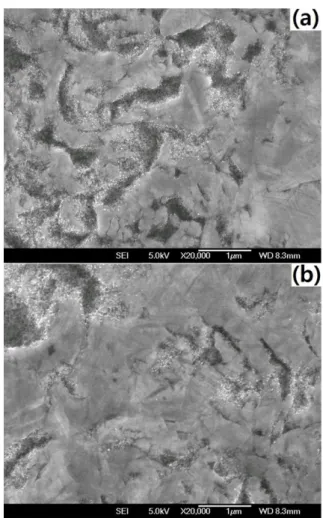
그림 1은 주사전자현미경으로 관찰한 유동형 화 학증착 장치에서 도포후 고온연소반응된 피복 입자 핵연료의 단면 사진이다. 그림 1에서와 같이 구형 입자 핵연료 (fuel kernel) 주위에 버퍼 (buffer), 내 부 열분해 탄소층(inner pyrolytic carbon layer), 탄 화규소층(silicon carbide layer)와 외부 열분해 탄소 층(outer pyrolytic carbon layer)로 구성되어 있으며 각각의 두께는 각각 약 80, 40, 40, 40 μm로 비교 적 균일하게 도포되어 있었다.
그림 2는 피복입자핵연료의 X-선회절 시험 결과 이다. 그림 2에서와 같이 표면의 열분해 탄소의 회
Fig. 1. Cross sectional view of SEM image of a coated nuclear fuel.
Fig. 2. Cross sectional view of SEM image of pyrolytic carbon layer.
Table 1. Typical conditions of fluidized bed type CVD unit preparing for a coated nuclear fuel
deposition temperature [
oC] 1100-1750 total flow rate [l/m] 1.5-2.0 composition of source gas [%] 5-30 total weight of installed specimen [g] 80
sample size [mm] 20
pre-heating temperature [
oC] 400 cone angle of coater [degree] 60
coater size [mm] I.D. 50×300 cone angle of distributer [degree] 60
distributer size [mm] I.D. 23×20
nozzle size [mm] 1.0
절선이 주로 관찰되었다. 열분해 탄소층은 결정립 화 정도에 따라서 크게 등방형(isotropic), 적층형 (laminar), 기둥형(columnar)과 입자형(granular)으로 분류하고 있다[8]. 일반적으로 핵연료를 도포하기 위하여서는 핵분열 생성물을 보호하고 열팽창에 의 한 응력 이완을 위하여서는 등방형 열분해층이어야 한다. 그림 3은 피복핵연료의 열분해 탄소층의 단 면 사진이다. 그림 3에서와 같이 본 연구에서 제조 된 열분해 탄소는 등방형 탄소층임을 알 수 있다.
그림 4는 탄화규소층으로 예측되는 층의 에너지 분산 분광기 (energy dispersive spectroscopy)로 원 소 분석한 결과이다. 그림 5에서와 같이 메칠산염 화실렌이 약 1550oC 부근에서 열분해 되어 규소가 생성되고 탄소와 고온연소합성반응으로 탄화규소층 으로 도포되었음을 보여준다[9].
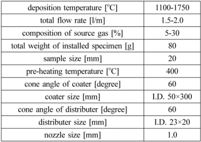
그림 5는 고온자전연소합성 전?후의 피복 핵연료 도포층의 주사전자현미경 사진이다. 그림 5(a)에서 와 같이 규소(SiC)가 도포된 표면은 비교적 균일한 표면을 보이고 있으나 그림 5(b)에서와 같이 고온
자전연소합성된 후에는 미세한 균열과 상대적으로 매끄로운 표면을 갖고 있다. 탄소와 규소가 자전연 소반응으로 탄화규소가 생성되는 기구는 탄소가 탄 화규소 구역으로 확산되는 현상이 율속 단계인 구각 모델(shrinking-core model)과 탄화규소가 액상 규소에 서 석출되는 용해-석출 모델(solution precipitation model)로써 설명되고 있다[10,11]. 구각모델에서는 생성된 탄화 규소층이 확산의 장벽 역할을 하므로 생성물이 성장함에 따라 확산이 어려워져서 반응이 점차 중단되어 반응이 진행되지 않은 잔류 구역(un- reacted area)이 관찰될 수 있다. 그림 6에서와 같이 잔류 구역은 관찰하기 어려웠다. 한편, 용해석출 모 델에서는 국부 농도기울기가 관찰될 수도 있다. 하 지만 규소-탄소의 2원계 상태도를 고려하면 용해도 의 한계가 없고 비화학양론비에 의한 탄화규소가 존재하기 때문에 용해석출에 의한 농도 기울기는 관찰되기 어렵다. 특히 탄화규소층에 탄소원자가 확 산 속도는 규소원자보다 약 100배 빠르기 때문에 규소 층에 탄소가 침투하여 탄화규소가 생성되어도 농도기울기는 존재하기 어렵다. 이는 본 연구의 고
Fig. 4. EDX spectra of silicon carbide layer.
Fig. 3. X-ray spectra of pyrolytic carbon layer.
Fig. 5. SEM images of silicon carbide layers before
and after SHS reaction.
온자전연소합성된 탄화규소 생성기구는 고상-액상 반응에 의하여 액상 규소에 고상의 탄소 원자가 침 투하면서 연소반응에 의하여 탄화규소가 생성되는 용해-석출 모델이 보다 타당성이 있음을 보인다. 따 라서 액상 규소와 고상의 탄소층의 확산 침투에 의 하여 표면이 비교적 매끄러운 상태로 변화하는 한 것으로 예측되며 응고에 다른 열팽창의 차이로 표 면 균열이 생성된 것으로 사료된다.
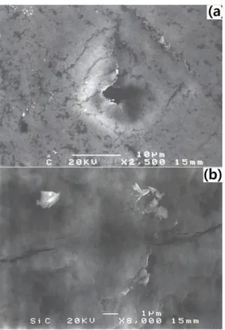
피복 핵연료 도포층의 기계적 특성을 평가하기 위하여 극미세 경도를 측정하여 미세경도와 강성 도(stiffness)를 측정하였다. 그림 6은 탄화규소층과 열분해 탄소층의 압침자의 압흔이다. 그림 6에서 와 같이 동일한 하중에서 비교적 기계적 성질이 낮은 열분해 탄소층은 압흔이 깊게 생성되지만 상 대적으로 단단한 탄화규소층에는 압흔이 얇게 생 성되었다. 본 연구에서는 Oliver-Pharr 모델을 적용 하기 위하여 비교적 단단한 탄화규소의 준-나노 압 침 시험(quasi-nano-indentation test)의 결과를 식 (1)과 식(2)를 적용하여 경도(H)와 강성도(S)를 구 하였다[11].
(1)
여기서 hc=압침 접촉 깊이 (indenter contact depth), Pmax=최대하중, β = 압흔의 기하학적 상수 (indenter geometry value), ε = 물질상수(material constant), A=단면적 이다. 본 연구에서는 탄화규소 의 미세경도와 탄성계수는 각각 36 [GPa]와 503이 었다. 이값은 앞선 연구에서 관찰한 화학적 증착법 (chemical vapor deposition)으로 제조된 탄화규소층 의 값과 유사한 값을 보인다[12].
4. 결 론
수소생산용 고온가스로의 UO2 입자 핵연료의 핵 분열생성물에 의한 고유 안전성을 높이기 위하여 고온 유동로를 사용하여 열분해 탄소와 탄화규소를 도포하고 도포층의 미세조직과 탄화규소층의 준-나 노 경도를 측정하여 다음을 얻었다.
1) 유동형 화학 증착 장치를 사용하여 메탄을 1050oC에서 열분해하며 UO2 입자 핵연료에 도포된 열분해 탄소는 등방형의 미세조직을 갖고 있다.
2) 1050oC-1550oC 구역에서 열분해된 메탄가스와 메칠삼염화실렌에 의하여 생성된 열분해 탄소와 열 분해규소는 자전연소반응하여 용해-석출 모델에 의 하여 탄화규소층을 형성한다.
3) Oliver-Pharr 모델을 적용한 고온연소합성으로 생성된 탄화규소 층의 준-나노 경도와 탄성계수는 각각 36 GPa과 503이다.
감사의 글
자자는 본 연구를 위하여 기술적 도움과 이론적 자문을 준 러시아 IMP(Institute of Metals Physics, RAS)의 Dr. Pirogov와 한국원자력연구원의 이영우 박사, 이정원 박사와 김봉구 박사에게 감사드립니다.
References
[1] D. Olander D, “Nuclear Fuels—Present and Future”. Journal of Nuclear Materials, 389 (2009) pp. 1–22.
[2] N. Rohbeck, D. Tsivoulas, I. P. Shapiro, “In-situ Nano-indentation of Irradiated Silicon Carbide in TRISO Particle Fuel up to 500°C”. Journal of Nuclear Materials, 465 (2015) pp. 692–694.
[3] S. Knol, S. Groot, P. Hania, M. Hannink
“Irradiation of HTR Coated Particles at High Temperatures”, Nuclear Engineering and Design,
hc hmax εβ Pmax---S
⎝ ⎠
⎛ ⎞ –
=