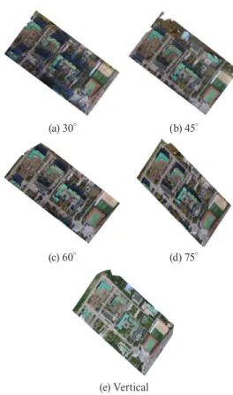
Comparison of Orthophotos and 3D Models Generated by UAV-Based Oblique Images Taken in Various Angles
10
0
0
전체 글
(2)
(3)
(4)
(5)
(6)
(7)
(8)
(9)
(10)
수치
+4
관련 문서
The optimized STL files of the 3D tooth models were imported into the finite element analysis software, CosmosWorks (Structural Research & Analysis
For camera 1, comparison of actual vision data and the estimated vision system model’s values in robot movement stage, based on the EKF method(unit: pixel) ···.. The estimated
Web-based network of career counseling includes the CareerNet developed by the Korea Research Institute for Vocational Education and Training, the Worknet of the Work
other new business models; welcomes, in particular, the development of commercial models that separate consumption from material ownership, in which the function of the
The index is calculated with the latest 5-year auction data of 400 selected Classic, Modern, and Contemporary Chinese painting artists from major auction houses..
1 John Owen, Justification by Faith Alone, in The Works of John Owen, ed. John Bolt, trans. Scott Clark, "Do This and Live: Christ's Active Obedience as the
Table 7 compares the accuracy when all the 100 frame images extracted from three pairs of video data were stitched, when the homography matrix was discretely generated for
Based on the results above, the art therapy centering on modeling contributes to increase of concentration and the concentration period of children with ADHD
