I. Introduction
The technologies in the area of embedded system have advanced exponentially for the last 15 years. Figure 1 illustrates the impro- vements in each field of the technology [1].
Fig. 1. Improvements in mobile computing technology
The exception to the improvements is battery energy density. While the other technologies have improved from 100 times to 4000 times during 13 years, the energy density of battery has increased only 3 times compared to 1990.
Even if the advanced VLSI technology allows us to consume smaller power for the same performance or better, the users are accustomed to transmit or receive more data and use it. As a result, more efficient and durable power system is strongly required in the pervasive computing system area.
In general, an energy harvesting system has a rechargeable battery as a main power source
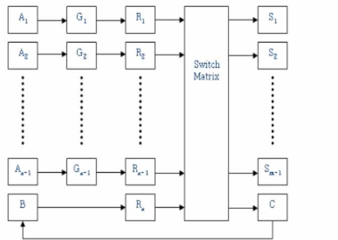
Fig. 2. Energy harvesting system structure (An: ambient energy source, Gn: generators which generates powers from each power source, Rn: regulators, and Sm: subsystems)
* Corresponding Author
Manuscript received April 13, 2006 ; accepted June 13, 2006.
Hyeoungho Bae : MDS Technology
Dong-Sung Kim : Kumoh National Institute of Tech.
This paper was supported by Research Fund, Kumoh National Institute of Technology
Dynamic Power Management Structure for Energy Harvesting Pervasive Computing System
Hyeoungho Bae and Dong-Sung Kim*
Abstract : In this paper, a novel power management structure for an energy harvesting pervasive system is proposed. The system considers the power state of each subsystem to assign proper power sources. The switch matrix structure utilizes each power source to reduce the peak current of the battery. The power management structure can be interfaced to an embedded system power supply without significant design change.
Keywords : Dynamic power management system (DPMS), Energy harvesting pervasive system, Switch matrix structure
and transducers with regulators for ambient energy sources. An energy harvesting system is a kind of MPS (Multiple Power Source) system.
Figure 2 shows a general power supply structure of an energy harvesting system.
From each power source’s state, the switch matrix computes the current that can be drained from the source and assigns the regulators to the subsystems. If each subsystem has power management function, it
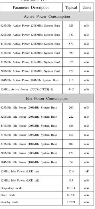
Table 1. Intel PXA270 Power Consumption Spe -cifcations [7]
can have different power state. That is not considered in the previous energy harvesting systems [2, 3, 4, 5, 6].
Table 1 describes the power consumption data of each power state for Intel®PXA270 processor which supports the hardware feature for dynamic power management. The ratio between the most power consuming mode (624MHz active mode) and the least power consuming mode (deep-sleep mode) is over 9000 to 1 [7, 8].
To the best knowledge of the author, a power management structure for the energy harvesting system considering each subsystem power state to assign proper power sources has not been reported on yet in the technical literature.
The paper is organized as follows. Section 2 surveys the related research areas. Section 3 describes the proposed power management structure. Finally, the conclusion and future work are shown in Section 4.
II. Related Researches
In this section, we will survey the related works on MPS (Multiple Power Supply) system, the power sources using ambient energy and power management structure for battery-powe -red system.
The most popular MPS system is the power system of a satellite. The power system composed of solar paddle, rechargeable batteries, power control unit, and power distribution unit [2, 3, 5]. The problem of the system is the solar power can be utilized only if it is powerful enough to drive the entire system. This results from the fact that the battery cannot be charged and discharged at the same time. Anyway the ambient energy cannot be utilized efficiently in the system. To solve this problem, PUMA (Power Utility Maximizer) was proposed [5]. PUMA uses the ambient energy to drive the subsystems even Parameter Description Typical Units
Active Power Consumption
624MHz Active Power (208MHz System Bus) 925 mW
520MHz Active Power (208MHz System Bus) 747 mW
416MHz Active Power (208MHz System Bus) 570 mW
312MHz Active Power (208MHz System Bus) 390 mW
312MHz Active Power (104MHz System Bus) 375 mW
208MHz Active Power (208MHz System Bus) 279 mW
104MHz Active Power(104MHz System Bus) 116 mW
13MHz Active Power (CCCR[CPDIS]=1) 44.2 mW
Idle Power Consumption
624MHz Idle Power (208MHz System Bus) 260 mW
520MHz Idle Power (208MHz System Bus) 222 mW
416MHz Idle Power (208MHz System Bus) 186 mW
312MHz Idle Power (208MHz System Bus) 154 mW
312MHz Idle Power (104MHz System Bus) 109 mW
208MHz Idle Power (208MHz System Bus) 129 mW
104MHz Idle Power (104MHz System Bus) 64 mW
13MHz Idle Power (LCD on) 15.4 mP
13MHz Idle Power (LCD off) 8.5 mW
Deep-sleep mode 0.1014 mW
Sleep mode 0.1630 mW
Standby mode 1.7224 mW
if the power is small to drive the whole system. It elevates the power efficiency over 30% for the sensor node board named DURANODE whose power is supplied from
Table 2. Energy-harvesting opportunities and demonstrated capabilities [4]
a solar paddle and a rechargeable battery [5].
The problem of the previous MPS systems is the lack of consideration on subsystem power state change.
The solar powered calculators and self- winding electric watches are the most famous devices using the ambient energy. The energy sources like above example can supply from few micro-watt to few hundreds milli-watt of power. In the table 2, the performances of various ambient energy sources are described [4].
Still the ambient energy sources are adequate for applications using small amounts of continuous power or large amounts of short period power [6]. This supplement can supply power to the subsystems in the idle state or charge the battery in the system being used for short periods of time [6]. Still the ambient power sources are not used for the main power source of larger embedded system than
the sensor node system. However, the power generated from the ambient light, hand generator, and heel strike is usable level in the embedded systems including the wearable computers. In the near future, the power systems of the pervasive computing system like wearable computer can be MPS system using the ambient power sources.
For efficient use of the ambient power sources in the complex embedded systems like the wearable computers, a power manager should monitor each subsystem’s power state and assigns the appropriate power sources to the subsystems.
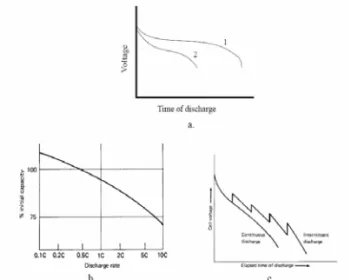
Power management schemes which consider the non-ideal characteristics of the batteries were proposed earlier [9, 10, 11, 12, 13]. In Figure 3, the typical non-ideal properties of batteries are described. The voltage level changes as the discharge time elapses (Figure 3.(a)). The initial capacity of the battery decreases as the intensity of discharge current increases (Rate capacity effect, Figure 3.(b)).
The constant current discharge can be overcome when the discharge is pulsed
Fig. 3. Non-ideal battery properties:
(a) voltage change, (b) loss of capacity, and (c) recovery [10]
(Recovery effect, Figure 3.(c)) [10, 12].
In Martin’s paper, they did experiments for Energy source Performance
Ambient radio
frequency <1 W/ cmμ 2
Ambient light
100mW/cm2(directly toward bright sun) 100 W/cmμ 2(illuminated office)
Thermoelectric 60 W/ cmμ 2
Vibrational microgenerators
4 W/cmμ 3(human motion-Hz) 800 W/cmμ 3 (machine motion-kHz)
Ambient airflow 1mW/cm2
Push buttons 50 J/Nμ
Hand generators 30W/kg
Heel strike 7W potentially available (1cm deflection at 70kg per 1Hz walk)
power profile shown in Figure 4 to find out the effect of reducing active power (A), reducing idle power (B), and reducing duty cycle (C) with Doyle’s battery model (the waveform A, B, and C consume the same average power).
The profile C consumed the least battery power among the three power profiles [10].
Fig. 4. Dynamic power profile example [10]
Recent researches on power management system have been focused on the non-ideal battery characteristics. These are done for both hardware and software area. In hardware area, the structure of power supply to reduce the current drain of each battery cell was proposed [9]. In the software area, the scheduling algorithm for reducing active power was investigated [11, 13]. The ambient energy source can reduce the active current of the battery.
.
Ⅲ Dynamic Power Management Structure
DPMS (Dynamic Power Management Structure) is the power management system which does optimal assignment of the energy source to the subsystems using the information of the external energy sources’ state and the power state of the subsystems.
In this paper, we propose two methods to extend the battery life time. The first one is source paralleling to reduce the peak current which is drained from the battery (New method for the case 1 in Figure 5). The second one is the switch matrix structure which can use the ambient source power efficiently to
Fig. 5. Proposed power management concept
charge the battery (New method for the case 2 in Figure 3). In Figure 5, the shaded box denotes the power requirement of the subsystem.
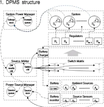
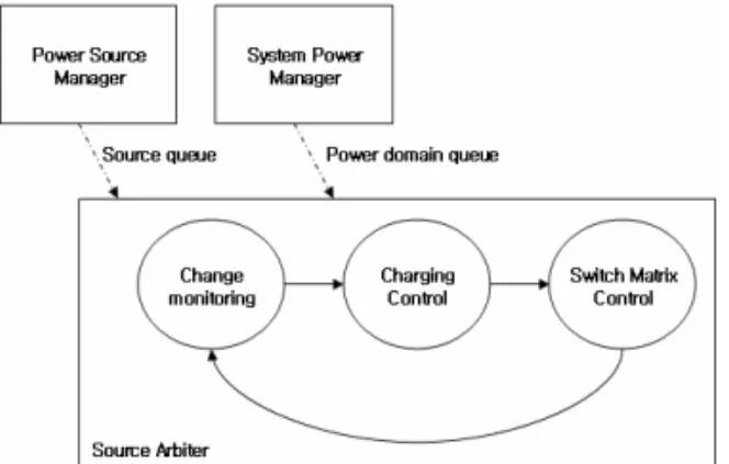
Fig. 6. DPMS structure
The proposed DPMS structure is shown in Figure 6. The composition and functions of each part are described as follow.
A. System Power Manager
Subsystem Monitor: Monitors power st
①
-ates of each subsystem and tran -smits the data to the source arbiter and power source manager.
Power Domain Queue: Calculates requi
②
-red power for each power domain
and hand overs the information to source arbiter.
B. Power Source Manager
Source Monitor: Monitors the ambient
①
energy sources and the battery from the sensors and transmits the energy source state information to the source arbiter and the system power manager.
Source Queue: Calculate estimated am
②
-ount of power extracted from its power sources and transmits the information to source arbiter.
C. Source Arbiter
Switch Matrix Controller: Assigns the
①
available source to the subsystems according to the information from the system power manager and the power source manager.
Switch Controller: Does switch matrix
②
control.
The system power manager decides the whole system power state and monitors the power state of each source. The manager can use hardware signals like battery fault indicator to let the subsystems to enter the sleep mode or shut down mode. The function of each subsystem after the indication is up to
Fig. 7. Switch matrix controller
its power management system. The DPMS system will be the last one to enter the shut-down mode.
The source arbiter is the one of important parts of DPMS with the switch matrix structure. The switch matrix controller module in the Source Arbiter is composed of the source queue, the power domain queue, and the assignment part (Figure 7).
Available power sources are piled up in the source queue. And the power requirements of the subsystems are sorted according to their power domain (required voltage level). If the total sum of the ambient power is enough to supply the whole system power, the battery is excluded from the source queue. In that case, the charger can be placed in the regulator queue. The operation of the charger is decided by the battery manager in the power source manager. By the switch assignment algorithm, the elements in the source queue and in the power domain queue are matched (Figure 8).
The order of queuing is not important in the case of switch assignment algorithm.
Because the main idea of DPSM is treating various ambient power sources as one large chunk of power source. The structure of switch matrix facilitates the use of ambient power sources.
Fig. 8. Switch assignment algorithm
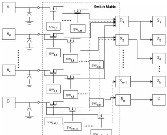
In Figure 9, the structure of proposed switch matrix is provided, where An denotes an ambient power source, B for the battery, swn,m for a switch control signal, Rm denotes a regulator, Sk for a subsystem and C for the charger.
The switch matrix position of DPMS is different to the previous MPS system. When compared to Figure 2, the switch matrix part is located before the regulator part. All the subsystems except the charger are assigned to the regulators statically according to the voltages they use. The charger uses its own regulator. Because the power plane structure of recent embedded system composed according to the voltage level, the switch matrix can be interfaced to recent embedded system power supply without significant design change. The switch controls the current flow from the sources. The output path of the switch is connected to all the regulators except the path from the battery to the regulator for the charger. By turning on the switch, each energy source can be directly connected to all of the regulators. At any moment, one regulator is connected to one power source and the duty ratio of the switch time is controlled according to the available power of each power source and requirement of the power domain.
Fig. 9. DPMS switch matrix structure
The main assumption of this structure is that the output voltage of each sources are large enough to drive the regulators. Especially for standard buck regulator, the input voltage level of the regulator should be higher than that of required output voltage.
The dimension of the switch is defined by
the following equation.
× In Figure 9, the switch matrix has a dimension of × . For general commercial embedded system, power regulator number does not exceed 5. If we assume the number of the usable ambient energy source is under 4 (according to Table 2). The dimension of the switch matrix will be under 24.
There are two main functions of the switch matrix. One is arbitration of the available sources to each regulator according to the dynamic change of power demands of each subsystem. The arbitration function is handled by the source assignment module described in the previous section 3.2. Another function is reducing current drain from the battery. The paralleling of the power sources will reduce the peak battery load current to extend the battery life time [9, 10]. The switch matrix makes the sources supply power to the regulators in parallel. Even if an ambient power source can not drive any subsystems with its own power, it can supply power to reduce current extraction from the battery.
IV. Conclusion
This paper presented a novel power management structure for energy harvesting system. This power management system can be easily interfaced to commercial embedded systems. Since it considers both the source state and the subsystem power state respectively, it can cope more actively with the dynamic change of the ambient energy source and the battery. Therefore it will increase the energy efficiency of the system.
The source paralleling function in the source arbiter can decrease the peak load current of the battery. This increases the battery life time. The dimension of the proposed switch matrix is feasible to commercial embedded systems. For those embedded systems, the matrix structure can be
composed of switches less than 24.
As a future direction of this work, one may consider the improvement of the DPMS structure with partial charge/discharge cycle increasing. The effect of the cycle increase will be investigated in the simulation with proper battery model.
References
Biography
Bae, Hyeoungho
He received his B.S and M.S. degree in Electrical and Computer Eng. from the Seoul National Univ., Korea, in 1999 and 2001 respectively. From March 2001 to current, he works as a hardware engineer in MDS Technology, Korea. His current main research interests are energy harvesting system and low power circuit design.
Email: [email protected] Kim, Dong-Sung
He received his Ph.D. degree in Electrical and Computer Eng. from the Seoul National Uni., Korea, in 2003.
From March 2003 to February 2005, he worked as a postdoctoral researcher in the School of Electrical and Computer Eng. at Cornell Uni., U.S.A. Since 2004, he has been an assistant professor in the School of Electronic Engineering at Kumoh National Institute of Technology, Korea. His current main research interests are networked embedded system, and industrial communication system.
Email: [email protected]