http://dx.doi.org/10.6111/JKCGCT.2013.23.5.230
Fabrication of ATO thin film for IR-cut off by sol-gel method
Jin-Ho Kim†, Kwang-Hee Lee*, Mi-Jai Lee, Jonghee Hwang and Tae-Young Lim
Korea Institute of Ceramic Engineering and Technology, Optic & Display Material Team, Seoul 153-801, Korea
*DO Co., Ltd., Daejeon 305-500, Korea (Received September 16, 2013)
(Revised October 2, 2013) (Accepted October 8, 2013)
Abstract IR cut-off thin films consisted of ATO nanoparticles were successfully fabricated by sol-gel method. The coating solution was synthesized with organic/inorganic hybrid binder and ATO colloidal solution and ATO thin films were coated on a slide glass with the withdrawal speed of 5~40 mm/s. As the withdrawal speed increased from 5 mm/s to 40 mm/s, the thickness of coating thin films also increased from 1.05µm to 4.25 µm and the IR cut-off in wavelength of 780~2500 nm increased from 49.5 % to 66.7 %. In addition, the pencil hardness of ATO thin films dried at 80oC was ca. 5H and the coating films were not removed after a cross cutter tape test because of the hybrid binder synthesized with tetraethylorthosilicate and methyltrimethoxysilane. The surface morphologies, optical properties and film thickness of prepared thin films with a different withdrawal speed were measured by field emission scanning electron microscope (FE- SEM), UV-Vis spectrophotometer, and Dektak.
Key words IR-cut off, Thin film, Coating, Transmittance, Sol-gel
솔-젤 법에 의한 적외선 차단 ATO 박막 제조
김진호†, 이광희*, 이미재, 황종희, 임태영
한국세라믹기술원 광·디스플레이소재센터, 서울, 153-801
*디오, 대전, 305-500 (2013년 9월 16일 접수) (2013년 10월 2일 심사완료) (2013년 10월 8일 게재확정)
요 약 ATO 나노 입자들로 구성된 적외선 차단 박막이 솔-젤 법에 의해 성공적으로 제조되었다. 코팅액은 유무기 하이 브리드 바인더와 콜로이드 ATO 용액으로 합성되었고 ATO 박막은 슬라이드 유리기판에 5~40 mm/s의 인상속도로 코팅되었 다. 인상속도가 5 mm/s에서 40 mm/s로 증가함에 따라 코팅막의 두께 또한 1.05 µm에서 4.25 µm로 증가하였다. 그리고 파장 780 nm에서 2500 nm에서의 적외선 차단율은 49.5 %에서 66.7 %로 증가하였다. 또한 80oC에서 건조된 ATO 박막의 연필경 도 값은 5H를 나타내었고 tetraethylorthosilicate와 methyltrimethoxysilane을 합성한 하이브리드 바인더의 영향으로 테이프테 스트 후 코팅막은 벗겨지지 않았다. 서로 다른 인상속도에 의해 제조된 박막의 표면구조, 광학적 특성 그리고 박막두께는 FE-SEM, UV-Vis-NIR 분광기 그리고 Dektak에 의해 측정되었다.
1.
서 론최근 건물의 고층화와 일반 상용빌딩 벽면의 35~80 % 정도가 유리 창호로 바뀜에 따라 건물의 에너지 손실은 증가하고 있다. 창호 유리는 다른 외피구조에 비해 일사 취득의 이점이 있지만 열적으로 가장 취약하기 때문에
여름철 실내열의 침입은 창유리의 경우 약 70 % 이상이 며, 겨울철 열방출은 50 % 이상이다.
창유리의 광차단 특성을 개선하는 방법으로는 유리에 금속이온을 도입, 금속증기 증착, 광차단제 코팅 그리고 광차단 코팅 필름을 접착시키는 방법이 있다. 이런 방법 들 중에 Sb가 도핑된 SnO2(ATO) 코팅막은 가시광 영역 에서 높은 투과율을 보일 뿐만 아니라, 적외선을 흡수하 여 차단하는 특성을 보이는 좋은 재료이다[1, 2]. 그러므 로 ATO 코팅 필름은 건물의 에너지 절감을 위한 저방 사 창호 유리에 많이 사용되고 있다[3].
†Corresponding author
†Tel: +82-2-3282-2435
†Fax: +82-2-3282-7814
†E-mail: [email protected]
ATO 코팅막을 제조하기 위해서 sol-gel[4, 5], sputtering [6-8], spray pyrolysis[9, 10], laser deposition[11, 12], plasma[13], oblique angle deposition[14] 등의 방법들이 이용되고 있는데, 특히 sol-gel 방법은 저가의 단순공정 이며 코팅막의 두께 및 미세구조의 제어가 용이하기 때 문에 많이 사용되고 있다[15, 16].
고내구성 적외선 차단 ATO막을 제조하기 위해서는 코팅막 중에 함유된 ATO의 함량을 제어하여 열차단 효 과와 가시광 투과율을 조절해야 하며 코팅막의 내구성을 향상시키기 위한 하이브리드 바인더가 필요하다.
본 연구에서는 고내구성 열차단 ATO 코팅막을 제조 하기 위하여 sol-gel법을 이용하여 하이브리드 바인더를 합성하고 ATO 나노입자를 분산시켜 딥코팅 속도에 따 른 박막의 미세구조, 두께변화, 광차단/투과율 및 유리 기판과의 밀착력을 측정하였다.
2.
실험방법ATO 코팅막을 제조하기 위한 하이브리드 바인더 용액 의 합성을 위하여tetraethylorthosilicate(TEOS, Aldrich, 99 %) 15 g과 methyltrimethoxysilane(MTES, Aldrich, 99 %) 7 g을 에탄올 28 g과 혼합한 후 30분간 교반하였 다. 그 후, 0.1 N HCl을 가수분해 촉매로 사용하여 혼합 액에 7 g을 투입하여 3시간 동안 상온에서 반응시켜 폴 리실록산 타입의 유무기 하이브리드 바인더 용액을 제조 하였다.
제조된 폴리실록산 타입의 유무기 하이브리드 바인더 용액 50 g과 antimony tin oxide(ATO) 나노입자 분산액 (D50: 40 nm, 용제: ethoxyethanol, 고형분 30 %) 50 g 을 혼합하였다. 용액의 ATO 나노 입자의 분산성을 향상 시키기 위하여 분산제로 polydimethylsiloxane를 1.0 g 첨가한 후 1시간 혼합하여 IR 차단 코팅 용액을 제조하 였다.
코팅 기판으로는 슬라이드 글래스(t = 1.0 mm)를 사용 하였으며 dip coater를 이용하여 5~40 mm/s 의 인상속도 로 각각의 기판 위에 ATO 막을 코팅하였다. Dip coating 을 통해 얻어진 시편은 80oC에서 1시간 동안 건조하였 다. ATO 코팅액 합성과 박막 제조 모식도를 Fig. 1에 나타내었다.
제조된 박막의 표면 미세구조를 확인하기 위하여 field emission scanning electron microscope(S-4800, HITACHI) 를 사용하였다. 딥코팅의 인상속도에 따른 ATO 박막의 광학적 특성 변화를 분석하기 위하여 자외선-가시광선- 근적외선 분광광도계(UV/VIS/NIR spectrophotometer, V-570, JASCO)를 이용하여 투과율을 측정하였다. 코팅 막의 두께는 Dektak(150, VEECO)을 사용하여 측정하
였으며 코팅막의 연필경도 측정은 pencil hardness tester (CT-PC2, 코아테크)를 사용하여 하중 1.0 kg에서 실시하 였다. 코팅막과 기판과의 밀착력을 확인하기 위하여 3M 스카치테이프(#610)를 사용하여 cross cutter tape test를 실시하였다.
3.
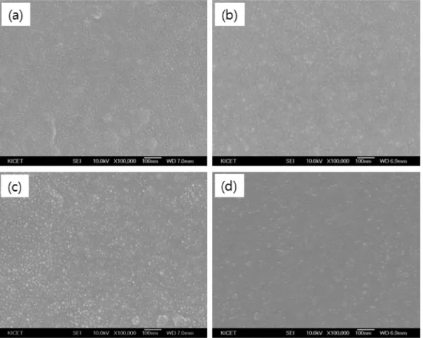
결과 및 고찰Fig. 2는 딥코팅의 인상속도가 5, 10, 20, 40 mm/s로 증가됨에 따라 제조된 ATO 코팅막의 미세구조를 나타 낸다. 그림에서 보듯이 인상속도의 증가에 따른 표면의 차이는 크게 보이지 않지만 수십 나노 정도의 입자들이 치밀한 구조로 형성되어 있는 것을 알 수 있다. 평균 크 기가 40 nm인 ATO 입자가 코팅막의 표면에서 확인이 안 되는 것은 하이브리드 바인더와 입자가 잘 혼합이 되 었고 코팅막의 표면에 바인더가 잘 코팅되었기 때문이다.
Fig. 3은 인상속도의 증가에 따른 코팅막의 두께 변화 를 나타낸다. 인상속도가 5 mm/s에서 40 mm/s로 높아짐 에 따라 제조된 코팅막의 두께는 약 1.05, 2.15, 3.18, 4.25µm로 각각 증가하였다. 동일한 점도의 용액을 사용할 때 인상속도가 증가됨에 따라 코팅막의 두께가 향상된다 는 사실과 일치한다. 제조된 용액의 점도는 약 3.98 cPs로 확인되었다.
Fig. 4는 인상속도의 증가에 따른 코팅막의 자외선 200 nm부터 적외선 영역 2500 nm까지의 투과율을 나타 낸다. 인상속도가 증가함에 따라 가시광 영역에서의 투 Fig. 1. Flow diagram for fabricating ATO thin film by a sol-gel
method.
과율은 감소하며 800 nm 이상에서의 적외선 투과율도 감소하는 결과를 보인다. 이 결과는 Fig. 3에서 확인된 것과 같이 코팅막의 두께가 증가하면 코팅막의 푸른색을 보이는 ATO 성분이 늘어나서 가시광 투과율은 줄어들고 적외선 차단율은 증가하는 것이다. 인상속도에 따라 제조 된 ATO 코팅막의 광학적 특성을 Table 1에 나타내었다.
인상속도가 5 mm/s에서 40 mm/s로 증가됨에 따라 자외 선 영역(200~380 nm)에서의 평균 차단율은 약 32.5 %에 서 47.6 %로 증가되었으며 가시광 영역(380~780 nm)에 서의 평균 가시광 투과율은 83.6 %에서 68.9 %로 감소 하였다. 반면 적외선 영역(780~2500 nm)에서의 적외선 Fig. 2. FE-SEM images of ATO thin films as a function of withdrawal speed: (a) 5 mm/s, (b) 10 mm/s, (c) 20 mm/s and (d) 40 mm/s.
Fig. 3. Thickness of ATO thin films as a function of withdrawal speed: (a) 5 mm/s, (b) 10 mm/s, (c) 20 mm/s and (d) 40 mm/s.
Fig. 4. Transmittance of ATO thin films as a function of with- drawal speed: (a) 5 mm/s, (b) 10 mm/s, (c) 20 mm/s and (d)
40 mm/s.
평균 차단율은 49.5 %에서 66.7 %로 증가하였다.
제조된 ATO 코팅막의 표면 강도를 확인하기 위하여 연필경도를 확인한 결과를 Fig. 5에 나타내었다. 5H 연 필을 사용하여 테스트한 후 광학현미경으로 확인한 결과, Fig. 5(a)에서 보듯이 코팅막 표면에 막의 파손 현상이 나타나지 않았지만, 6H 연필을 사용하여 테스트한 결과 Fig. 5(b)에서 알 수 있듯이 코팅면이 파손되는 결과를 확인하였다. 그러므로 본 연구에서 제조된 ATO 코팅막 은 연필경도 5H 정도의 특성을 나타내었다. 또한 기판 과의 밀착력을 확인하기 위하여 3M 스카치테이프(#610) 를 사용하여 cross cutter tape test한 결과를 Fig. 6에 나타내었다. 그림에서 보듯이 약 1 mm 간격으로 코팅막 을 자른후 스카치테이프를 붙인 후 때어낸 결과 코팅막 이 벗겨지지 않은 것으로 확인되었다. 그러므로 ASTM D 3359 측정 규격에 코팅막이 벗겨지지 않는 5B 등급 에 해당하는 것으로 확인되었다. 딥코팅 후 저온 80oC에 서 건조하여 제조한 코팅막이 5H와 5B 정도의 우수한 강도와 밀착력을 보이는 결과는 본 연구에서 제조한 유 무기 하이브리드 바인더의 내구성이 우수하기 때문이다.
4.
결 론적외선 차단을 위한 코팅막을 sol-gel법을 이용하여 제 조 하였다. 코팅막의 강도와 밀착력을 향상시키기 위하 여 tetraethylorthosilicate와 methyltrimethoxysilane 가수
분해 촉매로 HCl을 사용하여 폴리실록산 타입의 유무기 하이브리드 바인더 용액을 합성하였고 ATO 나노 입자 를 용액에 분산시켜 코팅액을 제조 한 후 딥코팅하여 열 차단 ATO 코팅막을 제조 하였다. 제조된 코팅막은 매우 치밀한 표면 구조를 나타내었으며, 인상속도가 5, 10, 20, 40 mm/s로 높아짐에 따라 제조된 코팅막의 두께는 약 1.05, 2.15, 3.18, 4.25 µm로 각각 증가하였다. 또한 인상속도가 증가함에 따라 코팅막의 가시광 투과율은 83.6 %에서 68.9 %로 감소하였고 반면 적외선 차단율은 49.5 %에서 66.7 %로 증가하였다. 하이브리드 바인더를 사용한 결과 제조된 코팅막의 연필경도는 5H를 나타내 었고 cross cutter tape test 결과 5B 등급의 우수한 밀 착력을 보였다.
감사의 글
본 연구는 한국에너지기술평가원 에너지자원기술개발 Table 1
Optical propeties of fabricated ATO thin films
Sample UV-cut off (%) Vis Transmittance (%) IR-cut off (%)
5 mm/s 32.5 83.6 49.5
10 mm/s 35.3 81.5 52.4
20 mm/s 38.3 74.6 58.3
40 mm/s 47.6 68.9 66.7
Fig. 6. Cross cut test image of ATO thin film fabricated with withdrawal speed of 5 mm/s.
Fig. 5. Pencil test images of ATO thin film fabricated with withdrawal speed of 5 mm/s.
사업 ‘제로에너지 대응 주거용 건물의 복합외피시스템 실증사업’의 연구비 지원으로 수행되었습니다.
참 고 문 헌
[ 1 ] C. Goebbert, R. Nonninger, M.A. Aegerter and H.
Schmidt, “Wet chemical deposition of ATO and ITO coatings using crystalline nanoparticles redispersable in solutions”, Thin Solid Films 351 (1999) 79.
[ 2 ] C. Terrier, J.P. Chatelon and J.A. Roger, “Electrical and optical properties of Sb : SnO2 thin films obtained by the sol-gel method”, Thin Solid Films 295 (1997) 95.
[ 3 ] H. Ohsaki and Y. Kokubu, “Global market and technol- ogy trends on coated glass for architectural, automotive and display applications”, Thin Solid Films 351 (1999) 1.
[ 4 ] X. Chen, “Synthesis and characterization of ATO/SiO2
nanocomposite coating obtained by sol-gel method”, Materials Letters 59 (2005) 1239.
[ 5 ] S.W. Kim, Y.W. Shin, D.S. Bae, J.H. Lee, J. Kim and H.W. Lee, “The effect of the amorphous insulator layer on conduction behaviors of the silicayindium tin oxide two-layer films”, Thin Solid Films 437 (2003) 242.
[ 6 ] J. Monteron, C. Guillén and J. Herrero, “Discharge power dependence of structural, optical and electrical properties of DC sputtered antimony doped tin oxide (ATO) films”, Solar Energy Materials & Solar Cells 95 (2011) 2113.
[ 7 ] W. Yang, S. Yu, Y. Zhang and W. Zhang, “Properties of Sb-doped SnO2 transparent conductive thin films depos- ited by radio-frequency magnetron sputtering”, Thin Solid Films 542 (2013) 285.
[ 8 ] S.U. Kim, Y.S. Park and B. Hong, “Characterization of transparent ATO conducting films prepared by RF mag-
netron sputtering”, J. Kor. Crystal Growth and Crystal Technology 18 (2008) 76.
[ 9 ] B. Zhang, Y. Tian, J.X. Zhang and W. Cai, “The FTIR studies of SnO2: Sb(ATO) films deposited by spray pyrolysis”, Materials Letters 65 (2011) 1204.
[10] K. Ravichandran and P. Philominathan, “Fabrication of antimony doped tin oxide (ATO) films by an inexpen- sive, simplified spray technique using perfume atom- izer”, Materials Letters 62 (2008) 2980.
[11] C. Marcel, M.S. Hegde, A. Rougier, C. Maugy, C.
Guéry and J.M. Tarascon, “Electrochromic properties of antimony tin oxide (ATO) thin films synthesized by pulsed laser deposition”, Electrochimica Acta 46 (2001) 2097.
[12] F. Chen, N. Li, Q. Shen, C. Wang and L. Zhang, “Fabri- cation of transparent conducting ATO films using the ATO sintered targets by pulsed laser deposition”, Solar Energy Materials & Solar Cells 105 (2012) 153.
[13] D.W. Jung and D.W. Park, “Synthesis of nano-sized antimony-doped tin oxide (ATO) particles using a DC arc plasma jet”, Applied Surface Science 255 (2009) 5409.
[14] X. Xiao, G. Dong, J. Shao, H. He and Z. Fan, “Optical and electrical properties of SnO2: Sb thin films depos- ited by oblique angle deposition”, Applied Surface Sci- ence 256 (2010) 1636.
[15] J. Mazloom, F.E. Ghodsi and M. Gholami, “Fiber-like stripe ATO (SnO2:Sb) nanostructured thin films grown by sol-gel method: Optical, topographical and electrical properties”, Journal of Alloys and Compounds 579 (2013) 384.
[16] G. Guzman, B. Dahmani, J. Puetz and M.A. Aegerter,
“Transparent conducting sol-gel ATO coatings for dis- play applications by an improved dip coating tech- nique”, Thin Solid Films 502 (2006) 281.