Development of Two-Dimensional Scanning Videokymography for Analysis of Vocal Fold Vibration
5
0
0
전체 글
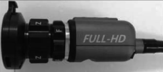
(2) 2D Scanning Videokymography. save the captured images to a video file and the recording times of these systems are relatively short. It is also impossible to obtain synchronized voice feedback from the data and the price of equipment is very expensive.2) In 1996, Svec et al. invented line scanning videokymography, which could be used to observe spatiotemporal images on the fixed horizontal line of the vocal fold with a high cycle resolution of 8000 frames per second.3) This device was cheaper than previous high-speed video laryngoscopy, and it also provided useful information for patients with aperiodic vocal fold vibration, including the absence of vibration, cycle to cycle variability, duration of glottal closure, left-right asymmetry, shape or medial and lateral peak, the laterally traveling mucosal wave, opening versus closing duration, and interference with the vocal folds from the surroundings.3,4) However, it could not be used to observe the whole movement of the entire vocal fold, only supporting information of the vibrating movement on the fixed line of the vocal fold. It was also difficult to determine the distortion caused by patient movement during examination. Although multi-line videokymography, which can process images captured from a high-speed video laryngoscopy, was recently invented to overcome the limitations of line scanning videokyography, but it is also still impossible to observe the entire movement of the whole vocal fold membrane simultaneously.5) To overcome these limitations of previous methods, we developed a new videokymography system for two-dimensional (2D) analysis of the whole vocal fold membrane. Because 2D scanning videokymography can observe the real vibration pattern of the whole vocal fold, distortion problems previously observed with line scanning videokymography can be avoided. Quantitative parameters related to vocal movement can be abstracted from the images, which are captured and saved to a video file by software. We introduce the characteristics and possibilities of the 2D scanning videokymography system.. Materials and Methods 1. Subject The test of the functionality of the 2D scanning videokymography camera was performed in one of the authors (P.H.J 32 years old male). Vocal cord vibrations images were obtained during normal phonation and falsetto phonation. 2. Components of the 2D scanning videokymography system Full HD CMOS(complementary metal oxide semiconduc-. Fig. 1. A full HD CMOS camera was used to make a 2D scanning videokymography system.. tor) image sensor camera was modified in cooperation with HEEAN Co. LTD (Korea) and rigid laryngoscope (Storz, 5.8 mm 8700 CKA, Germany) and A 300-W xenon light source (Storz, NOVA 300 Germany) was used to observe the entire vocal folds (Fig. 1). The system was designed to be able to record the image at full HD (1,920×1,080 pixels) with 30 frames per second. In the study, we used a modified full HD CMOS camera system with a rolling shutter image sensor to invent a new videokymography system. This image sensor captures image lines of the entire frame sequentially from the superior to the inferior portion. The 2D scanning videokymography was developed by allowing temporally different line images among captured frame images. The images of 2D scanning videokymography were displayed in fixed form or moved up and down according to the change in pitch; this was a kind of aliasing phenomenon. 3. Parameters observed Various vocal parameters were observed using 2D scanning videokymography: fundamental frequency (F0), mucosal wave, symmetry of amplitude and phase, opening versus closing duration, shape of medial and lateral peak, non-vibration portion, and cycle aberrations(presence of aberration, ripple, double medial peak, medial unsmoothness).. Results 1. 2D scanning videokymography image In a normal adult male, 2D scanning videokymography was performed during modal phonation and falsetto phonation (Fig. 2). Although the periodic vibration of the vocal fold was displayed variously (fixed or upward and downward), images of the opening, open, closing, and closed phases were displayed on a monitor constantly, as with previous line scanning videokymography. Especially, as the phase proceeded to the closing phase, the distinction between the superior and inferior borders of the vocal fold was observed clearly same as a previous line scanning videokymography.. - 108 -.
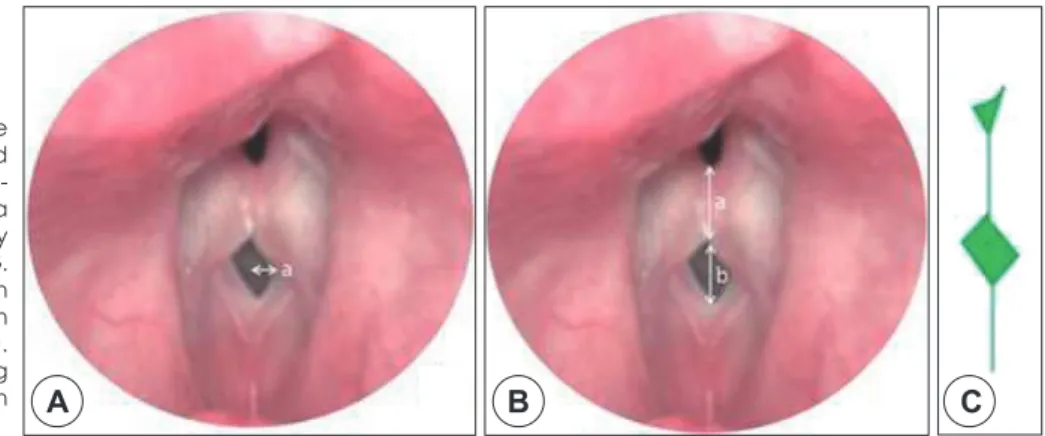
(3) SG Wang, BJ Lee, JC Lee, YS Lim, YM Park, HJ Park, JH Roh, GR Jeon, SB Kwon, BJ Shin. 2. Measurement of fundamental frequency(F0) The fundamental frequency could be calculated as the entire length of the screen divided by the length of the open and closed phases, multiplied by the number of frames per second (the value of 30). In Fig. 3, T indicates the entire length of the screen and T0 indicates a cycle of vocal vibration. Accordingly, the fundamental frequency could be expressed by the formula: Fundamental frequency (F0)=(length of T/length of T0)×30 Hz. Thus, the fundamental frequency in Fig. 3 can. Fig. 2. These images were captured through 2D scanning videokymography during modal phonation in left side and falsetto phonation in right side. The distinction between the superior (b) and inferior borders (a) of the vocal cord could be observed clearly.. T0=1.5 cm. 3. The clinical usefulness of 2D scanning videokymography The mucosal wave of the vocal fold could be observed using. Fig. 4. The mucosal wave of the entire vocal fold could be evaluated in real time. Because the 2D scanning VKG showed the dynamic images of the whole vocal fold in temporally different lines, it was better to evaluate the mucosal wave of the vocal fold.. T=10.5 cm. Fig. 3. Fundamental frequency can be calculated as the entire length of the screen divided by the length of the open phase and close phase, multiplied by the number of frames per second (i.e., 30).. Fig. 5. A : Symmetry of amplitude and phase could be evaluated through dynamic 2D scanning videokymography images. Despite a little difference of phase, it was easy to be found in the 2D canning VKG. B : Opening versus closing duration of one cycle of vocal fold vibration (a: closed phase, b: open phase). C : Schematic drawing describing a mild phase difference between right and left vocal fold.. be calculated by applying the formula above: F0=10.5 cm/1.5 cm×30 frame=210 Hz.. Fig. 6. Shapes of the medial and lateral peak could be evaluated using the 2D scanning videokymography images. This image can be obtained during vocalization or coughing.. A. B - 109 -. C.
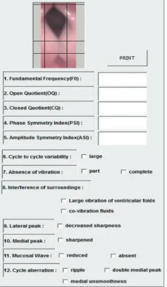
(4) 2D Scanning Videokymography. 2D scanning videokymography in real time (Fig. 4). Symmetry of amplitude and phase could be evaluated using the dynamic 2D scanning videokymography images (Fig. 5A, B). The open and closed phases could be differentiated from each other (Fig. 5B). The medial and lateral peaks of the. A. B. Fig. 7. Shapes of lateral peak could be evaluated using the 2D scanning videokymography images. A : Modal phonation. B : Coughing.. vocal cord could be observed (Fig. 6, 7). Image data of all parameters were displayed on monitor using postprocessing software program (Fig. 8).. Discussion Kymography of vocal fold vibration has been used to capture and record vocal fold movements since the early 1970s. Gall et al.6) used a single lens reflex camera and an indirect laryngoscopic mirror to capture vocal fold movements. The entire area of the vocal fold could be recorded using the instrument as the slit shutter moved in the direction of inferior-tosuperior in the front of the fixed film in the equipment, which was called photokymography (Fig. 9). Using this technique, dynamic images of the entire vocal fold could be acquired, combining several images in serial order captured in different time zones. Then, in 1984, Gall7) devised strip kymography, in which images were acquired while the slit shutter was fixed to one point of the vocal fold and the film was moved rapidly (Fig. 10). In this way, the vertical and horizontal movement of the vocal fold could be observed in detail. This is the principle of modern line scanning videokymography. Videokymography is essentially the implementation of the principle of strip kymography using a charged coupled devices (CCD) video camera. This system was devised to record a fixed horizontal image, and could be used to capture irregular movements of the vocal fold in patients with severe hoarseness. The images that. Moving slit shutter. Fig. 9. Principle of larynx photokymography.. Fixed slit shutter. Fig. 8. Results of captured image data using author created software program.. Fig. 10. Principle of strip kymography.. - 110 -.
(5) SG Wang, BJ Lee, JC Lee, YS Lim, YM Park, HJ Park, JH Roh, GR Jeon, SB Kwon, BJ Shin. were captured continuously could be displayed on a television monitor and saved onto ordinary video tape. However, these techniques were not used widely because it took a long time and was expensive to develop the film and to play it back. Wittenberg et al.,5) introduced digital multi-line kymography to overcome the limitations of line scanning videokymography from Hirose et al., developed a high-speed camera system. In 2007, Qiu and Schutte8) developed real-time line scanning kymography, improving previous line scanning videokymography. It could display color images of the vocal fold and black-and-white images of kymography on the same monitor. Compared to previous videokymography systems, it was a significant improvement, solving the problem of previous models in which the movement of the entire vocal fold could not be observed during examination. However, it was still not possible to evaluate the vibrating portion of the entire vocal fold. In this study, we used a modified full HD CMOS camera system with a rolling shutter image sensor to invent a new videokymography system. This image sensor captures image lines of the entire frame sequentially from the superior to the inferior portion. This rolling process could make skew or leaning artifact on the horizontally moving object, which gives more motion information into the image frame. The 2D scanning videokymography was developed by allowing temporally different line images among captured frame images. The images of 2D scanning videokymography were displayed in fixed form or moved up and down according to the change in pitch. This was a kind of aliasing phenomenon. In cases of the display cycle matched the vibration cycle of the vocal cord, the image was displayed as a fixed form. On the other hand, in cases with discordance between the display cycle and the vibration cycle of the vocal cord, the image would move up or down. The 2D scanning videokymography system could extract dynamic images of the entire vocal fold in real time and analyze the whole vibratory mucosal movement simultaneously. With software designed to measure objective parameters from the dynamic images in our system, almost all variables previously reported by Svec et al.3) could also be obtained, absence of vibration of the vocal fold, duration of glottal closure, leftright asymmetry, shape of lateral peaks, laterally traveling mucosal waves, opening versus closing duration, shape of. medial peaks, cycle aberrations, and interference of the surroundings with the vocal folds. However, it is not possible to measure parameters related to cycle-to-cycle variability in the present system. On the other hand, it could be used to evaluate the non-vibrating portion and the consistency of the vocal fold, which could not be evaluated in line scanning videokymography.. Conclusions In this study, 2D scanning videokymography was developed to evaluate the whole mucosal wave of the entire vocal fold. Various parameters (absence of vibration of vocal fold, duration of glottal closure, left-right asymmetry, shape of lateral peaks, laterally traveling mucosal wave, opening versus closing duration, shape of medial peak, cycle aberrations etc.) could be measured using the system. However, it was not possible to evaluate cycle-to-cycle variability with the current device. In the future, if these parameters can be quantified, the 2D scanning videokymography could be applied to evaluate structural and functional abnormalities of the vocal fold as a new diagnostic tool. S.-G. Wang has received grants from the Pusan National University Research Grant, funded by Pusan National University School of Medicine and Biomedical Research Institute. The rest of the authors declare that they have no relevant conflict of interest.. REFERENCES 1) Casiano RR, Zaveri V, Lundy DS. Efficacy of videostroboscopy in. the diagnosis of voice disorders. Otolaryngol Head Neck Surg 1992; 107:95-100. 2) Hirose H. High speed digital imaging of vocal fold vibration. Acta Otolaryngol Suppl 1988;458:151-3. 3) Svec JG, Schutte HK. Videokymography: high-speed line scanning of vocal fold vibration. J Voice 1996;10:201-5. 4) Svec JG, Sram F, Schutte HK. Videokymography in voice disorders: what to look for? Ann Otol Rhinol Laryngol 2007;116:172-80. 5) Wittenberg T, Tigges M, Mergell P, Eysholdt U. Functional imaging of vocal fold vibration: digital multislice high-speed kymography. J Voice 2000;14:422-42. 6) Gall V, Gall D, Hanson J. Laryngeal-photokymography. Arch Klin Exp Ohren Nasen Kehlkopfheilkd 1971;200:34-41. 7) Gall V. Strip kymography of the glottis. Arch Otorhiolaryngol 1984; 240:287-93. 8) Qiu Q, Schutte HK. Real-time kymographic imaging for visualizing human vocal-fold vibratory function. Rev Sci Instrum 2007;78: 024302.. - 111 -.
(6)
수치
관련 문서
