Vol.19, No.1, (2019), pp.25~30 https://doi.org/10.9714/psac.2019.21.1.025
```
1. INTRODUCTION
High temperature superconducting (HTS) synchronous machine is expected to have advantages of higher efficiency, size and weight reduction compared to conventional permanent magnet rotating machines, hence research has been actively carried out on machine designs and demonstrations for MW-class applications such as large-offshore wind power generators and ship propulsion motors [1-10]. HTS synchronous machines have been designed for various topologies according to the position of HTS field coils and the use of iron cores [11-16]. For most topologies, HTS machines have been designed based on finite element method (FEM) analysis, which has been widely used in conventional electric machine design.
However, in the case of air-cored rotating machines with HTS field coil at rotor, the topology used in many previous demonstration cases, analytic magnetic field calculation is possible based on the Laplace equation solution with approximated configuration [17, 18]. This analytical approach has been used for several design cases [19-22], and more quick and wide design investigation could be done among potential design options due to its relatively short time-consuming calculation. Based on this analytic field calculation, this paper presents a conceptual design method of air-cored HTS synchronous machine using parameter sweep approach. First, parameter sweep approach for HTS machine design is described based on
the analytic parameter calculation module, which is consists of 1) analytic magnetic field calculation, 2) inductance calculation, 3) critical current calculation, 4) size and weight calculation, 5) HTS conductor consumption, and 6) efficiency calculation. With suggested design approach, a 5-MW ship propulsion motor was designed referring to previously developed machines [23- 25], and the analytical magnetic field results is compared with the FEM solution to verify the accuracy of our analytical method.
2. CONCEPTUAL DESIGN METHOD BASED ON PARAMETER SWEEP APPROACH 2.1. Design Flowchart for Parameter Sweep Approach
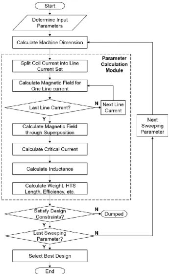
Fig. 1 shows a design flowchart of conceptual design for air-cored synchronous machine. First, when the input parameters are determined, parameter calculations of the machine are performed analytically in the “parameter calculation module” for given machine geometry represented by a set of sweeping parameters. The sweeping parameters are 𝑥, 𝑦, 𝑧, 𝑅𝑠𝑖, 𝑎1, and 𝑎2, and their definition is shown in Fig. 2. After the machine parameter calculation is completed for the previous sweeping parameters set, then the parameter calculation is performed again for the next set of sweeping parameters. In these repetitive calculation process, the designs that satisfy the design constraints among the results of the parameter calculation module are saved in the memory, and the final design that best suits the user’s requirements is selected among them.
A parameter sweep approach for first-cut design of 5 MW Ship propulsion motor
Uijong Bong, Soobin An, Chaemin Im, Jaemin Kim, and Seungyong Hahn*
Department of Electrical and Computer Engineering, Seoul National University, Seoul, 08826, Korea
(Received 15 February 2019; revised or reviewed 14 March 2019; accepted 15 March 2019)
Abstract
This paper presents a conceptual design approach of air-cored synchronous machine with high temperature superconductor (HTS) field winding. With a given configuration of a target machine, boundary conditions are set in the cylindrical coordinate system and analytic field calculation is performed by solving a governing equation. To set proper boundary conditions, current distributions of the field winding and the armature winding are expressed by the Fourier expansion. Based on analytic magnetic field calculation results, key machine parameters are calculated: 1) inductance, 2) critical current of field winding, 3) weight, 4) HTS conductor consumption, and 5) efficiency. To investigate all potential design options, 6 sweeping parameters are determined to characterize the geometry of the machine and the parameter calculation process is performed for each design options. Among design options satisfying constraints including >80 % critical current margin and >95 % efficiency, in this paper, a first-cut design was selected in terms of overall machine weight and HTS conductor consumption to obtain a lightweight and economical design. The goal is to design a 5-MW machine by referring to the same capacity machine that was previously constructed by another group. Our design output is compared with finite element method (FEM) simulation to validate our design approach.
Keywords: HTS synchronous machine, conceptual design, parameter sweep
* Corresponding author: [email protected]
Fig. 1. A design flow chart of parameter sweep approach for first-cut design of HTS synchronous machine.
Parameter calculation based on analytic field solution is iteratively performed for each sweeping parameter sets.
Fig. 2. Two-dimensional schematic of simplified air-cored synchronous machine with the definition of 6 sweeping parameters. Radial and azimuthal position (𝑅 , 𝜃 ) of each components are represented in cylindrical coordinates. Only one pole of the full model is presented based on the symmetry of the machine.
Fig. 3. Azimuthal distribution of one line current of field coil in one pole-pair determined by sweeping parameters 𝑎1 and 𝑎2 satisfying the equation: 𝑎1+ 𝑎2+ 𝑎3= 1. 𝑥 - axis represents electrical angle and 𝑦 -axis represents magnitude of linear current density of one line current.
2.2. Analytic Parameter Calculation of Air-cored HTS Machine
Parameter calculation module in Fig.1 is divided into the following 4 steps: 1) magnetic field calculation; 2) critical current calculation; 3) inductance calculation; 4) weight, efficiency, HTS length, and other parameter calculation.
2.2.1 Magnetic Field Calculation
When the dimension is determined by the sweeping parameters as shown in Fig. 2, the current density distributions in 2-dimensional schematic by the field and armature windings are split into sets of line currents. In cylindrical coordinate (𝑟, 𝜃, 𝑧), the distribution of one line current along the theta direction of the field coil is given as shown in Fig. 3, and expressed by the Fourier expansion as (2). The azimuthal distribution of the line current of the armature coil of 3-phase AC current of (3) at t = 0 is given by (5). 𝑁𝑎, 𝑁𝑓, 𝐼𝑎, 𝐼𝑓, 𝑅𝑎, and 𝑅𝑓 is turns of coil, coil current, and radius of line current for armature coil and field coil each. 𝑝, 𝜔, and 𝑘𝑤𝑛 means, number of pole pairs, angular frequency and packing factor, respectively [26].
𝐾𝑓0= 8𝑁𝑓𝐼𝑓𝑝
𝑛𝜋2𝑅𝑓𝑎1(𝑠𝑖𝑛(𝑛𝜋(2𝑎1+𝑎2)
2 ) − 𝑠𝑖𝑛(𝑛𝜋𝑎2
2 )) (1) 𝐾𝑓(𝜃) = ∑𝐾𝑓0cos(𝑛𝑝𝜃) , 𝑛 = 1,3,5, … (2) 𝑖𝑎𝑚(𝑡) = 𝐼𝑎cos (𝜔𝑡 −2𝜋(𝑚−1)
3 ) , 𝑚 = 1,2,3 (3) 𝐾𝑎0=3𝑁𝑎𝐼𝑎𝑘𝑤𝑛
𝜋𝑅𝑎 (4)
𝐾𝑎(𝜃) = ∑𝐾𝑎0sin(3(𝑛 − 1)𝑝𝜃) , 𝑛 = 1,3,5, … (5)
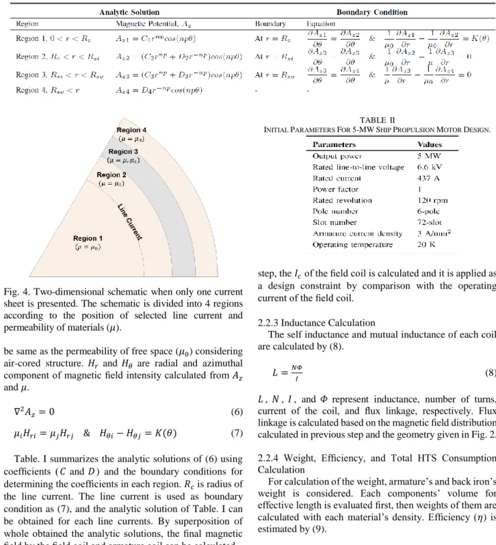
When one line current (𝐾(𝜃)) is selected among the line current sets, the given dimension can be divided into four regions as shown in Fig. 4, and the governing equation and its boundary conditions are given as (6) and (7) [27]. (6) is Laplace’s equation in terms of an axial component of magnetic vector potential (𝐴𝑧). 𝜇 is permeability of materials and its value in region 1, 2 and 4 are assumed to
Fig. 4. Two-dimensional schematic when only one current sheet is presented. The schematic is divided into 4 regions according to the position of selected line current and permeability of materials (𝜇).
be same as the permeability of free space (𝜇0) considering air-cored structure. 𝐻𝑟 and 𝐻𝜃 are radial and azimuthal component of magnetic field intensity calculated from 𝐴𝑧
and 𝜇.
∇2𝐴𝑧= 0 (6) 𝜇𝑖𝐻𝑟𝑖= 𝜇𝑗𝐻𝑟𝑗 & 𝐻𝜃𝑖− 𝐻𝜃𝑗= 𝐾(𝜃) (7)
Table. I summarizes the analytic solutions of (6) using coefficients (𝐶 and 𝐷 ) and the boundary conditions for determining the coefficients in each region. 𝑅𝑐 is radius of the line current. The line current is used as boundary condition as (7), and the analytic solution of Table. I can be obtained for each line currents. By superposition of whole obtained the analytic solutions, the final magnetic field by the field coil and armature coil can be calculated.
2.2.2 Critical Current Calculation based on Measured 𝐼𝑐 Data
After calculating the magnetic field, the critical current 𝐼𝑐(|𝐵|, 𝜃) is calculated considering the magnetic field and the angular dependency [28-30]. 𝐼𝑐 data of the HTS measured at the operating temperature of the motor is used for the calculation. For the saddle type field coil shown in Fig. 2, the radial component of magnetic field (𝐵𝑟) in the cylindrical coordinate is horizontal to the 𝑐-axis of the REBCO tape and the azimuthal component (𝐵𝜃) is perpendicular. Based on 𝐵𝑟 and 𝐵𝜃 calculated in previous
TABLE II
INITIAL PARAMETERS FOR 5-MWSHIP PROPULSION MOTOR DESIGN.
step, the 𝐼𝑐 of the field coil is calculated and it is applied as a design constraint by comparison with the operating current of the field coil.
2.2.3 Inductance Calculation
The self inductance and mutual inductance of each coil are calculated by (8).
𝐿 =𝑁𝛷
𝐼 (8) 𝐿 , 𝑁 , 𝐼 , and 𝛷 represent inductance, number of turns, current of the coil, and flux linkage, respectively. Flux linkage is calculated based on the magnetic field distribution calculated in previous step and the geometry given in Fig. 2.
2.2.4 Weight, Efficiency, and Total HTS Consumption Calculation
For calculation of the weight, armature’s and back iron’s weight is considered. Each components’ volume for effective length is evaluated first, then weights of them are calculated with each material’s density. Efficiency (𝜂) is estimated by (9).
𝜂 =𝑃𝑖𝑛−𝑃𝑐
𝑃𝑖𝑛 (9)
In (9), 𝑃𝑖𝑛 represents input power and 𝑃𝑐 means copper loss.
Total HTS conductor consumption is calculated as the product of the average conductor length of one turn of field winding and the designed turn number of field winding.
For evaluation of the average conductor length of one turn, end- winding length of field winding is also considered.
Calculated weight, efficiency, and HTS consumption can be used as design constraints or as variables of objective function in design selection. The calculations of other parameters are referenced in [17, 20].
TABLE I
ANALYTIC SOLUTIONS AND BOUNDARY CONDITIONS WITH A CURRENT SHEET.
TABLE III
SWEEPING PARAMETERS FOR 5-MWSHIP PROPULSION MOTOR DESIGN.
Fig. 5. Conceptual design results of the parameter sweep for the 5-MW ship propulsion motor represented as scattered plot: (a) the first parameter sweep for wide design investigation; (b) the second parameter sweep for detailed design investigation. For both graphs, the 𝑥-axis shows the required HTS conductor, while 𝑦 -axis the calculated weight.
3. EXAMPLE 5-MW MOTOR DESIGN AND ACCURACY VERIFICATION OF ANALYTIC
PRAMETER CALCULATION
3.1. Input Parameters for 5-MW Motor Design
Based on the conceptual design approach described in section II, a 5-MW 120 rpm ship propulsion motor was designed as an example. The input parameters were determined based on previously designed and fabricated ship propulsion motors as design reference [23-25]. The pole number and slot number were assumed to be 6 and 72,
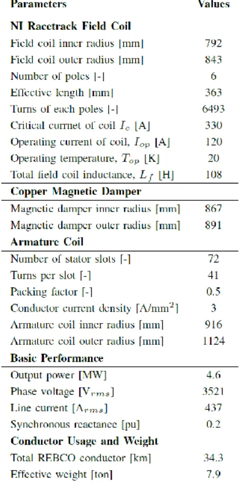
TABLE IV
KEY PARAMETERS OF 5-MWSHIP PROPULSION MOTOR.
and the armature current density was determined to 3 A/mm2. The operating temperature was set at 20 K. The input parameters are summarized in Table. II. Table. III shows the minimum, maximum, and interval of the each sweeping parameters used in parameter sweeps. Two times of parameter sweep were performed: 1) the first parameter sweep for a wide-ranged investigation on design options, 2) the second parameter sweep for detailed investigation on design options. The sweeping range of the second sweeping parameters was determined based on the results of the first parameter sweep that minimized the machine weight and HTS consumption in the first sweep.
3.2. Design Results of 5-MW Ship Propulsion Motor Fig. 5 (a) and Fig. 5 (b) show the results of each parameter sweep. The 𝑥-axis of the graph represents HTS consumption and the 𝑦 -axis represents machine weight.
Each point represents potential design options that satisfy the design constraints. For the first parameter sweep, the weight and the total HTS conductor consumption range from 7.1 to 44.8 tons and from 41 to 307 km, respectively, and from 6.6 to 10.5 tons and from 33 to 48 km for the second parameter sweep. The final selected design option is in the red circle in Fig. 5 (b), which shows second parameter sweep results. The sweeping parameters of the selected design were as follow: (𝑥, 𝑦, 𝑧, 𝑎1, 𝑎2, 𝑅𝑠𝑖) = (0.815, 0.94, 0.75, 0.09, 0.3, 1.14). The key parameters of the selected design calculated by our analytic approach are summarized in Table IV.
Fig. 6. (a) FEM model for designed 5-MW ship propulsion motor and (b) its magnetic field distribution shown in 1/6th model when field coils are fully excited at the rated current of 120 A.
Fig. 7. Azimuthal distribution of radial component of magnetic field at (a) the field coil and (b) the armature coil calculated by analytic method and FEM. The 𝑥 -axis represents the azimuthal electric angle while the 𝑦-axis 𝐵𝑟.
3.3. Comparison between Analytic Parameter Calculation Method and Finite Element Method
For the verification of the parameter calculation module used in the parameter sweep, the results of the analytic calculation and the results of the FEM were compared based on the designed 5-MW ship propulsion motor.
MagNet was used as an FEM program, and Fig. 6 (a) shows constructed FEM model of the motor. The generated magnetic field distribution by the coil currents is seen in Fig. 6 (b). The peak value of magnetic field is calculated to be 4.83 T. Fig. 7 shows a comparison of the magnetic field of the analytic solution and the finite element analysis along the azimuthal direction at the field coil (at 𝑟 = 818
mm) and the armature coil (at 𝑟 = 1020 mm). The 𝑥-axis represents the azimuthal electric angle in cylindrical coordinate and the 𝑦-axis means radial magnetic field (𝐵𝑟).
In Fig. 7, the magnetic radial field distributions due to the analytic solution was calculated to be very similar to the values calculated by FEM in both field coil and armature coil. These results validate our parameter sweep approach based on analytic parameter calculations because machine parameter calculations including critical current, machine outputs, and inductances are mainly based on calculated values of magnetic field.
4. CONCLUSION
A parameter sweep-based design approach for air-cored HTS machine is proposed in this paper. In parameter sweep process, sweeping parameters representing the geometry of the air-cored HTS machine are defined, and key design parameters are analytically calculated for each sweeping parameter sets. The analytic parameter calculation includes calculation of magnetic field distribution, critical current of HTS field coil, inductance of each coils, machine weight, total HTS consumption, and efficiency. For calculation of magnetic field distribution, current distribution by coil is approximated as sets of current sheets, and final magnetic field is obtained by superposition of solution of Laplace equation by each current sheet. Based on suggested design approach, a 5-MW ship propulsion motor was designed with previously designed ship propulsion motors as a reference design, and the analytic and finite element method results of the designed motors were compared. The design approach suggested in this paper could be used for basic design of air-cored HTS rotating machine design.
ACKNOWLEDGMENT
This work was supported by the National Research Foundation of Korea as a part of Mid-Career Research Program (No. 2018R1A2B3009249).
REFERENCES
[1] S. S. Kalsi, K. Weeber, H. Takesue, C. Lewis, H.-W. Neumueller, and R. D. Blaugher, “Development status of rotating machines employing superconducting field windings,” Proc. IEEE, vol. 92, no. 10, pp. 1688–1704, 2004.
[2] T. Yanamoto, M. Izumi, M. Yokoyama, and K. Umemoto, “Electric propulsion motor development for commercial ships in Japan,” Proc.
IEEE, vol. 103, no. 12, pp. 2333–2343, 2015.
[3] G. Snitchler, B. Gamble, and S. S. Kalsi, “The performance of a 5 MW high temperature superconductor ship propulsion motor,”
IEEE Trans. Appl. Supercond., vol. 15, no. 2, pp. 2206–2209, 2005.
[4] K. Umemoto, K. Aizawa, M. Yokoyama, K. Yoshikawa, Y. Kimura, M. Izumi, K. Ohashi, M. Numano, K. Okumura, M. Yamaguchi et al., “ Development of 1 MW-class HTS motor for podded ship propulsion system,” in J. Phys. Conf. Ser., vol. 234, no. 3, IOP Publishing, 2010, p. 032060.
[5] P. N. Barnes, M. D. Sumption, and G. L. Rhoads, “Review of high power density superconducting generators: Present state and prospects for incorporating YBCO windings,” Cryogenics, vol. 45, no. 10-11, pp. 670–686, 2005.
[6] K. S. Haran, S. Kalsi, T. Arndt, H. Karmaker, R. Badcock, B.
Buckley, T. Haugan, M. Izumi, D. Loder, J. W. Bray et al., “High power density superconducting rotating machines—Development status and technology roadmap,” Supercond. Sci. Technol., vol. 30, no. 12, p. 123002, 2017.
[7] S. Fukui, J. Ogawa, T. Sato, O. Tsukamoto, N. Kashima, and S.
Nagaya, “ Study of 10 MW-class wind turbine synchronous generators with HTS field windings,” IEEE Trans. Appl. Supercond., vol. 21, no. 3, p. 1151, 2011.
[8] S. Fukui, T. Kawai, M. Takahashi, J. Ogawa, T. Oka, T. Sato, and O. Tsukamoto, “Numerical study of optimization design of high tem- perature superconducting field winding in 20 MW synchronous motor for ship propulsion,” IEEE Trans. Appl. Supercond., vol. 22, no. 3, p. 5200504, 2012.
[9] A. B. Abrahamsen, N. Mijatovic, E. Seiler, T. Zirngibl, C. Træ holt, P. B. Nørga˚rd, N. F. Pedersen, N. H. Andersen, and J. Ø stergaard,
“Superconducting wind turbine generators,” Supercond. Sci.
Technol., vol. 23, no. 3, p. 034019, 2010.
[10] G. Snitchler, B. Gamble, C. King, and P. Winn, “10 MW class superconductor wind turbine generators,” IEEE Trans. on Appl.
Supercond., vol. 21, no. 3, pp. 1089–1092, 2011.
[11] R. Qu, Y. Liu, and J. Wang, “Review of superconducting generator topologies for direct-drive wind turbines,” IEEE Trans. Appl.
Supercond., vol. 23, no. 3, p. 5201108, 2013.
[12] Y. Terao, M. Sekino, and H. Ohsaki, “Comparison of conventional and superconducting generator concepts for offshore wind turbines,”
IEEE Trans. on Appl. Supercond., vol. 23, no. 3, p. 5200904, 2013.
[13] T. Miller and A. Hughes, “Comparative design and performance analysis of air-cored and iron-cored synchronous machines,” in Proc. Inst. Electr. Eng., vol. 124, no. 2, IET, 1977, pp. 127–132.
[14] Y. Liu, R. Qu, and J. Wang, “Comparative analysis on superconducting direct-drive wind generators with iron teeth and air-gap winding,” IEEE Trans. on Appl. Supercond., vol. 24, no. 3, pp. 1–5, 2014.
[15] B. Gamble, G. Snitchler, and S. S. Kalsi, “HTS generator topologies,” in Power Engineering Society General Meeting, IEEE, 2006, p. 5.
[16] J. Frauenhofer, J. Grundmann, G. Klaus, and W. Nick, “Basic concepts, status, opportunities, and challenges of electrical machines utilizing High-Temperature Superconducting (HTS) windings,” in J. Phys. Conf. Ser., vol. 97, no. 1, IOP Publishing, 2008, p. 012189.
[17] S. S. Kalsi, “Applications of high temperature superconductors to electric power equipment,” John Wiley & Sons, 2011.
[18] A. Hughes and T. Miller, “Analysis of fields and inductances in air- cored and iron-cored synchronous machines,” in Proc. Inst. Electr.
Eng., vol. 124, no. 2, IET, 1977, pp. 121–126.
[19] A. B. Abrahamsen, N. Mijatovic, E. Seiler, M. Sorensen, M. Koch, P. Norgard, N. F. Pedersen, C. Traholt, N. H. Andersen, and J.
Ostergard, “Design study of 10 kW superconducting generator for wind turbine applications,” IEEE Trans. on Appl. Supercond., vol.
19, no. 3, pp. 1678– 1682, 2009.
[20] H. Jang, I. Muta, T. Hoshino, T. Nakamura, S. Kim, M. Sohn, Y.
Kwon, and K. Ryu, “Conceptual design of 100 HP synchronous motor with HTS field winding,” in Proc. Int. Conf. Elect. Eng.
Japan, 2002, pp. 1618–1628.
[21] N. Mijatovic, A. B. Abrahamsen, C. Træ holt, E. Seiler, M.
Henriksen, V. Rodriguez-Zermeno, and N. F. Pedersen,
“Superconducting generators for wind turbines: Design considerations,” in J. Phys. Conf. Ser., vol. 234, no. 3, IOP Publishing, 2010, p. 032038.
[22] U. Bong, S. An, J. Voccio, J. Kim, Y.-G. Kim, K. J. Han, H. Lee, and S. Hahn, “A Design Study on MW-class Synchronous Motor with No-Insulation HTS Field Winding,” IEEE Trans. on Appl.
Supercond., Manuscript accepted for publication.
[23] H. Moon, Y.-C. Kim, H.-J. Park, I.-K. Yu, and M. Park, “An introduction to the design and fabrication progress of a megawatt class 2G HTS motor for the ship propulsion application,” Supercond.
Sci. Technol., vol. 29, no. 3, p. 034009, 2016.
[24] H. Moon, Y.-C. Kim, H.-J. Park, M. Park, and I.-K. Yu,
“Development of a MW-class 2G HTS ship propulsion motor,”
IEEE Trans. Appl. Supercond., vol. 26, no. 4, pp. 1–5, 2016.
[25] B. Gamble, G. Snitchler, and T. MacDonald, “Full power test of a 36.5 MW HTS propulsion motor,” IEEE Trans. Appl. Supercond., vol. 21, no. 3, pp. 1083–1088, 2011.
[26] D. Hu, J. Zou, T. J. Flack, X. Xu, H. Feng, and M. D. Ainslie,
“Analysis of fields in an air-cored superconducting synchronous motor with an HTS racetrack field winding,” arXiv preprint arXiv:1305.3815, 2013.
[27] D. K. Cheng et al., “Field and wave electromagnetics,” Pearson Education India, 1989.
[28] Y. Lee, N. Nakamura, T. Komagome, K. Mizuno, M. Ogata, and K.
Nagashima, “In-field performances of commercial REBCO tapes below liquid nitrogen temperatures,” Physica C, vol. 495, pp. 141–
145, 2013.
[29] C. Senatore, C. Barth, M. Bonura, M. Kulich, and G. Mondonico,
“Field and temperature scaling of the critical current density in commercial REBCO coated conductors,” Supercond. Sci. Technol., vol. 29, no. 1, p. 014002, 2015.
[30] D. Hilton, A. Gavrilin, and U. Trociewitz, “Practical fit functions for transport critical current versus field magnitude and angle data from (RE) BCO coated conductors at fixed low temperatures and in high magnetic fields,” Supercond. Sci. Technol., vol. 28, no. 7, p.
074002, 2014.