Three-dimensional finite element analysis of platform switched implant
Se-Young Moon1, Young-Jun Lim2, Myung-Joo Kim2, Ho-Beom Kwon2*
1School of Dentistry, Seoul National University, Seoul, Republic of Korea
2Dental Research Institute and Department of Prosthodontics, School of Dentistry, Seoul National University, Seoul, Republic of Korea
PURPOSE. The purpose of this study was to analyze the influence of the platform switching concept on an implant system and peri-implant bone using three-dimensional finite element analysis. MATERIALS AND METHODS. Two three-dimensional finite element models for wide platform and platform switching were created. In the wide platform model, a wide platform abutment was connected to a wide platform implant. In the platform switching model, the wide platform abutment of the wide platform model was replaced by a regular platform abutment. A contact condition was set between the implant components. A vertical load of 300 N was applied to the crown. The maximum von Mises stress values and displacements of the two models were compared to analyze the biomechanical behavior of the models. RESULTS. In the two models, the stress was mainly concentrated at the bottom of the abutment and the top surface of the implant in both models. However, the von Mises stress values were much higher in the platform switching model in most of the components, except for the bone. The highest von Mises values and stress distribution pattern of the bone were similar in the two models. The components of the platform switching model showed greater displacement than those of the wide platform model. CONCLUSION. Due to the stress concentration generated in the implant and the prosthodontic components of the platform switched implant, the mechanical complications might occur when platform switching concept is used. [J Adv Prosthodont 2017;9:31-7]
KEYWORDS: Platform switching; Dental implants; Implant abutments; Dental implant-abutment design; Dental implant-abutment interface
INTRODUCTION
Platform switching, also known as diameter shifting, is a tech- nique combining an implant with a reduced diameter abut- ment.1,2 The concept was introduced in the early 1990s after development of a wide diameter implant that was connected to
the standard abutment.2,3-5 Since it was introduced, the tech- nique has been evaluated by many researchers; it was proposed that connecting the smaller diameter abutment to a larger implant could help prevent crestal bone loss.2,6-12 In addition, it is reported that platform switching is beneficial in establishing biological width and produces excellent esthetic results.13-15
Other than the suggestion that platform switched implants produce satisfactory esthetic results, their advantages can be sum- marized in terms of biological and biomechanical aspects.9,10,16-18 Biologically, marginal bone preservation is explained by the change in the micro-gap location, which might be related to inflammatory cell infiltration and reformation of biological width.10,16 The relocation of the micro-gap might serve as a defense mechanism against bacterial penetration and limit inflammation in marginal bone.9,17 In addition, platform switch- ing generates a larger surface area for soft tissue attachment.18
Mechanically, platform switched implants are known to redistribute stress and ultimately affect peri-implant marginal bone loss.19 Stress redistribution is reported to be achieved by centralizing stress.20 It was also stated that prosthetic loading
Corresponding author:
Ho-Beom Kwon
Dental Research Institute and Department of Prosthodontics, School of Dentistry, Seoul National University
101, Daehak-ro, Jongno-gu, Seoul 03080, Republic of Korea Tel. +82220723816: e-mail, [email protected]
Received May 13, 2016 / Last Revision October 26, 2016 / Accepted November 17, 2016
© 2017 The Korean Academy of Prosthodontics
This is an Open Access article distributed under the terms of the Creative Commons Attribution Non-Commercial License (http://creativecommons.
org/licenses/by-nc/3.0) which permits unrestricted non-commercial use, distribution, and reproduction in any medium, provided the original work is properly cited.
This research was supported by Basic Science Research Program through the National Research Foundation of Korea (NRF) funded by the Ministry of Education of Korea (2015R1D1A1A01060940).
forces that transmitted to the bone-implant interface was reduced.20 However, the biomechanical properties of the plat- form switching concept have not been explained clearly and there seems to be no consensus on its mechanical advantages.
Platform switched implants reportedly decrease the stress con- centration on the implant-bone interface, while increasing stress on the abutment and screw.19 In another study, platform switching was found to reduce bone strain.21,22 The value and range of stress concentration decreased as the implant diame- ter increased in a further study.3,23 Previous studies suggested that platform switching reduced stress on the marginal bone crest.24,25 However, some argued that these favorable results were related to the increased diameter of the implant, not the platform switching concept.1 When the platform switching concept was introduced, it was compared with regular platform implants because there was no matching abutment for wide diameter implants.2 Currently, the wide platform implant sys- tem is used clinically and a comparison of platform switched and wide platform implants is necessary. According to a previ- ous study, although the relocation of the micro-gap via plat- form switching affected the mechanical properties of the implant-abutment connection, platform switching did not alter the stress concentration in the bone, suggesting that marginal bone preservation is related to biological advantages, and not platform switching.1,26 This was supported by a study using finite element analysis, in which a circumferential horizontal mismatch of 0.5 mm did not make an important contribution to the biomechanical environment of implants.27
Finite element analysis is a computational method that can calculate the stress and displacement of the structure using dis- cretization.28 One of the advantages of finite element analysis is that the analysis of complex structures is possible. There have been many studies that used finite element analysis to analyze the stress distribution of implants and the surrounding structures.29-31 Finite element analysis has been used to verify the platform switching concept and to show stresses on inter- nal structures.1,19,32
The purpose of this study was to analyze the influence of the platform switching concept, which was thought to have biomechanical advantages in peri-implant bone, using three- dimensional finite element analysis.
MATERIALS AND METHODS
Two three-dimensional finite element models, wide platform
and platform switching models, were designed. They included an external hex implant system and peri-implant bone tissue.
In the wide platform model, a wide platform abutment was connected to a wide platform implant. The platform switching model was created by connecting a regular platform abutment to a wide platform implant. In each model, the implant was placed in a segment of the mandible and a gold crown was placed on the abutment. A vertical load of 300 N was applied on the occlusal surfaces of the crowns. The maximum von Mises stress values and displacements of the components in the two models were compared to analyze the biomechanical behavior of the models.
The models for three-dimensional finite element analysis were assumed to have the implant-prosthesis complex for the mandibular first molar. Finite element models of cortical bone, cancellous bone, implant, abutment, abutment-screw, and crown were separately generated and then combined. The bone block that was similar to the shape of the partial mandible was created using mesh generation software (Visual-Mesh, ESI group, Paris, France). The cancellous bone was surrounded by the cortical bone of approximately 2 mm thickness. To mini- mize the influence of the model size on the results of the finite element analysis, the size of the bone block was deter- mined. The mandible model was designed to be 35 mm in length, 15 mm in width, and 30 mm in height.33 The implant used for finite element model was based on an external hex system, with 5 mm in diameter and 10 mm in height (USII, Osstem, Pusan, Korea). The geometries of the implant system in the Initial Graphics Exchange Specification (IGES) file for- mat were provided by the manufacturer. They were changed to meshes for finite element analysis using meshing software Visual-Mesh (ESI group, Paris, France). During the conversion process from raw geometry data to finite element meshes, the implant and abutment screws were simplified into a cylinder shape for the reduction of calculation time. Tetrahedral mesh- es for the simulation were generated using meshing software (Visual-Mesh, ESI group, Paris, France).
Two finite element models for wide platform and platform switching models were generated. The wide platform model was composed of cortical bone, cancellous bone, a wide diam- eter implant, a wide diameter abutment, an abutment screw, and a crown. The wide diameter abutment had the same exter- nal hex structure as the regular platform abutment. The plat- form switching model had a regular diameter abutment instead of the wide diameter abutment. Except for the abutment, the
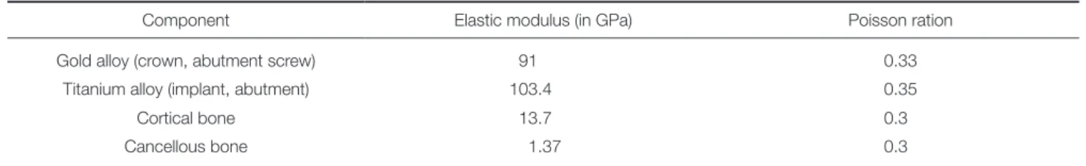
Table 1. Material properties of the materials used in this study
Component Elastic modulus (in GPa) Poisson ration
Gold alloy (crown, abutment screw) 91 0.33
Titanium alloy (implant, abutment) 103.4 0.35
Cortical bone 13.7 0.3
Cancellous bone 1.37 0.3
wide platform model was identical to the platform switching model. For the wide platform model, 21,915 nodes and 86,183 tetrahedral elements were used, and, for the platform switching model, 21,057 nodes and 86,119 elements were used (Fig. 1).
The material properties of each component from previous studies were used.34,35 The materials were assumed to be homo- geneous, isotropic, and linearly elastic. The gold crown and the abutment screw were assumed to be made of gold alloy. For the implant and the abutment, the titanium alloy was used. The material properties used in this study are summarized in Table 1. The medial and distal ends of the mandible segment were constrained in six degrees of freedom. The frictional contact condition was established on the two adjacent surfaces. The surfaces between the top of the implant and the bottom of the abutment was set as frictional contact surface and the coeffi- cient of friction between two components was 0.16.36 The oth- er contact surfaces was located between the lower part of the abutment screw head and the abutment. The coefficient of friction was set to be 0.2.36 Other components were tied to each other at the contact surfaces.
As a loading condition, a total vertical load of 300 N was gradually distributed to the occlusal surfaces of the crowns over 2 milliseconds (Table 2).37 The distributed load was applied at the nodes on the buccal and occlusal surfaces of the crown model.
A simulation was performed using finite element structural analysis software (Virtual Performance, ESI group, Paris, France).
The maximum von Mises values in the components and stress distribution patterns of the wide platform and platform switching model were compared. In addition, the displacement of the components in both models was analyzed.
RESULTS
During the gradual loading period, stress appeared in the com- ponents. At the end of loading, stress concentrations were mainly observed at the bottom of the abutment and on the top surface of the implant in both models. Overall stress distribu- tion patterns were similar between the two models (Fig. 2).
Fig. 1. Finite element models. (A) wide platform model and (B) platform switching model.
Table 2. Gradual loading condition used in this study Time (in millisecond) Force (in N)
0.2 100
0.4 200
0.6 300
2 300
A B
Fig. 2. Overall stress distributions in the models. Stress concentrations were mainly observed at the bottom of the abutment and on the top surface of the implant in both models. (A) wide platform model and (B) platform switching model.
A B
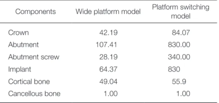
The platform switching model showed higher von Mises stress values in the prosthodontic components than the wide platform model (Fig. 3). Maximum von Mises stress occurred at the abutment in both models. The maximum von Mises stress value of the platform switching model was 830.00 MPa and that of the wide platform model was 107.41 MPa. The highest von Mises stress value of the platform switching model was approximately eight times greater than that of the wide platform model. In other prosthodontic components, platform switching model also showed higher von Mises stress values (Table 3). The maximum von Mises stress value at the crown of platform switching model was 1.99 times higher than that of the wide platform model, 12.06 times higher at the screw, and 12.89 times higher at the implant.
The stress distribution patterns in the prosthesis and implant components were not symmetrical. On the loading side, a higher stress distribution occurred. The contact area between the abutment and implant showed the highest stress concentra- tion among all components in the models. The von Mises stress values in the abutment screws were lower than those in the abutment or implant.
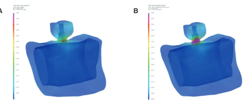
Other than the abutment and the implant, stress concentra- tions were observed at the crown and in cortical bone. In the bone, relatively lower von Mises stress values were observed than those in other components and the highest von Mises stress values and stress distribution patterns of the two models were similar (Fig. 4). In cortical bone of the platform switching model, the von Mises stress values were higher than those in wide platform model, although the difference was not signifi-
Table 3. The highest von Mises stress values (in MPa) in the individual components
Components Wide platform model Platform switching model
Crown 42.19 84.07
Abutment 107.41 830.00
Abutment screw 28.19 340.00
Implant 64.37 830
Cortical bone 49.04 55.9
Cancellous bone 1.00 1.00
Fig. 3. Stress distributions in implants and prosthetic components. The platform switching model showed higher von Mises stress values than the wide platform model. (A) wide platform model and (B) platform switching model.
A B
Fig. 4. Stress distributions in peri-implant bone models. The highest von Mises stress values and stress distribution patterns of the two models were similar. (A) wide platform model and (B) platform switching model.
A B
cant. The highest value of the cortical bone in the platform switching model was 45.25 MPa, and 45.75 MPa in the wide platform model. In both models, the maximum von Mises stress value of cortical bone was higher than that of cancellous bone. In cortical bone, the stress was concentrated around the implant and spread along the upper cortical bone portion. In cancellous bone, the maximum von Mises stress values were 1 MPa in both models and stress concentrations occurred in areas close to the cortical bone and implant.
The maximum displacement occurred in the crowns of the two models. Components of the platform switching model showed greater displacement than those of the wide platform model (Table 4). The maximum displacement of the abutment in the platform switching model was 11.17 times greater than that of the wide platform model. At the abutment screw, the maximum displacement of the platform switching model was 10.73 times greater than that of the wide platform model and 1.21 times greater at the implant. The maximum displacement values in the bone were similar between the models.
DISCUSSION
In this study, there were similar stress distribution patterns in both wide platform and platform switching models. The stress concentration occurred at the abutment-implant interface, and these results were in accordance with the previous studies.1,24,26 However, the platform switching model had different stress distribution features compared to the wide platform model.
The highest von Mises stress values of the abutment, the abut- ment screw, and the implant in the platform switching model were much higher than those in the wide platform model. In the cortical bone, the von Mises stress values in the platform switching model were similar to those in the wide platform model. In the cancellous bone, there was no difference between the models. This means that platform switching might not affect stress in the marginal bone, which is in agreement with the results of the previous studies.26,27 The result that displace- ment of the bone did not vary greatly between the models was also in accordance with other studies.20,27 In several previous studies using finite element analysis, it was reported that plat-
form switching reduced bone strain and affected the stress dis- tribution in the marginal bone, as well as increasing the stress on the abutment and abutment screw.19-21,24 Considering the displacements and stresses in the cortical and cancellous bone and the implant components in this study, there seemed to be no noticeable influence of platform switching on peri-implant bone structure.
The cause of decreased bone resorption of marginal bone in platform switching has been thought to be related to the changes of a biological width,38 inflammatory cells,2 the distance between the implant-abutment gap and the bone crest,39 and stress concentration.40,41 Platform switching has been suggested to be advantageous in preventing bone resorption; one report found that bone resorption in marginal bone was related to overload.41 However, the results of the present study suggested that the change in stress distribution in the platform switched implant might not explain differences in marginal bone resorp- tion, although platform switching could impact the mechanical components of the implant system.26 This is supported by the research suggesting that the reduction of bone stress in the platform switched implant is related to the increased implant diameter, not the platform switching technique.20 Previously reported differences in marginal bone loss in the platform switched implant might be biological in nature rather than bio- mechanical.
The reason why the results in this study varied from other studies reporting decreased stress in bone might be related to differences in methods of finite element analysis. In one study, the contact condition was not set and all of the components were presumed to be bonded completely.24 In another study, separate prosthodontic components did not exist, unrealistic bonding between the components was set, and the occlusal force applied was very small.19 Another explanation for the var- ied results of finite element studies is that, in most of the stud- ies, the concept of preload was not introduced. With preload, stress distribution patterns would be different from that with- out preload.42
In this study, the results showed that displacements and stress distribution patterns of prosthodontic components in the platform switching model were different from those in the wide platform model. Considering these results, the platform switched implant might have mechanical disadvantages com- pared to the wide platform implant, which had larger compo- nents. In the wide platform implant, more favorable mechanical features including a wide external hex structure can be expect- ed. Although there have not been any reports of remarkable drawbacks in using the platform switched implant,27 the stress concentration on the prosthodontic components can be a seri- ous disadvantage. Centralized forces to the axis of the implant might be transmitted through the abutment screw and thus might concentrate stress on implant components, increase the possibility of component fracture, and lead to implant failure.24 Considering the stress concentrations and large displacements of the prosthodontic components in this study, platform switching seemed undesirable in terms of mechanical proper- ties and might lead to mechanical complications including screw loosening and component fracture in implant system.24 Table 4. The maximum displacements of the individual
components in wide platform and platform switching models (in µm)
Components Wide platform model Platform switching model
Crown 34.89 505.89
Abutment 21.39 238.89
Abutment screw 19.77 212.18
Implant 17.49 21.16
Cortical bone 18.12 21.70
Cancellous bone 17.41 20.58
The related stress concentration might be greater due to the increased difference in diameter between the implant and abut- ment interface.19,26 Besides the stress concentration on the prosthodontic components, there might be other disadvantages to the platform switching concept. In platform switching, there is the limitation of having the same screw access hole size and requiring sufficient space for the development of the emer- gence profile.19
Although finite element analysis has been developed since it was first introduced to the dental field, it still has limitations related to reproduction of complex structure, mesh size, boundary conditions, introduction of preload, and non-linear material properties. In this study, the geometry of the implant was simplified for the reduction of calculation time and the convenience of modeling. With the threaded implant design, the stress distribution pattern and the displacements may be dif- ferent because threads can contribute in dissipating stress, increase implant-bone contact area, and resist external force.43,44
Further finite element studies with more sophisticated con- ditions could reveal the quantitative influence of the stress concentration on marginal bone loss in the platform switched implant, accurate structural analysis of platform switching con- cept, and the mechanism of peri-implantitis. Finite element analysis with these advanced features would contribute to solv- ing problems including reproduction of dynamic masticatory simulation and the influence of different restorative materials on the implant system.
CONCLUSION
Although von Mises stress values in the implant components were much higher in the platform switching model than those in the wide platform model, the stress values in the bone of the platform switching model were similar to those of the wide platform model. Biomechanical advantages of the platform switched implant in marginal bone loss was thought to be doubtful. Due to the stress concentration generated in the implant and the prosthodontic components of implant system, the mechanical complications might occur when platform switching concept is used.
ORCID
Se-Young Moon http://orcid.org/0000-0003-1675-0431 Young-Jun Lim http://orcid.org/0000-0003-2504-9671 Myung-Joo Kim http://orcid.org/0000-0003-2020-5284 Ho-Beom Kwon http://orcid.org/0000-0003-4973-7727 REFERENCES
1. Pellizzer EP, Verri FR, Falcón-Antenucci RM, Júnior JF, de Carvalho PS, de Moraes SL, Noritomi PY. Stress analysis in platform-switching implants: a 3-dimensional finite element study. J Oral Implantol 2012;38:587-94.
2. Lazzara RJ, Porter SS. Platform switching: a new concept in implant dentistry for controlling postrestorative crestal bone levels. Int J Periodontics Restorative Dent 2006;26:9-17.
3. Schrotenboer J, Tsao YP, Kinariwala V, Wang HL. Effect of microthreads and platform switching on crestal bone stress levels: a finite element analysis. J Periodontol 2008;79:2166- 72.
4. Duyck J, Slaets E, Sasaguri K, Vandamme K, Naert I. Effect of intermittent loading and surface roughness on peri-im- plant bone formation in a bone chamber model. J Clin Periodontol 2007;34:998-1006.
5. Li T, Kong L, Wang Y, Hu K, Song L, Liu B, Li D, Shao J, Ding Y. Selection of optimal dental implant diameter and length in type IV bone: a three-dimensional finite element analysis. Int J Oral Maxillofac Surg 2009;38:1077-83.
6. Enkling N, Jöhren P, Klimberg T, Mericske-Stern R, Jervøe- Storm PM, Bayer S, Gülden N, Jepsen S. Open or submerged healing of implants with platform switching: a randomized, controlled clinical trial. J Clin Periodontol 2011;38:374-84.
7. Cocchetto R, Traini T, Caddeo F, Celletti R. Evaluation of hard tissue response around wider platform-switched im- plants. Int J Periodontics Restorative Dent 2010;30:163-71.
8. Bilhan H, Mumcu E, Erol S, Kutay O. Influence of platform- switching on marginal bone levels for implants with mandibu- lar overdentures: a retrospective clinical study. Implant Dent 2010;19:250-8.
9. Canullo L, Iurlaro G, Iannello G. Double-blind randomized controlled trial study on post-extraction immediately restored implants using the switching platform concept: soft tissue re- sponse. Preliminary report. Clin Oral Implants Res 2009;20:
414-20.
10. Luongo R, Traini T, Guidone PC, Bianco G, Cocchetto R, Celletti R. Hard and soft tissue responses to the platform- switching technique. Int J Periodontics Restorative Dent 2008;28:551-7.
11. Prosper L, Redaelli S, Pasi M, Zarone F, Radaelli G, Gherlone EF. A randomized prospective multicenter trial evaluating the platform-switching technique for the prevention of postrestorative crestal bone loss. Int J Oral Maxillofac Implants 2009;24:299-308.
12. Trammell K, Geurs NC, O’Neal SJ, Liu PR, Haigh SJ, McNeal S, Kenealy JN, Reddy MS. A prospective, random- ized, controlled comparison of platform-switched and matched-abutment implants in short-span partial denture sit- uations. Int J Periodontics Restorative Dent 2009;29:599-605.
13. Wagenberg B, Froum SJ. Prospective study of 94 platform- switched implants observed from 1992 to 2006. Int J Periodontics Restorative Dent 2010;30:9-17.
14. Calvo-Guirado JL, Ortiz-Ruiz AJ, López-Marí L, Delgado- Ruiz R, Maté-Sánchez J, Bravo Gonzalez LA. Immediate maxillary restoration of single-tooth implants using platform switching for crestal bone preservation: a 12-month study. Int J Oral Maxillofac Implants 2009;24:275-81.
15. Cumbo C, Marigo L, Somma F, La Torre G, Minciacchi I, D’Addona A. Implant platform switching concept: a litera- ture review. Eur Rev Med Pharmacol Sci 2013;17:392-7.
16. Broggini N, McManus LM, Hermann JS, Medina RU, Oates TW, Schenk RK, Buser D, Mellonig JT, Cochran DL. Persistent acute inflammation at the implant-abutment interface. J Dent Res 2003;82:232-7.
17. Rodríguez-Ciurana X, Vela-Nebot X, Segalà-Torres M, Calvo- Guirado JL, Cambra J, Méndez-Blanco V, Tarnow DP. The effect of interimplant distance on the height of the interim- plant bone crest when using platform-switched implants. Int J Periodontics Restorative Dent 2009;29:141-51.
18. Al-Nsour MM, Chan HL, Wang HL. Effect of the platform- switching technique on preservation of peri-implant marginal bone: a systematic review. Int J Oral Maxillofac Implants 2012;27:138-45.
19. Maeda Y, Miura J, Taki I, Sogo M. Biomechanical analysis on platform switching: is there any biomechanical rationale? Clin Oral Implants Res 2007;18:581-4.
20. Hsu JT, Fuh LJ, Lin DJ, Shen YW, Huang HL. Bone strain and interfacial sliding analyses of platform switching and im- plant diameter on an immediately loaded implant: experimen- tal and three-dimensional finite element analyses. J Periodontol 2009;80:1125-32.
21. Wu AY, Lung H, Huang HL, Chee W. Biomechanical investi- gations of the expanded platform-switching concept in im- mediately loaded small diameter implants. J Prosthet Dent 2016;115:20-5.
22. Pessoa RS, Bezerra FJ, Sousa RM, Vander Sloten J, Casati MZ, Jaecques SV. Biomechanical evaluation of platform switching: different mismatch sizes, connection types, and im- plant protocols. J Periodontol 2014;85:1161-71.
23. Baggi L, Cappelloni I, Di Girolamo M, Maceri F, Vairo G.
The influence of implant diameter and length on stress distri- bution of osseointegrated implants related to crestal bone ge- ometry: a three-dimensional finite element analysis. J Prosthet Dent 2008;100:422-31.
24. Tabata LF, Assunção WG, Adelino Ricardo Barão V, de Sousa EA, Gomes EA, Delben JA. Implant platform switching: bio- mechanical approach using two-dimensional finite element analysis. J Craniofac Surg 2010;21:182-7.
25. Himmlová L, Dostálová T, Kácovský A, Konvicková S.
Influence of implant length and diameter on stress distribu- tion: a finite element analysis. J Prosthet Dent 2004;91:20-5.
26. Canay S, Akça K. Biomechanical aspects of bone-level diame- ter shifting at implant-abutment interface. Implant Dent 2009;18:239-48.
27. Pessoa RS, Vaz LG, Marcantonio E Jr, Vander Sloten J, Duyck J, Jaecques SV. Biomechanical evaluation of platform switching in different implant protocols: computed tomogra- phy-based three-dimensional finite element analysis. Int J Oral Maxillofac Implants 2010;25:911-9.
28. Geng JP, Tan KB, Liu GR. Application of finite element anal- ysis in implant dentistry: a review of the literature. J Prosthet Dent 2001;85:585-98.
29. Djebbar N, Serier B, Bouiadjra BB, Benbarek S, Drai A.
Analysis of the effect of load direction on the stress distribu- tion in dental implant. Mater Des 2010;31:2097-101.
30. Quaresma SE, Cury PR, Sendyk WR, Sendyk C. A finite ele- ment analysis of two different dental implants: stress distribu- tion in the prosthesis, abutment, implant, and supporting bone. J Oral Implantol 2008;34:1-6.
31. Eskitascioglu G, Usumez A, Sevimay M, Soykan E, Unsal E.
The influence of occlusal loading location on stresses trans-
ferred to implant-supported prostheses and supporting bone:
A three-dimensional finite element study. J Prosthet Dent 2004;91:144-50.
32. Bouazza-Juanes K, Martínez-González A, Peiró G, Ródenas JJ, López-Mollá MV. Effect of platform switching on the peri-implant bone: A finite element study. J Clin Exp Dent 2015;7:e483-8.
33. Sato Y, Teixeira ER, Tsuga K, Shindoi N. The effectiveness of a new algorithm on a three-dimensional finite element model construction of bone trabeculae in implant biome- chanics. J Oral Rehabil 1999;26:640-3.
34. Barbier L, Vander Sloten J, Krzesinski G, Schepers E, Van der Perre G. Finite element analysis of non-axial versus axial loading of oral implants in the mandible of the dog. J Oral Rehabil 1998;25:847-58.
35. Rho JY, Ashman RB, Turner CH. Young’s modulus of trabec- ular and cortical bone material: ultrasonic and microtensile measurements. J Biomech 1993;26:111-9.
36. Wang RF, Kang B, Lang LA, Razzoog ME. The dynamic na- tures of implant loading. J Prosthet Dent 2009;101:359-71.
37. Mericske-Stern R, Zarb GA. In vivo measurements of some functional aspects with mandibular fixed prostheses support- ed by implants. Clin Oral Implants Res 1996;7:153-61.
38. Hermann F, Lerner H, Palti A. Factors influencing the preser- vation of the periimplant marginal bone. Implant Dent 2007;
16:165-75.
39. Abrahamsson I, Berglundh T, Lindhe J. The mucosal barrier following abutment dis/reconnection. An experimental study in dogs. J Clin Periodontol 1997;24:568-72.
40. Kitamura E, Stegaroiu R, Nomura S, Miyakawa O. Biomechanical aspects of marginal bone resorption around osseointegrated implants: considerations based on a three-dimensional finite element analysis. Clin Oral Implants Res 2004;15:401-12.
41. Hoshaw SJ, Fyhrie DP, Takano Y, Burr DB, Milgrom C. A method suitable for in vivo measurement of bone strain in humans. J Biomech 1997;30:521-4.
42. Khraisat A. Influence of abutment screw preload on stress distribution in marginal bone. Int J Oral Maxillofac Implants 2012;27:303-7.
43. Huang HL, Chang CH, Hsu JT, Fallgatter AM, Ko CC.
Comparison of implant body designs and threaded designs of dental implants: a 3-dimensional finite element analysis.
Int J Oral Maxillofac Implants 2007;22:551-62.
44. Verri FR, Cruz RS, de Souza Batista VE, Almeida DA, Verri AC, Lemos CA, Santiago Júnior JF, Pellizzer EP. Can the modeling for simplification of a dental implant surface affect the accuracy of 3D finite element analysis? Comput Methods Biomech Biomed Engin 2016;19:1665-72.