Modeling and Control of the Unmanned Vehicle System for the Coupling with Driving Simulator
and Tele-operated System
By Duk Sun Yun
A DISSERTATION PRESENTED TO THE GRADUATE SCHOOL OF THE KOOKMIN UNIVERSITY IN PARTIAL FULFILLMENT OF THE REQUIRMENTS FOR THE DEGREE
OF DOCTOR OF PHILOSOPHY IN THE DEPARTMENT OF AUTOMOTIVE ENGINEERING
2002
Modeling and Control of the Unmanned Vehicle System for the Coupling with Driving Simulator and Tele-
operated System
Duk Sun Yun
A THESIS In
The Professional Graduate School of Automotive Engineering, Kookmin University
2001
________________________________
Supervisor of Thesis, Prof. Jung Ha Kim
________________________________
Committee Member, Prof. Chan Mook Kim
________________________________
Committee Member, Prof. Young Il Youm
________________________________
Committee Member, Prof. Woon Sung Lee
Committee Member, Prof. Carl D. Crane
TABLE OF CONTENTS
Abstract --- iii
Nomenclatures --- v
List of Figures --- vii
List of Tables --- x
1 Introduction --- 1
1.1 Research Objectives & Background --- 1
1.1.1 Unmanned Vehicle Part --- 3
1.1.2 Driving Simulator Part --- 3
1.1.3 System Integration Part --- 4
1.2 Importance of Research --- 5
1.2.1 Technical View --- 5
1.2.2 Economical & Industrial View --- 5
1.2.3 Social & Cultural View --- 6
1.3 Previous Research Trend of the World --- 8
1.3.1 Domestic Trends --- 8
1.3.2 International Trends --- 11
1.3.3 System Analysis of successful Cases --- 13
1.3.3.1 University of Florida --- 13
1.3.3.2 Carnegie Mellon University --- 17
1.3.4 Review of the Literature --- 19
1.3.4.1 Sort of Unmanned Vehicle --- 20
1.3.4.2 Autonomous Vehicle Control Architecture --- 22
2 Hardware System Configuration --- 25
2.1 Control System --- 27
2.1.1 Longitudinal Control --- 30
2.1.1.1 Traction System Modeling --- 30
2.1.1.2 Brake Control System --- 40
2.1.2 Lateral Control --- 43
2.1.2.1 Steering Control --- 43
2.1.2.2 Steering System Modeling --- 48
2.2 Sensor System --- 54
2.2.1 Laser Sensor --- 56
2.2.2 Ultrasonic Sensor --- 58
2.2.3 Gyroscope --- 67
2.2.4 Hall Effect Sensor --- 74
2.2.5 Laser Scanner --- 75
2.3 Driving Simulator --- 77
2.3.1 Kinematics Analysis --- 79
3 Results and Conclusion --- 87
3.1 System algorithm for an unmanned vehicle --- 87
3.2 PID Controller Design --- 87
3.3 Lateral Control Experiments --- 89
3.4 Lateral Controller Design and Simulation --- 93
3.5 Longitudinal Control Experiments --- 94
3.6 Longitudinal Control Design and Simulation --- 96
3.7 Sensor System Experiment Results --- 100
4 Conclusion --- 105
5 References --- 106
6 Glossary --- 110
Appendix A --- 114
Appendix B --- 117
Appendix C --- 120
Appendix D --- 122
Appendix E --- 123
Abstract of Thesis Presented to the Graduate School of Kookmin University in Partial Fulfillment of the Requirements
for the Degree of Doctor of Science
Modeling and Control of the Unmanned Vehicle System for the Coupling with Driving Simulator and
Tele-operated System
By Duk Sun Yun
Chairperson of the Supervisory Committee: Professor Jung Ha Kim Major Department: Automotive Engineering
In this thesis, the integration of a driving simulator and an unmanned vehicle by means of a new concept is presented which results in an overall better driving performance of a remote unmanned tele-operated vehicle. Today, many innovations provide a level of automatic control in vehicle subsystems in an effort to reduce human error. The continued development of these systems and their integration can ultimately lead towards an effective tele-operated or semi- autonomous unmanned vehicle.
The best way of implementing an unmanned vehicle system is to focus on the control system design. Although the vehicle system itself can be modeled, the controller must be able to react to unknown disturbances in the experimental environment. For the longitudinal and lateral controls, it is shown how the traction system and steering system model are established and how the gains for the controller are determined experimentally. For longitudinal control, a mathematical model of the DC motor is presented and the system parameters are found for the controller design. These parameters include the internal
resistance and magnetic inductance of the motor. These parameters are then applied to a proportional-integral-derivative (PID) controller.
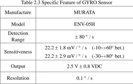
For lateral control, the steering system model is determined by an analysis of system response to step steering angle inputs. A gyroscope is used to measure the yaw rate response to the inputs. Proportional- derivative (PD) steering control gain values are then found by this experimental method. With regards to the sensor system, an ultrasonic sensor is used to detect obstacles for collision avoidance. A laser sensor and a hall effect sensor are used for the longitudinal control and an ultrasonic sensor is used for the lateral control. Further, an accelerometer and gyroscope are implemented to measure vehicle motion. The end result is that the multi-sensor interface system and sensor fusion system is very important to the unmanned vehicle control system and to the motion detecting system. Data coming from these sensors are used as input to the driving simulator. The driver riding on the simulator feels the motion generated by the vehicle motion generator, the so called driving simulator, which is based on the signal coming from unmanned vehicle motion monitoring system. At the same time, the driver sees the image data that comes from the unmanned vehicle. The driver controls the driver motion data acquisition system, which monitors the steering input, brake foot pedal input, and acceleration foot pedal input. All the data, including vehicle motion data, image data and vehicle control queue data, is transmitted by radio frequency communication, i.e. so called wireless communication.
In this thesis, the author presents the system modeling of the traction and the steering systems. In addition, sensor fusion based data acquisition and monitoring system evaluation is implemented. Further, the data transformation for the motion generation of the driving simulator and data acquisition for the motion control of the unmanned vehicle are defined.
Nomenclatures
βf : Side slip angle of front wheel βr : Side slip angle of rear wheel δ : Steering angle
τ : Torque of DC motor
ω : Rotational velocity of DC motor θ : Steering angle for PID controller A: Fixed frame
B: Moving link frame
en : Current error term in the system f : Friction constant of DC motor ia : Magnetic core current of DC motor if : Magnetic current of DC motor I : Yaw moment of vehicle J : Inertia of DC motor kd : Derivative gain
kf : Cornering force of front wheel ki : Integral gain
kp : Proportional gain
kr : Cornering force of rear wheel kt : Coefficient of DC motor
kv : Inverse electricity generation constant lf : Length from gravity center point to front lr : Length from gravity center point to rear La : Inductance component of magnetic windings m : Total mass of vehicle
AP: Position vector of the center of mass of a moving platform with respect to a fixed frame A
BP: Position vector of the center of a point P with respect to a fixed
frame A
ARB: 3×3 Rotation matrix that describes the orientation of frame B with respect to frame A
BRA: Inverse transformation of ARB , BRA= ARB-1
r : Yaw angular velocity Ra : Internal resistance
Yf1, Y f2 : Lateral force of each front wheel Yr1, Y r2 : Lateral force of each rear wheel u : Input voltage
va : Input voltage of DC motor
vk: Induced inverse generation of electricity
LIST OF FIGURES
Fig. 1.1 System configuration & Driving test --- 9
Fig. 1.2 Automated Guided Vehicle of Soong-Shil University --- 9
Fig. 1.3 KAV-5 System of Korea University --- 10
Fig. 1.4 Platooning Test of Hyundai Motor Company in proving ground --- 10
Fig. 1.5 Autonomous Vehicles of University of Florida (Mule)---16
Fig. 1.6 Autonomous Vehicles of University of Florida (AMRADS) ---16
Fig. 1.7 Navlab 5 by Carnegie Mellon University ---17
Fig. 1.8 The Sense-Plan-Act (SPA) paradigm ---24
Fig. 2.1 Concept of tele-operated vehicle system for a driving simulator ---25
Fig. 2.2 Block Diagram of Motion Control System --- 28
Fig. 2.3 DC Motor for Traction System ---30
Fig. 2.4 DC motor controller system --- 31
Fig. 2.5 Output Voltage VS Digital Input Value --- 33
Fig. 2.6 DC Motor Control Signal Flow --- 34
Fig. 2.7 Wire Model of Traction System --- 35
Fig. 2.8 Block Diagram of Traction System --- 38
Fig. 2.9 DC Motor RPM(Revolution Per Minute) Profile --- 38
Fig. 2.10 Simulation Result of Transfer Function --- 39
Fig. 2.11 DC Motor Hardware System for Brake --- 41
Fig. 2.12 2 Phase Step Motor System for Lateral Control --- 43
Fig. 2.13 Step motor pulses versus Steering angle --- 44
Fig. 2.14 Torque of Actuator via Input Pulses Per Second --- 45
Fig. 2.15 Characteristic Graph of Steering System (CW) --- 46
Fig. 2.16 Characteristic Graph of Steering System (CCW) --- 47
Fig. 2.17 Bicycle Model for Steering System Modeling --- 48
Fig. 2.18 Yaw Rate Profile by Gyro Sensor --- 52
Fig. 2.19 Simulation Result of Transfer Function --- 52
Fig. 2.20 Block Diagram of Sensor System --- 54
Fig. 2.21 System setup of Laser sensor --- 57
Fig. 2.22 Detective Range of Laser Sensor --- 57
Fig. 2.23 Ultrasonic sensor mounting --- 58
Fig. 2.24 Conic Detecting Field of Ultrasonic Sensor --- 59
Fig. 2.25 Position of ultrasonic & Laser Sensor --- 59
Fig. 2.26 Functional Diagram of Ultrasonic sensor --- 60
Fig. 2.27 Undetected Object due to reflection --- 64
Fig. 2.28 Range Error due to Angle between Object and Ultrasonic Sensor --- 64
Fig. 2.29 Histogram Grid for Obstacle Representation of Ultrasonic Sensor --- 66
Fig. 2.30 The Murata Gyrostar ENV-05H Gyroscope --- 71
Fig. 2.31 The Gyroscope Controller and Data Acquisition Module --- 72
Fig. 2.32 Rotate to Left Direction Test at Each Constant Velocity --- 73
Fig. 2.33 Rotate to Right Direction Test at Each Constant Velocity --- 73
Fig. 2.34 Position of Magnetic Hall Effect Sensor --- 74
Fig. 2.35 Position of Laser Scanner Sensor --- 75
Fig. 2.36 Laser Beam Resolution of the Laser Scanner Sensor --- 76
Fig. 2.37 Mapping of road with Laser Scanner --- 76
Fig. 2.38 Stewart Platform of 6 Degrees of Freedom --- 77
Fig. 2.39 Coordinate System of Stewart Platform --- 79
Fig. 2.40 Rotation angle & displacement of each axis --- 85
Fig. 2.41 Displacement of each axis by a platform moving --- 86
Fig. 3.1 The classification of compass error terms --- 90
Fig. 3.2 Angular locus of Unmanned Vehicle and Human Driving Test --- 91
Fig. 3.3 Proving Ground Road Profile (Corridor of Internal Building) --- 92
Fig. 3.4 Open Loop System Simulation with PID Controller --- 93
Fig. 3.5 Unmanned Vehicle Velocity Profile --- 94
Fig. 3.6 Deceleration Data of Unmanned Vehicle at 2.3[Km/h] --- 94
Fig. 3.7 Deceleration Data of Unmanned Vehicle at 12 [Km/h] --- 95
Fig. 3.8 Block Diagram of Closed Loop System --- 96
Fig. 3.9 Plant with PID Controller --- 98
Fig. 3.10 Plant without Controller --- 98
Fig. 3.11 Result of System Response with Controller --- 99
Fig. 3.12 Front Distance Range change ratio --- 100
Fig. 3.13 Laser Scanner Test Result (Front side 2m) --- 101
Fig. 3.14 Laser Scanner Test Result (Front side 3m) --- 101
Fig. 3.15 Locus of unmanned vehicle keeping the center of bilateral wall --- 103
Fig. 3.16 Map generation with Ultrasonic Sensor --- 103
Fig. 3.17 Locus of unmanned vehicle keeping the center of bilateral Wall --- 104
Fig. 3.18 Map generation with 4 Ultraonic Sensors --- 104
Fig. A.1 Estimating Current Position and Orientation of Unmanned Vehicle --- 110
Fig. B.1 DA-Interface Circuit --- 113
Fig. B.2 Driver for Brake Actuator --- 113
Fig. B.3 Data Acquisition and Display System of Laser sensor --- 114
Fig. B.4 A/D Interface board for Ultrasonic Sensors --- 114
Fig. B.5 Silk file of developed black-box PCB system --- 115
Fig. C.1 Lab-view Program Schematic for DAQ for DC Motor Control --- 116
Fig. C.2 Lab-view Program Schematic for DAQ for Step Motor Control --- 117
Fig. D.1 Collision Avoidance and Management Algorithm --- 118
LIST OF TABLES
Table 2.1 Traction System Specific feature --- 34
Table 2.2 Specific of Steering System --- 51
Table 2.3 Specific Feature of GYRO Sensor --- 53
Table 2.4 Specific Feature of Ultrasonic sensor --- 66
Table 2.5 The Mechanical Specification of Stewart Platform -- 78
Table 2.6 Maximum Working Space as a driving simulator ---- 84
Table 2.7 Minimum Working Space for continuous motion ---- 84
1 Introduction
1.1 Research Objectives & Background
Much research has been performed throughout the world in the area of unmanned vehicles and its associated social infrastructure.
Today, an autonomous vehicle can drive itself to a desired destination without a driver and without the aid of the social infrastructure. All that is needed are sensors and actuators. However, system stability is uncertain and the computational cost of semi-autonomous systems is high, i.e. it requires expensive hardware systems, real time monitoring techniques, and multiple control techniques. Therefore electronic control research is very important for this type of effort. The benefits of this research are increased driver convenience and reduced driver fatigue and stress experienced during long driving times. In addition, every country has a serious problem with traffic and road efficiency because of the large increase in vehicle ownership. Currently, however, the most frequent vehicle research isn’t focused on engine development for power performance or chassis improvement for riding comfort, but on the driving stability and fuel consumption for air pollution.
The key elements of an unmanned vehicle are a reliable actuator system and sensor system that has precision and sensitivity.
However, the overall reliability of unmanned vehicle driving is low and it requires many road tests and much sub system development.
Therefore reliable and sensitive sensors, like the micro millimeter wave laser sensor or laser scan sensor that have precise measurement ability and durability, are very important for the automation of an unmanned vehicle. It must be pointed out that there is a general lack of information in the published literature that makes it difficult to compare the merits of various types of unmanned vehicles. A typical reference paper would contain only simulation results, and in general the assumptions used in updating the vehicle’s position and direction are not specified.
In this thesis, a technique for sensor fusion is presented together with actuator control for the design of the unmanned vehicle.
Further the inverse and forward kinematic analysis of the Stewart platform, which is coupled with unmanned vehicle, for high realistic driving simulator is presented.
The main theme of this paper is the system design &
integration, generating the unmanned vehicle's motion and development of basic technical elements. This research is summarized in the following sections.
1. Unmanned Vehicle Part
An unmanned vehicle should be autonomous and the system should be stable. This can be achieved via a sensor fusion actuator control technique that integrates an accelerometer, gyro sensor, hall magnetic sensor, and laser sensor with actuators such as a DC servo motor, AC servo motor, and stepper motor. This is accomplished in this research [Kor93].
2. Driving Simulator Part
The driving simulator used in this investigation is the Stewart Platform type with 6 actuators. These actuators control the position, velocity, and acceleration of the upper platform. The position, velocity, and acceleration of the top platform are based on information sensed at the vehicle, i.e. the vehicle’s position, velocity, and acceleration. The algorithm accounts for the limited workspace of the driving simulator platform, for the discreet data input, and for the delay associated with communication of the sensed data from the vehicle to the driving simulator.
3. System Integration Part
Sensor data from the unmanned vehicle is transmitted to the driving simulator, which generates the command motion of the simulator platform. The driver riding on the simulator feels the motion of vehicle, watches the image data, synchronously, and defines the situation of the vehicle and controls the driver motion generator in the cockpit. The vehicle control queue that comes from the driver motion generator is transmitted to the unmanned vehicle, so the vehicle is controlled by the driver. In this research, the feasibility of unmanned vehicle system design, coupled with the driving simulator, and integration of these two systems is fulfilled.
It may be the case that the cost and time for development of new car might be diminished through the integration of an unmanned vehicle (or a modeled vehicle) and driving simulator. In addition, the system can be applied to exploration of unknown rough terrain and economical benefits resulted from grafting with ITS are expected.
1.2 Importance of Research
This research would be of benefit to the autonomous land vehicles used for surveying, exploring rough terrain, or plowing large and relatively flat plots of land where 100% coverage is desired. In addition, the importance of this research is classified into three parts as follows:
1. Technical View: A conventional vehicle is concerned only with the method of mobility and the comfort, safety, and convenience for the occupants. In addition, this investigation focuses on the development of the system to automate boring, monotonous tasks and to operate in dangerous environments.
2. Economical & Industrial View: The growing number of older drivers, the total number of vehicles, and confined road space result in traffic accidents. This represents a serious economic loss. Because of this, several developed countries perform research related to the social infrastructure and to unmanned vehicles. Vehicle automation can reduce the frequency and severity of traffic accidents via application of technologies
such as collision avoidance systems. In addition, the cost of new vehicle development is very expensive because the vehicle must have many ground tests for safety verification. With a driving simulator interfaced with real or simulated vehicles, vehicle design parameters can be easily changed in software.
Modifying these variables and testing on a simulated or virtual ground, make it possible to reveal the trend of vehicle suspension and engine performance characteristics, at low cost.
3. Social and Cultural View: All of the research performed by developed countries on unmanned vehicles and social infrastructure are characterized to that country’s particular environment. Korea, with many mountain and twisted roads, cannot be conformed to by imported systems due to serious problems associated with system maintenance and management. The end result is that the system should be accepted by domestic road conditions while diminishing cultural discrepancy. In human factor studies, the human sensibility ergonomic technology concerns measuring and indexing human sensibility qualitatively and quantitatively, and
applying the indexed database to design of products and environments that will lead to more convenient, more comfortable and safer human life. In developing the technology, a test-bed capable of creating physically meaningful situations in a safe and tightly controlled environment can become a useful research tool for various sensibility ergonomics studies.
1.3 Previous Research Trend of the World
Today, vehicle development has been focused on increased performance and function with safety in mind. These factors are considered more and more as key elements of vehicle development.
The research on vehicle safety in America, Europe, and Japan appears to focus on active safety elements. As a result of this trend, the collision avoidance system has advanced. This system makes it possible to escape from colliding with obstacles by issuing warning sounds and even brakes the vehicle. Domestic and international research trends are presented as follows:
1.3.1 Domestic Trend
In the early nineties [Kor 93], domestic research at academia and Government was supported by the G7 project about Neo Advanced Vehicle Technique Development. The research on unmanned vehicles was divided into work on the vehicle itself and on the infrastructure.
The vehicle related research focused on autonomous management techniques and tele-operation techniques. Sensor fusion techniques to integrate sensed data to perform longitudinal and lateral motion control was coupled with ITS(Intelligent Transportation System) and platooning was successfully demonstrated as shown in Figure 1.1.
Fig. 1.1 System configuration & Driving Test
Fig. 1.2 Automated Guided Vehicle of Soong-Shil University
Fig. 1.3 KAV-5 System of Korea University
Fig. 1.4 Platooning Test of Hyundai Motor Company in proving ground
The unmanned vehicles developed in Korea are classified as Autonomous Vehicle, Mobile Robot, Auto-Surveying Vehicle, etc.
Each system is almost same with regards to the concept and basic hardware, however, the application and detailed propulsion system and sensor system differ. Figures 1.2, 1.3 and 1.4 show the successful results in the area of unmanned vehicle and ITS related system in Korea [Jan99].
1.3.2 International Trend
The development trend of unmanned vehicles in the world is led by several countries. The U.S.A., Japan, and European Union have been investigating advanced automated vehicles since the 1980s.
Advanced vehicle control techniques in the United States are on the vanguard, and there is a long history related to this topic. The beginning of this research was the PATH Project in the middle of the 1980s and the cornerstone of it is a demonstration of platooning in San Diego, which has 7.6 miles long Automated Highway System interfaced with several buses and passenger cars. An autonomous vehicle developed at Carnegie Mellon University has crossed the American continent. The vehicle had a vision system, navigation system, and laser rangefinder and was developed in the middle of the 1990s. In addition, they developed the system algorithm for safe driving and collision avoidance and implemented a method for arriving at a destination via path planning.
Caltech has completed a path tracking system, mapping system for unknown environments, detection algorithm, and a sensor fusion system for mobile robots. They demonstrated a Real-Time Communication Autonomous Robot System, unmanned shuttle bus,
and an unmanned vehicle system for military purposes.
The University of Florida has developed several unmanned vehicle systems. The Navigation Test Vehicle is based on a Kawasaki Mule vehicle that has been automated via the integration of hardware and control software. Path planning software determines a collision free path to a goal location. Vehicle control software then works with obstacle detection sensors and software to control the vehicle along the path. The first implementation of the vehicle consisted of a VME based computer system running the VxWorks operating system. Multiple processors were integrated on a single backplane using shared memory to transmit data between processes. The current implementation involves the integration of specific components running on multiple computer nodes. The implemented computer architecture was developed as a precursor to the U.S. Department of Defense Joint Architecture for Unmanned Ground Systems (JAUGS).
In the area of driving simulators the research trend comes from primitive forms that were developed in the 1970s. Advanced flight simulators were then developed in the early 1990s. With the advent of computer technologies, Daimler-Benz in Germany launched a high fidelity driving simulator in the early 1980s, which created wide
interest throughout the world. Since then, many automotive makers and research institutions have developed and applied their own simulators that meet application purposes and target performance. As an example, the construction of the state-of-the-art National Advanced Driving Simulator(NADS) was undertaken in the United States in 1990.
1.3.3 System Analysis of successful Cases 1.3.3.1 University of Florida
The University of Florida (UF) has considerable experience in the design and development of Automatic Navigation Vehicle Systems over the past ten years. The research topics at UF are path planning, obstacle detection, vehicle control, positioning system development, and vehicle architecture. The University of Florida research in the area of autonomous vehicle systems is supported by the Air Force Research Laboratory at Tyndall Air Force Base, Florida. The sub-research topics of the Center for Intelligent Machines and Robotics (CIMAR) of UF are classified by 4 areas as follows: [Cra 95].
1.1 Path Planning: CIMAR developed three types of off-line path planning algorithms. The first algorithm determines a minimum
distance path from a starting position and orientation to a goal position and orientation taking into account known obstacles and vehicle motion parameters such as size and minimum turning radius. The second algorithm determines an efficient survey path for a given area with known obstacles for cases where autonomous surveys are to be performed. The third algorithm determines a survey path where the terrain is accounted for such that the vehicle will not traverse slopes that exceed the allowable vehicle capability.
1.2 Obstacle Detection and Mapping: CIMAR uses sensors for detecting an unknown obstacle with ultrasonic sensors and a laser range finder by a sensor fusion technique. Researchers of CIMAR place a hypothetical grid around the working area of the unmanned vehicle. Each grid cell has a numerical value, which corresponds to the probability of occupancy. A value of 0 means that a cell is empty, a value of 1 corresponds to a 100%
chance of occupancy, and a value of 0.5 corresponds to unknown. Occupied grid cells and empty grid cells are encapsulated by polygons when the vehicle (and grid) translates away from the cell location.
1.3 Vehicle Control: CIMAR uses a control technique that causes the vehicle to follow a prescribed path. The control technique is based on the Screw Theory. The Screw Theory explains that instantaneous motion can be described as a rotation about a line in space with an associated pitch. The Screw Theory is applied to minimize the position error and orientation error, causing the vehicle control to remain stable. This control technique has allowed the vehicle to remain stable when following a path at increased velocities. The control algorithm has been tested up to the maximum vehicle velocity of 13 miles per hour.
1.4 Positioning System: CIMAR developed an Inertial Navigation System (INS) coupled with a Differential Global Positioning System (DGPS) via a Kalman filter as a Positioning System.
The INS generates the information of the vehicle position and orientation even if the DGPS is not able to get data from the satellites because of obstructing objects such as trees or tall buildings.
Fig. 1.5 Autonomous Vehicles of University of Florida (Mule)
Fig. 1.6 Autonomous Vehicles of University of Florida (AMRADS)
1.3.3.2 Carnegie Mellon University
Carnegie Mellon University (CMU) researched Machine Vision, Navigation System, Path Tracking System and the Sensor Fusion System from the 1990’s. An impressive work in the area of explicit path tracking for autonomous vehicles was fulfilled by Shin and his colleagues of the NavLab [Sin 91].
Fig 1.7 Navlab 5 by Carnegie Mellon Univsity
Under the FastNav project, semi-autonomous navigation was accomplished over the interstate highway in America at 11[m/s], using
a modified van. It has four main subsystems, such as path tracking, obstacle detection, obstacle avoidance, and a real-time computing architecture. They developed the algorithm for stable driving by anticipating the obstacle and car crash point of the road and by performing vehicle dynamic modeling for path planning through a simulation [Sin 91]. The researchers in the NavLab tested several path tracking algorithms, such as pure pursuit, a polynomial fit method, and a control theory approach. They used motion controller modules, which are a mapper, a tracker, and a velocity regulator. Figure 1.7 shows the unmanned vehicle system of CMU.
1.3.4 Review of the Literature
Unmanned vehicles pose an enthusiastic challenge to artificial intelligence and control researchers all over the world. Unmanned vehicles are autonomous systems and the researcher must develop a control approach that endeavors to deal with the uncertainty of sensing and actuating, reliability, and real time response. Unmanned vehicles also require the integration of sensing, acting, and planning within a single system. These are all hard problems, but ones that must be solved. Many researchers have been working on these problems and have published many invaluable papers.
Unmanned vehicles are sometimes classified as a branch of mobile robots. The definition of a mobile robot is a robot that has mobility in the sense that it is not stuck down to the ground or to another surface without other help. In the classical definition of robot, robots were industrial tools used for pick and place maneuvers, welding, painting, and assembly. Further, mobile robots can be classified on the basis of the space where they work, such as indoors or outdoors and in industry or at home.
1.3.4.1 Sorts of Unmanned Vehicle
Unmanned vehicles can be categorized into three types according its method of control and where it works, i.e. autonomous guided vehicles (AGVs), autonomous land vehicles (ALVs) and automated highway vehicles (AHVs). AGVs, mostly have two wheels, have been successfully used in factories for over ten years, delivering material or people to designated places. AGVs usually follow the lines on floors, buried magnetic wires or permanent magnets located sparsely with special configurations conformed to working spaces.
Dead reckoning (D.R.) is used to calculate an AGV’s current position and orientation, but error comes from wheel slippage, causing malfunction of positioning. ALVs are designed to navigate on unknown ground and rough terrain and to perform exploration. Researchers in the area of ALVs are interested in image processing, object recognition, path planning, and obstacle avoidance.
Artificial intelligence techniques are often applied to improve image quality and computational performance of the processors.
Vehicle dynamics do not play an important role in vehicle control for ALVs because the vehicle’s speed is very low. However, for dead reckoning navigation, vehicle statics are considered as a control term.
The control of car-like ALVs is a popular research field, because wheeled ALVs are energy efficient, structurally simple, and there is a wealth of technical information available from the automotive industries in cases where it is to be mass-produced [Sim91].
Regarding AHVs, highway automation is currently under study as a remedy to recurring traffic congestion and frequent accidents that account for thousand of deaths and injuries all over the world. Every year, nearly a million people die in car accidents on highways. It is anticipated that the increase in the number of vehicles operated in the world will pose a heavy strain on the road capacity and safety of the present highway system. Automated highways may be a partial solution to improving highway safety and capacity. This research topic is combined with two areas of automatic vehicle control and traffic control strategy, which is embodied in intelligent transportation systems.
ITS have a very wide range of research areas and it is more and more coupled with unmanned vehicle systems. The spreading out of autonomous vehicles on highways is considered a part of the Advanced Vehicle Control System (AVCS) and the Intelligent Vehicle Highway Systems (IVHS). It is expected that the number of car accidents on the road can be diminished by eliminating human operation error, such as
dozing driving, drunken driving, and careless driving.
AHVs are controlled using two independent control strategies, one is lateral control and another is longitudinal control, which means the control of steering angle and velocity.
1.3.4.2 Autonomous Vehicle Control Architectures
There are many applied control theories for vehicle motion.
Vehicle control means the control of vehicle motion so as to guide the vehicle to a desired position. However, the control of a vehicle is not always predictable, because there are many disturbances and unknown factors. Typically, researchers consider the tire model, chassis model, and even the engine power train. John [Joh 94] researched vehicle tires and steering control, and his book is regarded as the most respected textbook on this topic. John describes the mechanism and dynamic of steering systems, coupled with the tire model. He explains that a basic vehicle is considered to be one which uses the variables of vehicle velocity, lateral velocity, and yawing velocity to describe the behavior resulting from disturbances due to steering, acceleration, braking, and side wind. However, in the areas of unmanned vehicle control, the velocity of the vehicle is slow, almost below 20[km/h], which means
that because of the low speed, unmanned vehicles does not have severe acceleration and can be considered as static, so the dynamics of the vehicle can be neglected.
An unmanned vehicle’s position and orientation, which utilizes a steering mechanism and Ackerman linkage, is represented by three parameters (x, y, θ). It means that an unmanned vehicle, which has a steering mechanism, has a turning radius while it makes a J-turn.
Such systems are referred to as nonholonomic but systems which do not have a minimum turning radius, such as two wheeled vehicles, are called holonomic systems.
The parameters x and y represents the position of the unmanned vehicle and θ corresponds to orientation, or the heading angle. However, for unmanned vehicle control, there are two degrees of control, i.e. lateral control and longitudinal control. The Ackerman mechanism in steering unmanned vehicle are nonholonomic because their constraint equation is not to be integrated. The motion of a nonholonomic unmanned vehicle is constrained by the Eq. 1.1,
0 cos
sin + =
−
θ
dxθ
dy (1.1)where θ is the current orientation of the unmanned vehicle and (dx, dy) are incremental displacements in position. A nonholonomic equality
constraint is a nonintegratable equation involving the configuration parameters and their derivatives. Nonintegratable system means the analysis of their kinematics, dynamics, and motion control is difficult.
The key point is that the analysis of unmanned vehicles has many of the same elements as the analysis of manipulator kinematics.
Differential displacements of the wheel’s location and steering angle are used to determine the current pose of the vehicle. This is referred to as estimation of position, which is described in detail in Appendix A.
Murphy[Mur 94] describes the control of unmanned vehicle as solved with a sensing method. The world model is interpreted along with the sensor data such that a plan can be generated. Each step of the plan was then executed using the mobile robot control system. In the classical control method, sense-plan-act (SPA) is a main strategy, however, as the number of unmanned vehicle sensors increases, the SPA cycle could not follow the state of the robot’s desired performance.
He solved this through a new sensor fusion method [Mur 97].
Fig. 1.8 The Sense-Plan-Act (SPA) paradigm
Sensing World Model Planning Control Execution
2 Hardware System Configuration
This chapter describes the hardware system of the unmanned vehicle developed by the author to navigate over unknown outdoors terrain or in indoors environments such as corridors. The objective of the effort is to make the system easier to operate and low cost for the particular application.
Fig. 2.1 Concept of tele-operated vehicle system for a driving simulator
This research is focused on the system design and development of a reliable unmanned vehicle, with emphasis placed on multi sensor fusion, characteristic analysis, modeling of the vehicle, controller design, and parameter tuning for performance improvement. Fig. 2.1 shows the overall concept of the research and the data flow for the
S e n s o r F u s io n V e h ic le C o n tr o l
U ltr a S o n ic S e n s o r
L a s e r S e n s o r S c a n n e r C C D
U n m a n n e d V e h ic le
V e h ic le S y s te m
W ire le s s M o d e m
W ire le s s M o d e m
M o tio n B a s e E n c o d e r
A C S e rv o D riv e r A C S e rv o C o n tro lle r
A C S e rv o M o to r
C C D C a m e ra
Im a g e D a ta A c c e le ra tio n
c o n tro l B ra k e c o n tro l G y ro
S e n s o r
S te e rin g c o n tro l S o n ic
S e n s o r
Im a g e D a ta
M o tio n C o n tr o lle r
S im u la to r S y s te m V e h ic le
C o n tro l Q u e u e P o s itio n
V e lo c ity A c c e le r a tio n T u rn in g A n g le
D r iv e M o tio n G e n e r a t o r
2 C o n tro l s y s te m M o tio n 1
V e h ic le M o n ito rin g S y s te m
.
l
..
l H a ll
S e n s o r L a s e r S e n s o r
A c c . S e n s o r
L a te ra l C o n tro l L a te r a l M o n ito r in g
L o n g itu d in a l M o n ito rin g L o n g itu d in a l C o n tr o l
A c c . P e d a l P o s . B r a k e P e d a l P o s . H a n d le A n g leθ θ. θ..
l S e n s o r F u s io n V e h ic le C o n tr o l
U ltr a S o n ic S e n s o r U ltr a S o n ic S e n s o r
L a s e r S e n s o r S c a n n e r L a s e r S e n s o r S c a n n e r
C C D C C D U n m a n n e d V e h ic le
V e h ic le S y s te m
W ire le s s M o d e m
W ire le s s M o d e m
M o tio n B a s e E n c o d e r
A C S e rv o D riv e r A C S e rv o C o n tro lle r
A C S e rv o M o to r
C C D C a m e ra
Im a g e D a ta C C D C a m e ra
Im a g e D a ta A c c e le ra tio n
c o n tro l B ra k e c o n tro l A c c e le ra tio n
c o n tro l B ra k e c o n tro l G y ro
S e n s o r
S te e rin g c o n tro l S o n ic
S e n s o r
Im a g e D a ta Im a g e
D a ta
M o tio n C o n tr o lle r
S im u la to r S y s te m V e h ic le
C o n tro l Q u e u e P o s itio n
V e lo c ity A c c e le r a tio n T u rn in g A n g le
D r iv e M o tio n G e n e r a t o r
2 C o n tro l s y s te m M o tio n 1
V e h ic le M o n ito rin g S y s te m
.
l
..
l H a ll
S e n s o r L a s e r S e n s o r
A c c . S e n s o r
L a te ra l C o n tro l L a te r a l M o n ito r in g
L o n g itu d in a l M o n ito rin g L o n g itu d in a l C o n tr o l
A c c . P e d a l P o s . B r a k e P e d a l P o s . H a n d le A n g leθ θ. θ..
l
interaction of the unmanned vehicle with the driving simulator. The data, i.e. acceleration, velocity, position, orientation, heading angle and environment information coming from sensors onboard the unmanned vehicle are evaluated and transmitted to the driving simulator via a wireless modem. These data are then converted to the length, velocity and acceleration of each actuator of the driving simulator to simulate the unmanned vehicle’s motion. In addition to this fact, the driver who is riding on the driving simulator sees the image data coming from a CCD camera mounted on the unmanned vehicle and the driver controls the driving motion generator, handle angle, acceleration pedal, and brake pedal position of the simulator cockpit, inputting data into the vehicle control queue. The vehicle control queue data is transmitted to the unmanned vehicle again making a closed loop system.
2.1 Control System
The concept of longitudinal and lateral control is very important for the first step of the unmanned vehicle design.
Longitudinal control for an unmanned vehicles envisions automatic controlled platoons of vehicles, each containing sensors, actuators and communication equipment. The goal of longitudinal control is to decrease the required inter vehicle spacing for a platoon of vehicles traveling at high speeds. These methods usually develop control laws for each vehicle in the platoon using the lead vehicle’s velocity and acceleration, the preceding vehicle’s velocity and acceleration and the distance between the vehicle and the preceding vehicle. Lateral control for an unmanned vehicles involves developing steering control laws capable of keeping an automated vehicle inside a perceived lane.
Furthermore, there are two control methods for velocity control. One is the linear position control of the acceleration pedal or throttle valve, which means that it requires another actuator for controlling the pedal position. The other is the direct command signal control of the DC motor input signals in the case that the unmanned vehicle’s traction system is via electrical propulsion. The former is easy to drive and monitor but it is hard to control because of the position error of the
actuation mechanism. The later is easy to control because the signal is generated by preparatory control algorithms, such as path planning. The vehicle velocity is calculated from monitoring the rotating wheel, which is accomplished by counting a rising signal edge at each sampling time. It is stored as velocity data per time unit, generally at a rate of 10 Hz, and displayed. On the basis of this data, the total driving distance and velocity is calculated and the velocity profile of the vehicle locus is generated for path planning.
Wireless Modem Sending Vehicle Control Queue Generation
PC
Driving Simulator
Encoder
AD Converter
Brake Pedal Handle
Acceleration Pedal
Volum e Resistance Volume Resistance
AD Converter Encoder
Controller
Wireless Modem Receiving Vehicle Motion
Control PC Acceleration
System
Brake Actuator Handle
Actuator
OP AMP DC Motor Controller
DAC 0800
DC Motor Relay
Relay Controller PCL-7122 Step Motor
Driver Step Motor
PK296
PCL-839 Unmanned Vehicle
Acceleration queue
Braking queue Steering
queue
Handle Angle
Acceleration Pedal Position Brake Pedal Position Wireless
Modem Sending Vehicle Control Queue Generation
PC
Driving Simulator
Encoder
AD Converter
Brake Pedal Handle
Acceleration Pedal
Volum e Resistance Volume Resistance
AD Converter Encoder
Controller
Wireless Modem Receiving Vehicle Motion
Control PC Acceleration
System
Brake Actuator Handle
Actuator
OP AMP DC Motor Controller
DAC 0800
DC Motor Relay
Relay Controller PCL-7122 Step Motor
Driver Step Motor
PK296
PCL-839 Unmanned Vehicle
Acceleration queue
Braking queue Steering
queue
Handle Angle
Acceleration Pedal Position Brake Pedal Position
Fig. 2.2 Block Diagram of Motion Control System
Fig. 2.2 illustrates the flow of Fig. 2.1, which represents the main theme of this research. The operator rides on the driving simulator
and provides input to the system such as the acceleration pedal position input and brake pedal position input. The voltage variation of variable resistance is converted to a digital signal. The steering input signal is generated from an encoder because the steering input is rotational angular measurement that requires rotational position and direction information.
The hardware system of the unmanned vehicle is controlled by an I/O card that controls each actuator. This card is interfaced with the vehicle motion control PC. The steering system uses a 2 phase stepper motor and is controlled by a PCL-839 Add-On Card. The encoder signal processing is controlled by a PCL-833 Add-On Card, but it is not shown in Fig. 2.2. For safety and maintenance while the unmanned vehicle is driving, the following requirements must be met:
[1] The vehicle should maintain a desired velocity.
[2] The vehicle should maintain a safe distance from the preceding vehicle and avoid any obstacle in front of the vehicle that may appear abruptly.
[3] The vehicle should have a comfortable ride, which comes from the limitation of acceleration.
2.1.1 Longitudinal Control
In this research, the unmanned vehicle is an electric vehicle that has a brushless DC motor. The most obvious advantage of the brushless DC motor is the removal of the brushes. Brush maintenance is no longer required and problems associated with brushes are eliminated. These motors have a high torque/inertia ratio. They can be used in hazardous environments or even under-water applications.
The motor driving system controls the input voltage to the motor by digital signal processing, and conversion to an analog signal via a D/A converter.
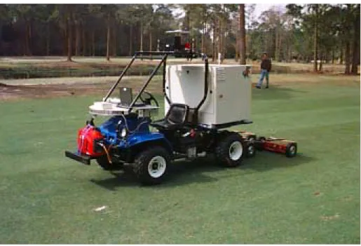
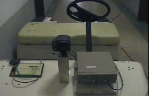
Fig. 2.3 DC Motor for Traction System
In this research, the vehicle for the experiment is an electronic vehicle like a utility car, which can be seen on golfing ground or in an airport. Fig. 2.3 shows the traction system of the unmanned vehicle.
The vehicle’s velocity is calculated from the rotating wheel, which is accomplished by counting a rising signal edge per unit time. It is stored as velocity data and displayed. On the basis of this data, the total driving distance is calculated and the velocity profile of vehicle locus is generated for path planning.
Fig. 2.4 DC motor controller system
Fig. 2.4 shows the DC Motor controller system for the drive actuator wired with the DC Motor. This controller gives a voltage signal to the motor, so it generates the torque, which causes the wheel to rotate.The displacement control of the vehicle means wheel angle control, so the velocity can be calculated from the number of wheel rotations per unit time.
The traction system of the unmanned vehicle has a DC motor, which requires 2.2 Kw of power at a voltage level of 48 volts. The motor drives a 2:1 gear ratio transaxle. Before the vehicle was modified for this research, it had an acceleration pedal driven system, which is operated by the position of pedal by the driver, generating the voltage signal for the controller. The input signal from the driver while they operate the pedal changes the Pulse Width Modulation (PWM) duty ratio and it controls the velocity of the vehicle. The author designed the D/A converter (DAC0800) interface board and accomplished the digital control of the traction system by use of a PCL7122 I/O Interface Add- On Card. This makes it possible to control the vehicle with a preliminary digital signal such as produced by a path following algorithm through subdividing the TTL Level into 256 combinations, which means 8 [bits]. The 8 [bits] digital value of the desired velocity is
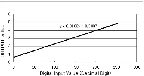
converted to an analog current by a D/A converter and inputted to the motor driver as a proportional voltage through an OP-AMP (LF 356N), which is a current-voltage conversion circuit. The schematic drawing is shown in Appendix B, Fig. B.1. Fig. 2.5 shows that the proportional relation, output voltage of OP-AMP and input digital value (256 times iteration) of the preliminary program.
Table 2.1 show that the specific features of the unmanned vehicle traction system. The unmanned vehicle has 6 batteries connected directly with each battery having a potential of 8 volts, which provides a total potential of 48 volts. Fig. 2.6 shows the signal flow of DC motor control and command data conversion.
Fig. 2.5 Output Voltage VS Digital Input Value
Table 2.1 Traction System Specific Feature
Fig. 2.6 DC Motor Control Signal Flow
Motor Type DC Motor
Generating Power 2.2kw/3hp – 2,800rpm
Input Volt DC 48V
Maximum Input Amp DC 32AMP
Transaxle Double Reduction Helical Gear Battery 48 Volt/8V×6ea, 165AH
2.1.1.1 Traction System Modeling
In this research, the traction system model is set up as shown in Fig. 2.7. This equivalent circuit model allows for more precise control and performance improvement [Par98].
ω )
(t
u R
cR
a) ( t
i
ai
f) ( t
v
aL o a d
= c o n s ta n t
+ -
n = 1 /2
L
a+ -
) k(t
v
ω )
(t
u R
cR
a) ( t
i
ai
f) ( t
v
aL o a d J, f
= c o n s ta n t
+ -
n = 1 /2
L
a+ -
) k(t
v
ω )
(t u (t )
u R R
ccR
aaR
) ( t
i
aa( t)i
i
ffi
) ( t
v
aa( t)v
L o a d
= c o n s ta n t
+ -
n = 1 /2
L
aaL
+ -
) k(t
v
k(t)v
ω )
(t u (t )
u R R
ccR
aaR
) ( t
i
aa( t)i
i
ffi
) ( t
v
aa( t)v
L o a d J, f
= c o n s ta n t
+ -
n = 1 /2
L
a+ -
) k(t
v
L
aaL
+ -
) k(t
v
k(t)v
Fig. 2.7 Wire Model of Traction System
The input voltage of the motor, va(t) is controlled by proportionally to the input voltage u(t) of the circuit, where ia(t) is the magnetic core current, Ra is the internal resistance, La is the inductance component of the magnetic windings, and vk(t) is an induced inverse generation of electricity while the motor is rotating. The torque τ can be written as in Eq. 2.1 where J is the inertia of the motor, f is the friction constant of the motor, and kt is the torque constant.
ω ω
τ
fdt J d i
kt a = +
=
(2.1)
In the magnetic voltage control theory, the core current and magnetic current if is held constant and torque is proportional to this current. If the magnetic field rotates, the voltage proportional to magnetic flux by acceleration is induced. Thus the induced voltage vk(t) is proportional to acceleration as
v
ω
k t k
v ( )=
. (2.2)
where, kv is the inverse electricity generation constant. The voltage equation of the equivalent circuit Fig. 2.7 can now be written as follows:
u(t)=kava(t)
(2.3)
dt L di i R t v t
va( )− k( ) = a a + a a
(2.4)
The DC motor mathematical model based on the magnetic voltage control theory can be written as follows:
) ( )
(t k v t
u = a a (2.5)
dt L di i R t v t
va( )− k( )= a a + a a (2.6)
vk(t)=kvω (2.7)
ω ω
τ
fdt J d i
kt a = +
= (2.8)
If it is assumed that all initial conditions are 0 and Ra and kv are constant, the Laplace transform equation can be written as follows:
U(s)=kaVa(s)
(2.9) )
( ) (
) ( )
(s V s R L s I s Va − k = a + a a
(2.10)
Vk(s)= kvΩ(s)
(2.11) )
( ) (
)
(s Js f s I
kt a = + Ω
τ
=(2.12) The equation can now be written with input U(s) versus output Ω(s) as follows:
v t a a
a a
t a
k k f R s f L J R Js L
k k s
U s
+ +
+
= + Ω
) (
) (
) (
2
(2.13)
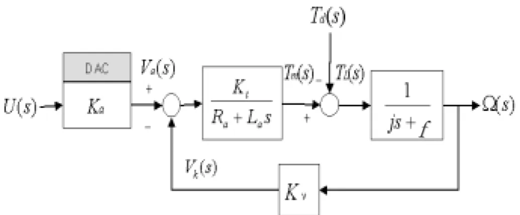
Fig. 2.8 shows the system block diagram of transfer function of Eq. 2.13.
Fig. 2.8 Block Diagram of Traction System
Exact values for the motor inertia, internal resistance, and inductance values are difficult to determine. They can be determined from iterative experiments as an approximate value, making the transfer function completely known [Fra95].
5 7 5 7 . 5 5 8 5 8 . 5 5 9 5 9 . 5 6 0 6 0 . 5 6 1 6 1 . 5 6 2
- 5 0 0 0 5 0 0 1 0 0 0 1 5 0 0 2 0 0 0 2 5 0 0 3 0 0 0 3 5 0 0 4 0 0 0
t i m e
rpm
Fig. 2.9 DC Motor RPM (Revolution Per Minute) Profile
f f
Fig. 2.9 shows the velocity profile data after a step input is applied to the motor. Based on this result, the natural frequency and damping ratio can be found. The transfer function can be written as Eq.
2.14.
111 . 7 55 . 4
575 . 5866 )
( ) ) (
( 2
+
= +
= Ω
s s
s U s s G
(2.14)
This experiment was performed using the LabView software.
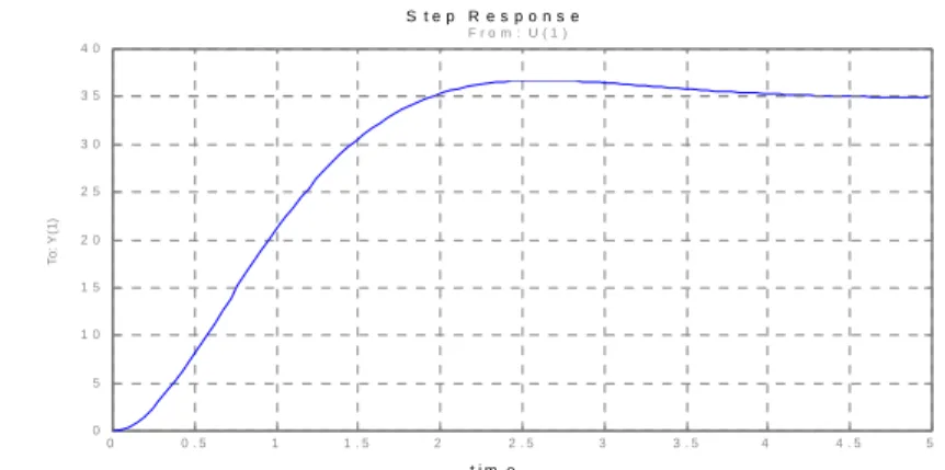
The program schematic file view is shown in Fig. C.1 of Appendix C [Lis 95]. To verify the transfer function Eq. 2.14, it is simulated with the MatlabR program. Fig. 2.10 shows the simulation result of the transfer function, Eq. 2.14.
t i m e
motor rpm
p l a n t
0 0 . 5 1 1 . 5 2 2 . 5
0 5 0 0 1 0 0 0 1 5 0 0 2 0 0 0 2 5 0 0 3 0 0 0 3 5 0 0
F r o m : U ( 1 )
To: Y(1)
Fig. 2.10 Simulation Result of Transfer Function
2.1.1.2 Brake Control System
Some researchers have attempted to control DC motors with a variable resistor or variable resistor connected to a transistor. While the latter approach works well, it generates heat and hence wastes power.
The simple PWM DC motor control eliminates these problems. It controls the motor speed by driving the motor with short pulses.
These pulses vary in duration to change the speed of the motor. The longer the pulses, the faster the motor turns, and vice versa.
The basic notion of brake control is the master cylinder control linked with a brake pedal of a passenger car. The author, however, has chosen to use a DC motor as the main actuator of the brake control system on the test vehicle, indirectly. To control vehicle velocity and acceleration and to stop the vehicle, the control of the braking system is required. The brake system is shown in Fig. 2.11, which shows the DC motor attached on the bottom side of the vehicle floor and geared directly to the brake pedal. The reaction force of the brake pedal is estimated by a torque meter at 40[kg∙f], and a 100:1 gear ratio is attached to a motor axis for safety. The DC motor power requirement is 200[W]. The interface and H-Bridge circuit for direction control is shown in Fig. B.2 of Appendix B.


![Fig. 2.24 Conic Detecting Field of Ultrasonic Sensor F R O N T R E A RL E F T S I D E R I G H T S I D EL a s e r S e n s o rU lt r a s S o n ic S e n s o r1 0 - 1 0 0 [ m ]1 4 °1 4 °1 4 ° 1 4 °1 4 °1 4 °1 4 ° F R O N TR E A RL E F T S I D E R](https://thumb-ap.123doks.com/thumbv2/123dokinfo/5257169.136810/71.774.222.557.171.465/fig-conic-detecting-field-ultrasonic-sensor-el-rl.webp)
