< 논 문 or 기 술 논 문 택일 >
A Study on Temperature Field of Solid Disc Brake based on Thermal- mechanical Coupled Model
Xuan Wu†, Pyung Hwang*, YoungBae Jeon**
열 -기계적 복 합 모 델을 기반으 로 한 Solid 디스 크 브 레이크 의 온 도 장에 관한 연구
우 쉔
†· 황 평
*· 전영배
**Key Words : Thermal-mechanical coupling, temperature field, brake disc, single stop brake, FEM
Abstract
The disc-pad brake system is an important part of automobile safety system. During braking, the kinetic energy and potential energies of a moving vehicle are converted into the thermal energy through frictional heat between the brake disc and the pads. Most of the thermal energy dissipated through the brake disc. The temperature could be exceed the critical value for a given material, which leads to undesirable effects, such as the brake fade, premature wear, brake fluid vaporization, bearing failure, thermal cracks, and thermally- excited vibration. The object of the present study is to investigate temperature field and temperature variation of brake disc and pad during single brake. The brake disc is decelerated at the initial speed with constant acceleration, until the disc comes to stop. The pad-disc brake assembly is built by 3D model with the appropriate boundary condition. In the simulation process, the mechanical loads are applied to the thermo- mechanical coupling analysis in order to simulate the process of heat produced by friction.
1. Introduction
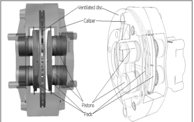
As an important part of automobile safety system, the brake system plays an important role in the protecting the driver and passengers. Disc brakes are widely used for reducing velocity due to their characteristics of braking stability, controllability and ability to prove a wide- ranging brake torque. The disc-pad brake consists of two parts: a rotating disc, and stationary pads [Fig. 1].
The braking processes in the friction units of a brake are very complicated. In the cause of braking, 95% of
mechanical energy is transformed into heat. The remaining 5% is dissipated through noise, light, gaseous emissions, ets. Most of heat energy is dissipated through brake disc during braking process. The frictional heat generated on the interface of the rotor and the pads cause high temperature. High temperature may cause brake fade, premature wear, brake fluid vaporization, bearing failing, thermal cracks, and thermally-excited vibration.
The braking processes in the friction units of a brake are very complicated. In the course of braking, all parameters (sliding velocity, contact load, temperature field, tribological characteristics of the couple materials, and contact condition,) of the processes vary with time.
†
Department of Mechanical Engineering, Graduate School, Yeungnam UniversityE-mail: [email protected] TEL: (053)810-3826 FAX :
*
School of Mechanical Engineering, Yeungnam University
**
Department of Mechanical Engineering, Graduate School, Yeungnam UniversityFor several years, a lot of studies about the brake disc thermo-mechanical coupling analysis were done. Lee used the computer modeling techniques to predict the brake fluid temperature rise as well as other brake component temperatures during braking and heat soaking based on the axisymmetric model [1, 2]. Gao and Lin 대한기계학회 2008년도 추계학술대회 논문집
396
analyzed the transient temperature field and thermal fatigue fracture of solid brake disc in a 3D thermo- mechanical coupling model [3, 4]. 2007, authors investigated the temperature field and thermal distortion of the brake disc by partial 3D model and 3D model with moving heat source [5, 6]. Authors simulated the temperature of ventilated disc-pad brake in the repeated brake based on 3D thermo-mechanical coupled model in 2008 [7].
Fig. 1 Heat flux and heat transfer coefficient In the present work, the temperature field of the disk and pad is found from the thermal-mechanical coupling simulation.
2. Formulation
2.1 Heat flux
During braking, the kinetic and potential energies of a moving vehicle are converted into the thermal energy through frictional heat between the brake disc and the pads.
) )(
2 ( 1
2 2
2 2
1 r
m I V V E
E
Et
= Δ
k+ Δ
p= − +
Δ
(1)The frictional heat is generated on the surface of brake disc and brake pads. In our work, considering the amount of heat generation by wear is very small relative to the heat generated by friction, so the effect of material wear is neglected. The friction heat flux generated in the interface of disc and pad can be expressed as
r t y x P t v y x P t y x
q
( , , ) =
μ( , ) ( ) =
μ( , )
ω( ) ⋅
(2) where μ is friction coefficient, P is contact pressure between the disc and pad, v is tangential velocity of the rotating disc (sliding velocity), which is defined by brake time and radius of brake disc, r is difference radius of brake disc, and ω is angular velocity of the disc.The total heat generated on the frictional contact interface q equals the heat flux into the disc qD and the heat flux into the pad qP. The relative braking energy γ
2 1
) (
1 1
D D D
P P P P
D D D
k c
k q c
q q q
q
ρ γ ρ
+ + =
=
=
(3)where c is specific heat, k is thermal conductivity, ρ is density.
2.2 Heat Transfer Coefficient
When the temperature rises above that of the passing air, some of the frictional heat goes out into the air by the radiation and the convection, and some conduct into the hub and pad, and rests of the heat are store in the disc rotor. Generally, major portion of the generated heat flows out to the air. Hence, the importance is determination of the convection heat transfer coefficients.
Limpert obtained experimental convection heat transfer coefficient form the passages of the brake disc. [8]
For solid brake disc, the convective heat transfer coefficient associated with laminar flow can be approximated by
55 .
Re0
) ( 70 .
0 k D
hR = a (3) where, D is the outer diameter, Re is Reynolds number, ka is thermal conductivity of air. The convection heat transfer coefficient is a function of the time in the braking, as shown in Fig. 2.
0 20 40 60 80 100 120 140
0.00 0.94 1.89 2.83 3.78 4.72
Time (s)
Convection HTC
Convection HTC
Fig. 2 Time function of convection HTC
Fig. 3 Thermo-mechanical coupling process
Contact pressure P
Calculate heat flux q
Calculate temperature field Calculate thermal
distortion
The thermal contact behavior in the interface
397
3
between the brake disc and brake pads is considered:
thermal contact conductance. According to the Lee’s research [1], the thermal contact conductance is defined as 30000 W/m℃. The coupling between the brake disc and pad shows in the Fig.3.
3. Thermal-mechanical Coupled Simulation
In the present study, the vehicle weight is 1900 kg, the initial temperature is 40℃. The disc material is FC-250, friction coefficient of contact pair is 0.38. Tire radius is 288.6 mm. The dimensions and material properties of brake disc and pad are listed in the Table 1. The vehicle is decelerated at the initial velocity 100 kph (96.2 rad/s), to the ending velocity 0 kph with 0.6g in 4.72 seconds, the 100% mechanical energy is converted into the thermal energy.
Table 1 Material property and dimension of brake disc and pad
Inner radius (mm) 81.5 85 Outer radius (mm) 128 125
Thickness(mm) 16 10
Density (kg/m3) 7031 2595 Specific heat(Nm/kg℃) 495 1465 Conductivity heat transfer(Nm/s℃m) 56.72 1.212
Young's Modulus (GPa) 125 1.5
Poisson's Ratio (ν) 0.29 0.25 Thermal Expansion Coefficient(㎛/m )℃ 10 60
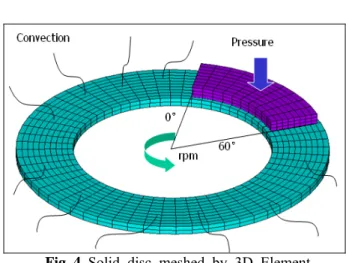
The model is symmetric about the central crossing plane of the brake disc. The cover angle of pad is 60°, from θ=0° (the exit of friction region) to θ=60° (the entrance of friction region). The Fig.4 shows the finite element model of the brake disc and pad. The disc and pad is meshed by 20nodes brick element. On the work surface of brake disc and pad, the frictional contact pair is defined to simulate the friction heat process. The total number of nodes is 8490, and total number of elements is 2242. The pressure 2.38MPa is applied on pad to generate the brake force through the friction behavior between the brake disc and pad. The convective heat transfer coefficient is applied to the surfaces of brake disc.
Fig. 4 Solid disc meshed by 3D Element
4. Results
4.1 Temperature Distribution
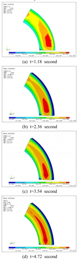
The Fig. 5 shows the temperature field in the disc during brake application. At the t=1.18 second, the maximum temperature is occurred around the mid circle of the contact surface (red area), called “hot spot”, temperature is 206.73℃. Subfigure (b) is the temperature distribution at t=2.36 second, maximum temperature is 236.84℃. The subfigure (c) shows the temperature at the t=3.54, temperature is 225.75℃. t=4.72 second is the end of time of the braking, maximum temperature in the disc is 180.56 ℃ . Comparing with t=3.54 second, the temperature distribution is difference: the decreasing of heat source (pads) moving velocity on the frictional surface causes the friction heat flux in a relative smaller swept area. At the same time, the effective of convective in the disc impacts on the temperature field. Based on the above two reasons, the temperature field presents approximately axisymmetic.
(a) t=1.18 second
398
(b) t=2.36 second
(c) t=3.54 second
(d) t=4.72 second
Fig. 5 Temperature distribution in the brake disc The Fig.6 plots the contour of the temperature field in the pad. It is presents a non-uniform characteristic.
The circumferential distribution: the maximum temperature is at the exit of contact region, temperature of entrance is relative lower. In radial direction, the temperature distribution is similar with the temperature field in the brake disc: maximum temperature is at mid circle of contact face of pad.
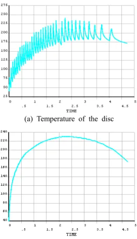
The subfigure (a) of Fig. 7 plots the temperature of the point on work surface of brake disc at r=10 5mm, θ=60° versus brake time during braking. The temperature curve is presented fluctuation in the bra king operation: the curve has many peaks, and the t emperature decreased rapidly after each peak. The te mperature is due to the moving heat source with va riable sliding speed that cause a variable heat flux i nto the difference domain of the disc work surface
and the cooling effect of the rest domain, in other words, the node that is on the work surface of the brake disc has one peak in the one revolution durin g the braking. The subfigure (b) shows the temperat ure curve of the maximum temperature node on the work surface of pad. The temperature increase nonli nearly, after the mid-time of the braking, the temper ature is decreased slowly.
(a) t=1.18 second
(b) t=2.36 second
(c) t=3.54 second
(d) t=4.72 second
Fig. 6 Temperature distribution in the pad
399
5
(a) Temperature of the disc
(b) Temperature of the pad
Fig. 7 Temperature of the point on frictional surface 4.2 Contact Pressure Distribution
The Fig.8 plots the non-uniform contact pressure distribution in the frictional interface of pad. The maximum contact pressure is occurred at the entrance of friction region, and descends towards the exit of friction region in the left subfigure (t=1.18s). According to equation (2), the sliding velocity increased linearly from the inner radius to the outer radius, and the non-uniform contact pressure distribution, these two reasons cause the temperature field of the brake disc and pad presenting non-uniform characteristics.
Fig. 8 Contact pressure on the work surface of the pad
5. Conclusions
The simulation identified the temperature field in the solid brake disc and pad based on the thermo-mechanical coupling model. For the point on the frictional interface of the brake disc, the temperature curve has multi peaks in the brake operation, and the temperature of the pad is increased nonlinearly before the mid-time of braking, and then decreased slowly.
The pressure is applied to the thermo-mechanical coupling model to simulate the process of heat produced by friction. The contact pressure presents the non- uniform characteristics in the contact pair between the brake disc and pad, caused by the friction of the contact pair. The non-uniform contact pressure and sliding speed lead to the non-uniform temperature field.
Acknowledgment
This research was financially supported by the Ministry of Education, Science Technology (MEST) and Korea Industrial Technology Foundation (KOTEF) through the Human Resource Training Project for Regional Innovation.
Reference
(1) Lee, K. J., 1999, “Numerical Prediction of Brake Fluid Temperature Rise during Braking and Heat soaking,” Proc. SAE 1999 World Congress, Detroilt, Michigan, SAE International 1999-01-1483.
(2) Valvano, T. Lee, K. J., 2000, “An Analytical Method to Predict Thermal Distortion of a Brake Rotor,” Proc. SAE 2000 World Congress, Detroilt, Michigan, SAE International 2000-1-0445.
(3) Gao, C. H., Lin, X.Z., 2002, “Transient Temperature Field Analysis of a Brake in a Non- axisymmetric Three-dimensional Model,” Journal of Materials Processing Technology, Vol.129, pp. 513- 517
(4) Gao,C.H., Huang, J.M., Lin, X.Z., Tang, X.S.,2007,
“Stress Analysis of Thermal Fatigue Fracture of Brake Discs Based on Thermomechanical Coupling”, Journal of Tribology Transactions of the ASME, Vol.
129, No. 3, 536-543.
(5) Hwang, P., Wu, X., Cho, S. W., Jeon, Y. B., 2007,
“Temperature and Coning Analysis of Ventilated Brake Disc based on Finite Element Technique,”
Hollywood, CA. SAE International 2007-01-3670.
(6) Wu, X., Hwang, P., Jeon, Y.B., 2007, “Thermal- mechanical Coupling Analysis of Solid Brake Disc in Repeated Brake based on Non-axisymmetric Three- dimensional,” KSME Fall Conference,
(7) Hwang, P., Wu, X., Jeon, Y.B., 2008, “Repeated Brake Temperature Analysis of Ventilated Brake Disc
400
on the Downhill Road,” San Antonio, Texas, SAE International 2008-01-2571
(8) Limpert, R., Brake Design and Safety, (Warrendale, PA: Science of Automotive Engineers Inc, 1992)
401