Keywords : Packed-bed(충진층), Liquid desiccant(액체흡수제), Solar collector(태양열 집열기), Dehumidification (제습), Mass transfer(물질전달)
[논문] 한국태양에너지학회 논문집
Journal of the Korean Solar Energy Society Vol. 26, No. 3, 2006
Research on Heat and Mass Transfer Coefficient in the Packing Layer With a Solar Desiccant
Heating/Cooling System
Eflita Yohana*, Choi, Kwang-Hwan**, Kim, Dong-Gyu**, Kim, Bu-Ahn***, Paek, Ki-Dong*, Kim, Ji-Won*
*Dept. of Refrigeration and Air-Con. Engineering, Graduate School, Pukyong Natl. University
**Dept. of Refrigeration and Air-Conditioning Engineering, Pukyong Natl. University
***Dept. of Materials Science and Engineering, Pukyong Natl. University
태양열 데시컨트 냉난방시스템 중 충진층에 있어서의 열․물질전달에 관한 연구
요한나*, 최광환**, 김부안***, 김동규**, 백기동*, 김지원*
*부경대학교 대학원 냉동공조공학과, **부경대학교 공과대학 기계공학부 냉동공조공학과
***부경대학교 공과대학 신소재공학부 재료공학전공
Abstract
최근에 에너지절약 차원에서 종래의 공조방식을 대신할 새로운 냉난방시스템 개발이 요구되고 있는데,
본 논문에서는 태양열 집열기를 이용하는 데시컨트 시스템 중 제습역할을 실질적으로 담당하는 제습기의
충진층 부분에서의 열 및 물질전달에 관한 일련의 해석 결과를 발표하고 있다. 제습과정에서 액체흡수제
는 충진층에서 열 뿐만 아니라 물질전달을 수반하게 되는데, 이 결과 건물에 냉방 및 난방효과를 가져다
준다. 따라서 이 충진층의 최적 설계가 시스템의 효율을 극대화하기 위해서는 무엇보다도 중요한데, 이를
위해서는 충진층에서의 열 및 물질전달 양상을 규명하여야 한다. 따라서 금번 실험에서는 공기와 액체흡
수제와의 접촉면적을 넓히기 위해서 충진재로써 3cm(직경) × 3cm(높이)인 시판중인 플라스틱 재질을
사용하고, 실질적으로 40cm(너비)×40cm(깊이)×40cm(높이)의 충진층을 직접 제작하여 실험을 행하였
다. 그 결과, 공기측 열 및 물질전달 계수는 공기 온도와 밀접한 관계를 갖고 있으며, 또한 물질전달계수
는 열전달계수와 같은 경향을 보이고 있음을 알 수 있었다.
Nomenclature
a : Specific internal surface for contact of gas with liquid, m
2/m
3a
A: Specific interfacial surface for desorption, m
2/m
3C
s: Heat capacity of liquid desiccant, J/kmol․K
d
s: Diameter of sphere of the same surface as single packing particle, m
D
L: Diffusitivety of liquid, m
2/s
F
G, F
L: Mass transfer coefficient for air and liquid respectively, kmol/m
2․s F
Ga, F
La : Volumetric mass transfer
coefficient for air and liquid respectively, kmol/m
3․s
G : Mass flux or flow rate per unit cross
‐section area, kg/m
2․s
G
’: Superficial gas mass velocity, kg(D) /m
2.s
H
s: Molar enthalpy of liquid stream, kJ/kmol
h
G, h
L: Heat transfer coefficient for air and liquid respectively, W/m
2․K h
Ga, : Volumetric heat transfer coefficient
for
h
La : air and liquid respectively, W/m
3․K j
D :Mass transfer group= F
GSc
G0.667G j
H :Heat transfer group= h
GPr
G0.667G k
G, k
L: Mass transfer for gas and liquid
respectively, kg/m
2.s
k
th: Thermal conductivity of liquid, W/m․K L
’: Superficial liquid mass velocity, kg/
m
2․s
M
L: Molecular weight of liquid, kg/kmol
m : Water evaporation rate(g/s) or per unit cross‐section area(g/m
2․s)
Pr
G, Pr
L: Prandtl number of air and liquid, respectively
t
G: Air temperature,
0C t
i: Interface temperature,
0C
Sc
G, Sc
L: Schmidt number for air and liquid, respectively
X, Y : Concentration of water in liquid and air respectively, mole fraction
X
i, Y
i: Concentration of water in liquid and air respectively, at interface, mole fraction
X
B,M: Mean concentration, mole fraction Z : Tower height, m
Greek symbols
ε : Void fraction volume in dry packed layer
ε
Lo: Void operation space in packing μ
G, μ
L: Viscosity of air and liquid, respectively, kg/m․s
ρ
G, ρ
L: Density of air and liquid kg/m
3Lt Ls Lo
φ φ
φ ,
,: Liquid operation, static, and total holdup, respectively
ξ : Concentration of the desiccant by mass, %
1. Introduction
There are two kinds of desiccant materials.
One is a solid desiccant, the other is a
liquid. Liquid desiccants, such as lithium
bromide, triethylene glycol, lithium chloride,
and calcium chloride solution, have a strong
concentration to absorb the moisture in
humid air. The merit using the liquid desiccant for handling the air is that it is easy to regenerate repeatedly under normal temperatures and relatively low pressure.
Liquid desiccant systems can provide cooling effects by only dehumidifying the air. If the strong liquid desiccant contacts the humid air directly and then it turns into the dilute after absorbing moisture out of the humid air. In order to reuse the desiccant in the system, it should be regenerated by solar energy up to a certain level of concentration.
Oberg and Goswami [1] have studied about several models to predict the performance of these kinds of systems, which are counter flow types with a packing layer for regeneration of the liquid desiccant. A finite difference model was often used to calculate an effectiveness of the heat and mass transfer in the packing layer, while being operated for dehumidification.
Elsayed et al [2] have also published papers concerning these phenomena.
Solar-heated hot water is used as a kind of heat source to extract water contained in the liquid desiccant. Though the temperature level is not very high, it is enough to regenerate the desiccant.
Choi et al [3] already developed a solar operated liquid desiccant system using lithium chloride as working fluid and made it clear that the regenerating speed can be increased rapidly when the solution temperature is above 50℃. Condensed water of 13kg as regeneration rate was acquired by operating 9 hours a day under fine weather.
The water evaporation transferred at the packing layer of regenerator was promoted much more than that of the case of a smooth flat plate.
Fathalah and Aly [4] carried out the experiments on the solid desiccant bed which was working in a solar power A/C system. It needed a LiBr-H2O adsorption cooling system, and the working fluid was regenerated by a heat rejected from a condenser of the machine. The regenerator should provide as large as possible specific surface area and extend a contacting time between liquid solution and humid air for the purpose of increased performance of heat and mass transfer in the packing layer.
Fumo and Goswami [5] have conducted the analysis regarding these respects by treating the matrix and desiccant separately. In this analysis, five governing differential equation models were introduced for explanation of heat and mass transfer within the matrix.
Furthermore S. Alizadeh and W.Y. Saman [6] investigated the characteristics of calcium chloride solution with different air volume and flow rate of solution under different air condition and solar radiation.
The results of the experiments indicated that the amount of water evaporated out of the weak solution increased as the air volume increased.
2. Experimental Set-up and Procedure
In this experiment, a 20%w.t.(weight
percentage) concentration of lithium chloride
was used as working fluid. Fig.1 shows the schematic of experimental set-up with a packing layer, which is a main component of a regenerator. The regenerator has a shape of a counter flow type to enhance the more intensive contact, though the higher fraction loss is. The weak concentration is sprayed from the top of packing layer by a magnetic pump and humid air is induced from a chamber by a blower. A regenerating system with the packing layer consists of a heat exchanger, pump and blower. The packing layer with a height of 50cm has a plastic packing material inside at random, which has a height of 3cm and diameter of 3cm. The pump capacity is 7ℓ/min. and blower air is 3.7㎥/s. Several electronic hygrometers were adopted to monitor the accurate behavior of the air.
The temperatures at several locations were measured by a thermocouple and recorded by a data acquisition system during the experiments. Especially, 20 points of temperature inside the packing layer were strictly checked for more precise analysis.
Owing to the heating effect in winter instead of cooling in summer, hot and humid air was induced from the lower part of column and leaves through the upper part as a state of the low and dried air. At this time concentrated liquid desiccant was sprayed from the top with a low temperature and a high concentration, and leaves with high temperature and low concentration.
Fig.1 A Schematic of liquid desiccant regenerator
3. Methodology
The ultimate objective of the regenerating process is to transfer more water from the weak desiccant solution to the air stream.
On the contrary, the water vapor is removed
from the humid air to desiccant solution
during dehumidifying. The driving force for
regenerating has a close relationship with a
difference between the vapor pressure of
the desiccant and the air. As long as the
partial vapor pressure of the water in the
desiccant is higher than air vapor pressure,
mass transfer can take place between
them. In order to investigate the accurate
performance of packing layer in regenerator,
several design parameters that were
expected to affect the performance were
studied.
Fig. 2 A cross section of typical regenerator
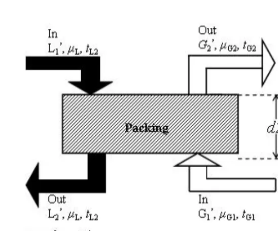
The interface temperature is normally equal to the temperature of the bulk liquid, since the resistance against heat transfer from the liquid side is negligible. The packing materials are adequately irrigated, i.e., the interfacial surface has the same area for heat and mass transfer and no axial dispersion occurs in the packing layer. A schematic diagram of a cross section of the packing layer was shown in Fig. 2.
The enthalpy of the liquid solution is defined as following:
Hs =Cs
(
ts −t0)
+ΔHs(1)
dHs =Csdts +dΔH(2)
In the packing layer, regeneration is a process accompanying heat and mass transfer at the same time. The driving force for regenerating is a dominant function of the difference potential for mass transfer.
This potential is the difference between the humidity ratio of air and the humidity ratio corresponding to the vapor pressure of
solution at the interface of the solution and air.
Heat and mass balances across the packing layer are normally established to evaluate the packing tower's performance.
The basic differential equations at any section are following as;
For heat transfer,
( )
p i G G G
c G
t t a h dZ dt
'
− −
=
(3)
For mass transfer,
( )
G' Yi Y Ga k dZ
dY −
−
=
(4)
Equation (4) also can be written like as,
⎟
⎠
⎜ ⎞
⎝
⎛
−
− −
=
Y Yi G
Ga F dZ dY
1 1
' ln
(5)
The variation of heat and mass transfer coefficients can be related to the following equation.
F
Ga = k
Ga . p
B,M(6)
The interfacial conditions are influenced
by properties of the liquid and air stream,
and it tends to be varied from point to point
in the column. The interfacial condition can
be obtained as;
( )
FGaLa F
Xi Y X
Yi
⎥
⎦
⎢ ⎤
⎣
⎡
−
− −
−
=
1 1 1
1
(7)
The equations must be solved simultaneously with the vapor-liquid equilibrium data.
a k a
F
Land
Lcan relate as follows;
L
L M B L
L M
X a k a
F ρ
. , .
=
(8)
Furthermore total holdup refers to the entire liquid in the packing layer under the operation, which is made up with two holdups, namely the operating condition and the static.
φ
Lt =φ
Lo +φ
Ls(9)
The interfacial area for evaporation of solution is given by following;
p n
m G L
m a
G
' ' 808
5 , 0
⎟ ⎟
⎠
⎞
⎜ ⎜
⎝
=
⎛
ρ
(10)
Where m, n and p are empirical constants and it would be given by Treybal [8]. In vaporization, the interfacial area is proportional to the entire holdup and the relationship is given as follows;
Lo
Lt
aA
a φ
85 φ ,
=0
(11)
The void fraction available for air flow in the packing layer is simply the difference of void fraction for the packing materials, the operating void space in the packing:
ε
Lo =ε
−φ
Lt(12)
For Raschic ring and Berl saddles, coefficient at air side is given as follow;
( )
667 , 0
36 , 0 1
' 195
. 1
G Lo G G
Sc G G d
F
s
−
= −
⎥ ⎦
⎢ ⎤
⎣
⎡
ε μ
(13)
Also mass transfer coefficient for the liquid side is given by following equation.
5 . 0 45 . ' 0 1
.
25 L
L L
L dsL Sc
ds
k D
⎟⎟ ⎠
⎞
⎜⎜ ⎝
=
⎛
μ
(14)
Through heat and mass transfer analogy, heat transfer coefficient based on air side can be calculated simply by assuming jD = jH
( )
667 . Pr 0
36 . 0 1
' 195 '
. 1
G Lo G p G
sG d C G h
−
= −
⎥ ⎦
⎢ ⎤
⎣
⎡
ε μ
(15)
and
Similarly, the equation for the heat transfer coefficient from the liquid side can be rewritten as following by using the Treybal equation[8]:
25.1 '
( )
PrL 0.5 Lth L
sL d ds
h k
⎥
⎦
⎢ ⎤
⎣
=
⎡
μ
(16)
The corresponding volumetric coefficient can be obtained by multiplying equation (13), (15) and (16) with “a”, specific internal surface for contact, from the basis of equation (11).
4. Result and Discussion
In this experiment the heat and mass transfer coefficient for the air side was calculated by making use of equations (8) - (16) for the packing layer with a height of 30cm.
Two correlation equations that would be useful in analyzing the performance of the packed tower was described. The formula for both coefficients are given as:
F
Ga = (L' ) (G' )
-0.4749(T
G)
-0.605H
Ga=0.9997(L' )
-0.0001(G' )
6.2559(T
G)
-0.605In the above formula, each value are also as following;
G' = 3.64 kg/m
2s , L'= 5 kg/m
2s, T
G= 9.1 to 12.5 ℃
Air side heat transfer coefficient
1500 2500 3500 4500 5500 6500 7500
8.5 10.5 12.5 14.5 16.5 18.5 20.5 22.5
Air side te mpe ra ture (0C) Volumetric heat transfer Coefficient (W/m3 K)_
(a)
Air side mass transfer coefficient
0.07 0.09 0.11 0.13 0.15 0.17 0.19 0.21
8.5 10.5 12.5 14.5 16.5 18.5 20.5 22.5
Air side tempe ra ture (0C ) Volumetric Mass transfer coefficient (kmol/m3.s)
(b)
Fig. 3(a), 3(b) Relationships between air temperature and heat and mass transfers, respectively