1. 서 론
국제해사기구(IMO) 산하 해양환경보호위원회 (MEPC, Marine Environmental Protection Committee)는 해양환경 보호 를 위해 2020년 1월부터 전 세계를 운항하는 400GT급 이상 현 존선 및 신조선을 대상으로 연료유 황산화물 함유량을 기존 3.5%에서 0.5%로 강화하여 규제하기로 결정하였다. 특히 북미 와 북유럽의 배출가스 규제지역 (ECA, Emission Control Areas) 에서는 황함유량이 0.1% 이하로 규제되며, 중국과 호주 연안으 로 확대 적용될 예정이다. LNG는 황산화물, 질소산화물 그리고 미세먼지 등의 환경오염 물질을 배출하지 않기 때문에 친환경 선박 연료로 주목받고 있다.
액화 LNG를 보관 및 운반하기 위한 다양한 화물창 종류가 있 지만, 멤브레인 화물창은 다른 LNG 화물창과 비교하여 제작비 가 저렴한 장점이 있어 많이 사용되고 있다. 다만, 멤브레인 화
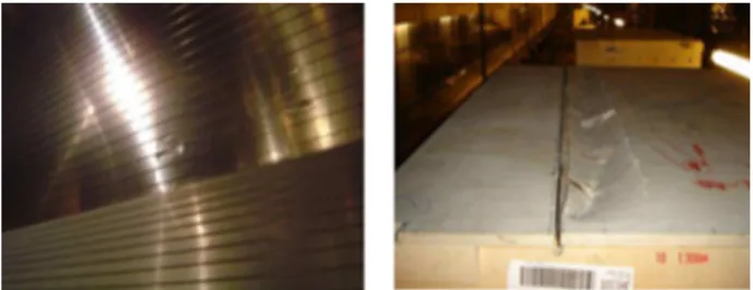
물창은 내부에 구조 부재가 없어 슬로싱에 의한 화물창 손상 가 능성이 큰 단점이 있다. 특히 부분 적재 조건에서는 격렬한 슬로 싱에 의해 높은 충격 하중이 발생할 가능성이 있다 (Pastoor et al., 2004; Zhao et al., 2004). Fig. 1은 2006년 138,000m3 LNGC인 Catalunya Spirit호에서 발생한 멤브레인 화물창 손상 사고 모습을 나타낸다 (Gavory & Seze, 2009). 따라서, 멤브레 인 화물창은 슬로싱 위험성 평가와 안전 설계가 매우 중요하다.
Fig. 1 Damages on membrane tanks
160K LNGC 멤브레인 화물창에 작용하는 슬로싱 충격 하중에 대한 비교 실험 연구
권창섭†・ 이영진・ 김현조・ 이동연
삼성중공업 조선해양연구소 선박해양연구센터
Comparative Experimental Study on Sloshing Impact Loads of LNG Cargoes in Membrane Containment System of 160K LNGC
Chang Seop Kwon†・ Young Jin Lee ・ Hyun Joe Kim ・ Dong Yeon Lee Samsung Heavy Industries Co., Ltd.
This is an Open-Access article distributed under the terms of the Creative Commons Attribution Non-Commercial License(http://creativecommons.org/licenses/by-nc/3.0) which permits unrestricted non-commercial use, distribution, and reproduction in any medium, provided the original work is properly cited.
A new state-of-the-art sloshing research equipment has developed to perform the model test of LNG tanks for the safer design of LNG cargo containment system in violent sloshing phenomena. This sloshing test system has developed by the Samsung Ship Model Basin (SSMB) and thoroughly verified. The accuracy of the motion of hexapods equipment for the excitation of a model tank has been verified. The maximum displacement in six degrees of freedom, harmonic motions of various frequencies, and irregular motions in wave conditions are measured and compared with input signals. In order to confirm the reliability of the post-processing program for measured impact pressure, the post-processed results were compared with those of the reference institute. A benchmarking sloshing test using 1/50 scale model of 160K LNGC tank was conducted for the verification of the whole testing system. The partial filing levels were considered. As a result of the experiment, it is confirmed that the results are in good agreement with those of the reference institute.
Keywords : Sloshing(슬로싱), Membrane Tank(멤브레인 화물창), Model Test(모형 실험), 160K LNGC(160K급 액화천연가스운반선)
슬로싱에 의해 화물창에 작용하는 충격 하중을 평가하기 위 해 다양한 실험적, 수치 해석적 연구가 수행되어 왔으나, 현재까 지는 모형 시험이 가장 신뢰성있는 방법으로 여겨지고 있다.
Kuo (2009)는 슬로싱 충격 하중 평가를 위한 시험법에 대해 체 계적인 연구를 수행한 바 있다. 삼성중공업은 보다 안전한 LNG 화물창 설계를 위해 슬로싱 실험 설비를 Samsung Ship Model Basin (SSMB)에 구축하였다. 슬로싱 실험 설비는 크게 화물창 모형을 강제 동요시키는 motion platform, 슬로싱 충격압 계측 시스템 그리고 충격압 후처리 프로그램으로 구성된다. 실험 기 관마다 다른 motion platform과 압력 계측 시스템, 해석 프로그 램을 사용하기 때문에 실험 결과의 일관성을 위해서 타 기관과 의 검증은 매우 중요하다 (Kim et al., 2012). 본 연구에서는 슬 로싱 실험 설비 검증을 위해 motion platform 구동 정확성 평가, 충격압 후처리 프로그램 신뢰성 검증 그리고 타 기관과의 비교 실험을 수행하였다.
2. 본 론
2.1 Sloshing Model Test System
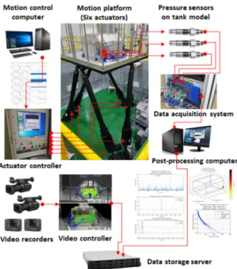
Fig. 2는 슬로싱 모형 시험을 위한 제어 및 데이터 계측 시스 템 구성도를 나타낸다. 크게 파도 중 선박의 거동을 재현하는 motion platform과 모형 화물창에 작용하는 압력을 계측하고 분 석하는 시스템 그리고 영상 녹화 시스템으로 구성된다. Motion platform은 6개의 actuator가 작동하는 hexapods 방식으로 작 동된다. 파도 중 선박의 6자유도 운동을 입력하면 actuator controller가 motion platform을 구동한다. 모형 탱크 안쪽 면에는
Fig. 2 Control and DAQ systems for sloshing model test
수십 또는 백여개의 압력센서가 설치된다. 계측된 압력 신호는 DAQ 장비를 통해 데이터 후처리 컴퓨터에 저장되고, peak data 및 통계처리된 데이터들은 데이터 서버에 저장된다. 그리 고 녹화된 탱크 내부 액체 유동 비디오들도 데이터 서버에 저장 된다.
2.2 Motion Platform
Motion platform의 용량은 220,000m3 LNGC에 대한 1/40 축 척비 실험이 가능하도록 설계되었다. Motion platform의 성능은 Table 1에 나타냈다. Actuator 구동을 위해서 Yaskawa사의 15kW급 서보 모터가 사용되었다. Motion platform이 정확히 구 동하는지 평가하기 위해서 광학식 6자유도 운동 계측 장비 (Krypton RODYM 6D)를 이용하여 platform의 움직임을 계측하 였다. 각 방향별 최대 변위, 복합 변위, 조화 운동 그리고 불규 칙 운동 조건에 대해 운동 입력값과 계측값을 비교하였다.
Table 1 Capacity of motion platform
Fig. 3 Input and measured signal for complex motion Item Displacement Acceleration Surge, Sway, Heave ± (800, 800, 600)mm 0.7G
Roll, Pitch, Yaw ± (40, 40, 55)deg 500deg/s2
Table 2 Accuracy of motion platform
unit Input Measure Error
Surge mm 800 803 0.375%
Sway mm 800 803 0.375%
Heave mm 610 610 0.000%
Roll deg 40.0 40.0 0.000%
Pitch deg 40.0 40.0 0.000%
Yaw deg 55.0 55.5 0.909%
Fig. 4 Input and measured signal for irregular motion Table 2는 단 방향 최대 변위 조건에서의 motion platform 정 확도를 정리한 것이다. Heave, roll, pitch 방향은 오차 없이 작 동하였다. Surge, sway는 0.375% 그리고 yaw는 0.909%의 오 차 범위 내에서 작동하였다. Fig. 3과 4는 복합 변위 및 불규칙 운동 조건의 platform 운동 입력과 계측값을 비교한 것이다. 불 규칙 운동 시계열은 북대서양 조건에서 160K LNGC motion을 1/50로 축소한 것이다. 두 조건 모두 motion platform의 입력값 과 계측값이 거의 일치하는 것을 확인하였다.
2.3 충격압 통계처리 프로그램 검증
서울대는 2012년에 다른 기관과 슬로싱 비교 검증 실험을 완 료하였다 (Kim et al., 2012). 160K LNGC에 대한 서울대 실험
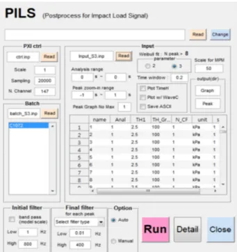
결과 (Park, 2014)를 기준으로 본 연구에서 개발한 충격압 후처 리 프로그램의 신뢰도를 검증하였다. 충격압 후처리 프로그램은 압력 신호 시계열 데이터로부터 peak값과 rise time, decay time 등을 분석하고 peak 데이터를 이용하여 weibull fitting, 3 시간 most probable maximum (MPM) 값을 계산하는 기능을 수 행한다. Fig. 5는 본 연구에서 개발한 충격압 후처리 프로그램 실행 화면을 나타낸다.
충격압 peak값은 기준치를 넘는 값만 분석하는 peak over threshold 방법을 사용하여 분석하였다. 비교 기관과 동일하게 peak pressure threshold와 time window는 2.5kPa, 0.2sec를 적용하였다. 구동 모터 진동 등의 노이즈 제거를 위해서 cut-off frequency 0.17 Hz의 high pass filter를 사용하였다 (LR, 2009).
Fig. 5 Post-processing program for impact signals 충격압 peak의 극한치 추정에는 보편적으로 3변수 Weibull 분포함수가 사용된다. 3변수 Weibull 분포함수의 누적확률밀도 함수(CDF, Cumulative distribution function)와 초과확률(POE, Probability of exceedance)은 아래 식으로 표현된다.
(1)
(2)
는 충격압 peak를 의미하고, 는 location parameter, 는 scale parameter, 는 shape parameter를 의미한다. 각각의 parameter는 모멘트법을 이용하여 구한다. Table 3과 Fig.6은 동일 압력 시계열 데이터에 대한 통계 처리 결과를 비교 기준값 과 비교한 것이다. Weibull 계수와 3시간 MPM 압력값이 기준값 과 잘 일치함을 알 수 있다.
Table 3 Comparison of statistical analysis results Reference Present Present
/Reference
Scale 3.4704 3.5518 102.3%
Shape 0.4918 0.4932 100.3%
Location 3.5382 3.5422 100.1%
3hr MPM (kPa) 144.20 143.62 99.6%
Fig. 6 Comparison of probability of exceedance plot
2.4 슬로싱 비교 실험
160K LNGC No.2 tank에 대한 서울대 슬로싱 실험 (Park, 2014)을 기준으로 비교 실험을 수행하였다. Fig. 7과와 8은 비 교 기관과 본 연구에서 사용한 160K LNGC No.2 tank의 1/50 축척비 모형 화물창을 나타낸다. 모형 화물창 제원은 Table 4와 같이 동일하다. 비교 기관은 투명 아크릴로 제작하였고, 본 연구 에서는 강성과 수밀을 보강하기 위해서 알루미늄으로 제작하였 다. 내부 유동 관찰을 위해서 한쪽 면과 일부 영역은 투명 아크 릴을 적용하였다.
Fig. 7 160K LNGC tank model (reference)
Fig. 8 160K LNGC tank model (present)
Table 4 Tank model size
Table 5는 실험에서 고려한 적재 높이와 파도 조건을 나타낸 다. 기존 실험에서 슬로싱 압력이 높게 나타난 조건을 선택하였 다. 적재 높이는 탱크 높이 기준으로 10, 20, 30, 40, 70, 95%
조건을 고려하였다. 적재 높이 95%H 조건은 북대서양의 40년 재현주기 파도가 파향 150도 조건으로 입사되는 조건을 고려 하였다. 참고로, 파향의 정의는 0도가 선미파, 90도가 우현에 서 다가오는 횡파를 의미한다. 나머지 적재 높이 조건은 90도 파향, 북대서양 1년 재현주기 파고 조건을 고려하였다. 파도 주기는 Tz 기준으로 7.5초에서 13.5초 범위가 고려되었다. 비 교 기관에서 사용한 motion platform 운동 시계열을 그대로 사 용하여 실험하였다. 실선 기준 5시간에 해당하는 실험을 수행 하고 Weibull 분포함수를 이용하여 3시간 MPM 압력값을 도출 하였다.
Table 5 Test condition
Item Value
Filling (%H) 10, 20, 30, 40, 70 95
Heading (deg) 90 150
Wave North Atlantic 1 year
North Atlantic 40 year Tz range (sec) 7.5 ~ 13.5
Fig. 9와 10은 압력센서 배치를 나타낸다. 낮은 적재 높이 조 건에서는 화물창 모형 측면에, 그리고 높은 적재 높이 조건에서 는 상부에 센서를 집중 배치하였다. 비교 기관은 낮은 적재 및 높은 적재 조건에 각각 150개와 147개의 압력 센서를 배치하였 고, 본 연구에서는 압력이 높게 나타난 위치를 선택하여 낮은 적 재 및 높은 적재 조건에 각각 61개와 78개의 센서를 배치하였 다. 센서는 클러스터 형태로 배치되었고, 황동 재질의 소켓을 사 용하였다. 압력 계측 주파수는 20kHz를 적용하였다.
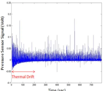
압력 센서로는 온도 영향이 작은 KISTLER사의 piezo- electric 타입 601 CBA 센서를 사용하였다. Piezo-electric type 센서는 반응 속도가 빨라 고주파수 계측이 필요한 충격 실험에 많이 사용되나, 온도 변화에 민감한 단점이 있다 (Kim et al., 2015). Table 6은 압력 센서 사양을 나타낸 것이다. Fig. 11은 모형 탱크를 규칙적으로 흔들어주었을 때, 수면 위에 위치한 압 력 신호 시계열을 나타낸다. 계측 초기에 압력 신호가 증폭된 것 처럼 보이는 것을 알 수 있다. 이는 공기와 닿아 있던 압력 센서 에 상대적으로 온도가 낮은 물이 닿아서 생기는 현상이다. 200 초 정도 시간이 지난 후에는 이러한 현상이 없어지는 것을 알 수 있다. 슬로싱 실험에서는 이러한 센서의 온도 영향을 피하기 위해서 300초 이후의 신호만을 사용하였다.
Item Tank length
Tank breadth
Tank height
Upper chamfer
Lower chamfer unit
(m) 0.93 0.76 0.57 0.17 0.08
Fig. 9 Pressure sensor location
Fig. 10 Tank model and pressure sensors
Table 6 Kistler piezo-electric type 601 CBA sencor
unit value
Max pressure bar 250
Sensing diameter mm 5.55
Natural frequency kHz > 215 Rise time sec < 1.4 micro second
Fig. 12는 슬로싱 실험에서 계측된 3시간 MPM 압력값을 비 교한 것이다. 압력값은 기준값 중 최대치로 무차원화되었다. 실 험을 수행한 모든 적재 높이 조건에서 기준값과 본 연구의 실험 결과가 잘 일치함을 확인하였다. 실험 결과를 토대로 볼 때, 3시 간 MPM 압력값에는 아크릴과 알루미늄 재질에 따른 영향이 크
지 않은 것으로 판단된다. 추후 탱크 모형의 재질, 표면 거칠기 에 따른 충격압의 영향에 대해 규칙 운동 또는 1회 충격만 발생 하게 하는 single impact wave test 등을 통한 정밀 비교 분석이 필요하다고 사료된다.
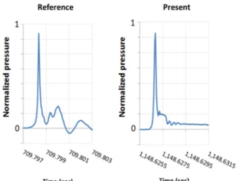
Fig. 13은 슬로싱 압력이 높게 나타난 조건에서 같은 위치에 충격압 peak가 비슷한 수준으로 나타난 압력 신호를 비교한 것 이다. 두 신호는 상대 비교를 위해서 같은 값으로 무차원화되었 다. 최대치 이후에 압력이 감소하는 구간의 진동 패턴은 다소 다 르게 나타났다. 슬로싱 충격 시, 물과 공기가 혼합된 비율 또는 포획된 공기의 양 등에 따라 압력 감소 구간의 진동 패턴은 달 라질 수 있다.
슬로싱 압력이 높게 나타난 조건에서 불규칙파의 wave random seeds를 바꿔가면서 총 4회 실험을 수행하였고, 최소, 최대, 1사분위, 3사분위 및 중앙값을 Fig. 14에 비교하였다. 마 찬가지로 기준값과 유사한 수준으로 나타났다. Fig. 15는 슬로 싱 압력이 높게 나타난 조건에 대해서, 동일한 motion으로 6회 반복 실험한 결과를 나타낸 것이다. 평균값을 기준으로 최대 15% 범위의 편차를 보였다.
Fig. 11 Thermal drift effect on pressure sensor
Fig. 12 Comparison of sloshing test results
Fig. 13 Comparison of impact pressure signals
Fig. 14 Wave random seeds variation test results
Fig. 15 Repeat test results
3. 결 론
슬로싱 모형 실험은 LNG 화물창 또는 연료탱크에 작용하는 슬로싱 충격 하중을 평가하기 위한 현실적으로 가장 신뢰성있는 방법이다. 실험 기관마다 다른 motion platform과 압력 계측 시 스템 및 해석 프로그램을 사용하기 때문에 실험 결과의 일관성 dmf을 위해 타 기관과의 비교 검증은 매우 중요하다. 본 연구에 서는 새로 구축된 motion platform의 움직임을 계측하여 입력 신호와 비교함으로써 정확도를 확인하였다. 그리고 비교 기관의
데이터를 이용하여 독자적으로 개발한 충격 압력 신호 후처리 프로그램을 검증하였다. 또한 160K LNGC 화물창에 대한 1/50 축척비 조건에서 기존 실험 결과와 비교 실험을 수행하였다. 결 론적으로, 부분 적재 조건을 포함하여 실험이 수행된 모든 적재 조건에서 기존 실험 결과와 잘 일치함을 확인하였고, 일관성 있 는 결과를 얻을 수 있음을 검증하였다.
References
Gavory, T. & Seze, P., 2009. Sloshing in membrane LNG carriers and its consequences from a designer’s perspective. 19th International Society of Offshore and Polar Engineers, pp.1-8.
Kim, S. et al., 2012. Comparative study on model-scale sloshing tests. Journal of Marine Science and Technology, 17(1), pp.47-58.
Kim, S., Kim, K. & Kim, Y., 2015. Comparative study on pressure sensor for sloshing experiment. Ocean Engineering, 94, pp.199-212.
Lloyd’s Register, 2009, Sloshing assessment guidance document for membrane tank LNG operations, pp.27.
Park, J., et al. 2014. Sloshing assessment of LNG vessels for unrestricted tank filling operation. Proceedings of the 24th International Ocean and Polar Engineering Conference, Busan, Korea, pp.108-113.
Pastoor, W., Tveitnes, T., Valsgard, S. & Sele, H. 2004. Sloshing in partially filled LNG tanks – an experimental survey.
Proceedings of Offshore Technology Conference, Houston, TX, USA.
Zhao, R., Rognebakke, O. and Zheng, X. 2004. Wave and impact loads in design of large and conventional LNG ships.
Proceedings of RINA Conference of Design and Operation of Gas Carriers, London, UK.
권 창 섭 이 영 진 김 현 조 이 동 연