Vol. 21, No. 5, pp. 558-570, October 31, 2015, ISSN 1229-3431(Print) / ISSN 2287-3341(Online) http://dx.doi.org/10.7837/kosomes.2015.21.5.558
A Study on the Green Ship Design for Ultra Large Container Ship
Mingyu Kim Dong-Woo Park
* Dept. of Naval Architecture, Ocean and Marine Engineering, University of Strathclyde, Glasgow, UK
** Dept. of Naval Architecture & Ocean Engineering, Tongmyong University, Busan 48520, Korea
대형 컨테이너 운반선의 그린쉽 설계에 관한 연구
김민규 박동우
* 스트래스클라이드대학교 조선해양공학과, ** 동명대학교 조선해양공학과
Abstract : A study on the green ship design for Ultra Large Container Ship (ULCS, 18,000 TEU Class Container Ship) was performed based on the four step procedures of the initial design and hull form optimization to maximize economic and propulsive performance. The first, the design procedure for ULCS was surveyed with economic evaluation considering environmental rules and regulations. The second, the characteristics of single and twin skeg container ships were investigated in view of initial design and performances. The third, the hull form optimization for single and twin skeg ships with the same dimensions was conducted to improve the resistance and propulsive performances at design draught and speed by several variations and the results of the optimization were verified by numerical calculations of CFD and model test. The last, for the estimated operating profile of draught and speed, the hull forms of single and twin sked ships were optimized by CFD. From this study, the methodologies to optimize the hull form of ULCS were proposed with considerations during the green ship design and the improvement of the energy efficiency for the optimized hull forms was confirmed by the proposed formula of the total energy considering design conditions, operating profile and fuel oil consumption.
Key Words : Green ship design, Ultra large container ship (ULCS), Single-skeg ship, Twin-skeg ship, Optimized hull form, Computational fluid dynamics (CFD), Model test at towing tank, Operating profile
요 약 : 18,000 TEU 급 대형 컨테이너 운반선의 그린쉽 설계에 관한 연구로 기본설계와 에너지 효율 향상 관점에서 선형 최적화 과 정을 4단계로 나누어 체계적으로 연구를 수행하였다. 첫째, 환경적 측면 및 법규 등을 고려하여 대형 컨테이너 운반선의 경제성 평가를 수행하였다. 둘째, 기본설계 및 성능 관점에서 단축선형과 쌍축선형의 특징을 조사하였다. 셋째, 설계 흘수 및 속도에서 저항과 추진 성 능을 향상시키기 위한 단축 및 쌍축선의 선형 최적화를 CFD와 모형시험을 통해 수행하였으며 최적 선형의 성능 향상을 확인하였다. 마 지막으로 실제 운항조건을 고려한 추정된 운항 흘수와 속도에서 CFD를 통해 최적화된 최종 선형을 제시하였다. 본 연구를 통해서 대형 컨테이너 운반선의 그린쉽 설계를 위해 고려해야 할 사항을 살펴보았고 그에 따른 선형 최적화를 수행하였으며 설계 흘수와 실제 운항 조건 및 연료 소모량을 고려한 총 에너지 효율식을 이용하여 최적화된 단축 및 상축 선형의 에너지 효율 개선을 확인하였다.
핵심용어 : 그린쉽 설계, 대형 컨테이너운반선, 단축선형, 쌍축선형, 선형최적화, 전산유체역학, 모형시험, 실제 운항조건
1
1. Introduction
The growth in size of container ships has been one of the major achievement of the marine industry, which is expressed as economy of scale recently. The early container ships in the late 1960s had capacities of around 1,000 TEU. Since then, driven by economy of scale, container ship owners have been interested in larger ships,
* First Author : [email protected]
Corresponding Author : [email protected], 051-629-1654
now reaching capacities of 18,000 TEU and even more.
Aside from the issue of the container ship size, today’s another big issues are high fuel oil price and global climate change which induce the shipyards and ship owners to mitigate fuel oil consumption and several marine pollution such as exhaust gas (SOx, NOx, Green House Gas, i.e. CO2, etc.) (Choi et al., 2013), water pollution (ballast water, bilge water, anti-fouling material, noise, etc.), waste delivery ashore (oil/chemical residues, wastes, etc.), hazardous materials and ship recycling. These topics force
Main design items Factors
Main dimensions and particulars LOA/LBP, breadth, depth, block coefficient (CB), ship speed, design and scantling draught, DWT, etc.
Hull form, propeller and rudder hull form optimization, number of propeller blades, propeller diameter, rudder type, ESD, etc.
Main engine and generator number of propulsor, main engine type, power, and tuning method, LNG fuel, generator type and capacity, WHRS, etc.
Outfittings and piping Mooring equipments, hatch cover, lashing bridge, ballast and fuel oil pump, piping equipments, BWTS, etc.
General arrangement and specifications rules and regulations, stability, container (nominal, loadable and reefer) capacity, ballast water and fuel oil tanks, etc.
requirement of ship owner, charterer
and others sea route, canal, port, specific required rules and regulations, flag, air draught, still water bending moment, etc.
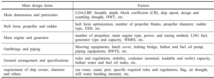
Table 1. Main design items and factors for container ship marine industry to act and find ways to design and operate ships more environmental friendly and economically.
Aside from the issue of the container ship size, the International Maritime Organization (IMO) currently has developed Energy Efficiency Design Index (EEDI) (Resolution MEPC. 203(62), 2011) in order to benchmark different designs and use the EEDI as a requirement for a minimum performance for fuel efficiency and GHG (Green House Gas) emissions (Choi et al., 2015) which will be controlled through new IMO legislation which comes into force on January 1, 2013. In future years, the EEDI will restrict CO2
through phased reductions in limits. in much same way that MARPOL Annex VI has regulated SOx and NOx emissions.
In this work, the four step procedures of the initial design and hull form optimization to maximize economic and propulsive performance are presented for ULCS.
The first, initial design procedures are described for ULCS with economic assessment under environmental regulations and various requirements of potential ship owners with design items and factors to be considered.
The second, the characteristics and performance of single and twin skeg ships are compared based on information from initial design and optimized hull form for both ships in this paper.
The third, hull form optimization to improve resistance and propulsive performance at design draught and speed was conducted for single and twin skeg ships with the same dimensions by several variation and optimized hull form for each skeg type was derived through comparison and analysis with the results of CFD and model tests.
The last, hull form optimization at initially estimated range of
draught and speed based on operating profile of previous two other size ships already optimized was studied using single and twin skeg hull forms optimized at design draught and speed. In addition, initial and optimized hull form are evaluated by the formula of total energy considering an economic and real operation perspective and performance comparison with trim variation for optimized hull form are conducted to reduce fuel consumption further in operation.
2. Initial design procedure of container ship
The global climate change and high fuel oil price drive shipyards to design a container carrier competitively at initial design stage and consider forced environmental regulations and various requirements/specifications of potential ship owners lately.
Also, recently, there are many researches and projects to improve the efficiencies in view of real operation of ships at sea (e.g. route optimization with weather (e.g. wind and wave), minimization of carried ballast capacity, maximizing the number of deck containers with improved cargo lashing system and port efficiency with increasing the capacity of cranes).
These sudden changes of circumstance require ship designers to innovate their existing ship design, take creative design concepts or equipments including main engine and even study technical idea, energy saving device (ESD) (Hollenbach and Reinholz, 2010), etc.
Table 1 is summarizing items and relevant factors to be considered in initial design stage for container ships.
These factors are complicatedly interrelated so that container ships need to be designed under rules and regulations, economic
Main dimension and particular (LOA, B, depth, draught, CB, speed, etc.)
Speed-power prediction and hull form design/optimization
Structural design (scantling, key plans, etc.)
Main engine
(number, type, MCR/NCR, tuning, etc.)
Generator (type, reefer capacity, etc.)
Outfitting equipment (mooring, hatch cover, lashing, maneuvering, etc.)
Piping equipment (pump, piping, etc.)
General arrangement and calculation
(compartment arrangement, accommodation, tank capacity, stability, etc.)
Ship specification and estimated price
Prospect of global demand, requirements of potential ship owner, rules and regulations, route and canal, safety and habitability, etc.
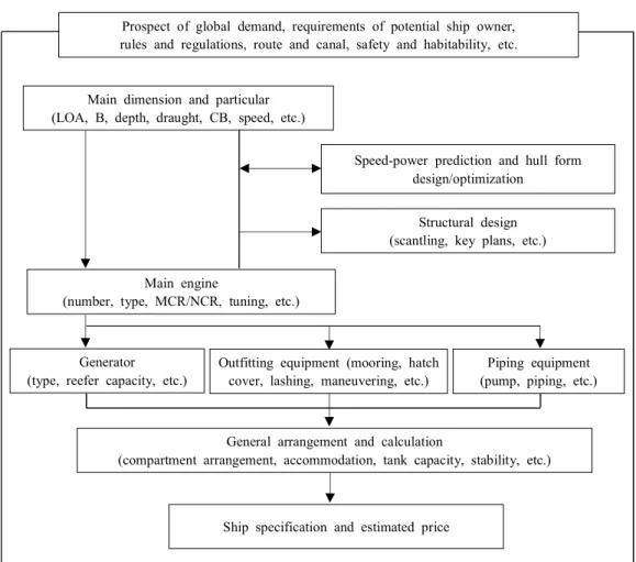
Fig. 1. Procedure of Initial design for a container carrier.
Fig. 2. General arrangement of 18,000TEU twin skeg container ship.
evaluations (e.g. transportation profit/(ship price and operating cost), DFOC/loadable container capacity or g/TEU/nautical mile) and requirements of ship owners.
For example, if a container ship is designed to have larger block coefficient (CB) than initial ship in order to carry more DWT and containers, hull structure, main engine power and daily fuel oil consumption (DFOC) would be increased and finally ship price and operation cost would be also increased.
At the initial design stage, variations of main dimension and particular are carried out several times for similar size of a container ship to maximize economic and fuel efficiency under given or fixed requirements, which look like design spiral to concentrate on optimized ship design. The diagram of initial design for ULCS is simply presented in Fig 1. Recently, 18,000TEU container ship has been designed for single and twin skeg hulls reflecting safety, easy access, stability, rules & regulations
Ship type Single skeg ship Twin skeg ship Remark
Initial design Verified Complicated
Resistance performance B W Twin skeg has larger wetted surface area
Propulsive performance W B Twin skeg has better wake flow on propeller
Required power S S
Deadwight, DWT B W Light weight of twin skeg is bigger
Container capacity S S Nominal capacity
Redundancy W B
Maneuverability W B
Noise and vibration W B
Initial investment cost B W
Note : B : Better than another skeg ship, S : Similar for both skeg ship, W : Worse than another skeg ship Table 2. Comparison of characteristics for single and twin skeg ships
(SOLAS, MARPOL, ICLL, Class, etc) and above all items and factors. Fig. 2 shows the general arrangement of the designed 18,000 TEU Class twin skeg container ship.
3. Characteristics of single and twin skeg container ships
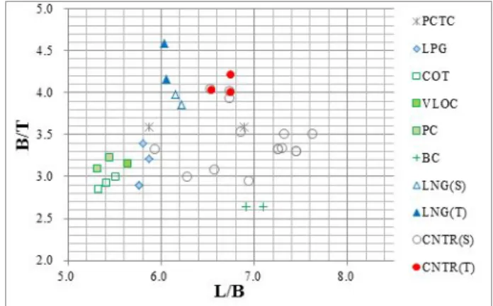
Twin skeg ship was investigated alternatively because ULCS has relatively wider breadth (B) in comparison with LBP (L) and design draught (T). Large ships with wide breadth were expected to be suitable for the application of twin skeg hull from the investigation of database system as shown in Fig. 3. Both hull types have their own benefits. The major advantages of twin skeg container ship are better maneuverability, less noise and vibration and having redundancy which are gained as having two individual machinery plants. However, twin skeg ships need higher initial investment.
Fig. 3. Database analysis with B/T and L/B of vessels.
Main characteristics of single and twin skeg ships are compared in Table 2.
In the above table, the estimation of power performance is based on model tests as well as CFD calculations for single and twin skeg hull forms which are optimized by studying several hull forms with a variety of variation during substantial period. Detail results of hull form optimization will be described later.
The difference of required power at design draught between single and twin skeg ship is expected to be similar at design speed, 23 knots.
In case of application for longer stroke than present main engine to this vessel, it will be able to make fuel oil consumption to be reduced slightly by lower main engine speed and larger propeller diameter which increase propeller efficiency (Carlton, 2007) even though the small loss of container capacity in hold would be expected and limitation of propeller diameter should be considered for manufacture, real operation draughts, hull-propeller clearance with respect to noise and vibration and additional ballast water capacity to immerse the larger diameter of propeller.
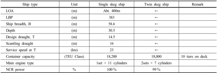
Both skeg type container ships have been initially designed with the same displacement at design draught. The comparison of the main particulars for designed single and twin skeg hulls are presented in table 3 where the figure of NCR power for single skeg ship is assumed as 100 % for comparison with twin skeg ship.
4. Procedure of hull form optimization
In order to reduce consumption of the fuel oil which price is predicted to increase as time goes on, the first priority is to design a container ship with better energy efficiency. It means that the
Ship type Unit Single skeg ship Twin skeg ship Remark
LOA (m) Abt. 400m ←
LBP (m) 383 ←
Ship breadth, B (m) 58.6 ←
Depth (m) 30.5 ←
Design draught, T (m) 14.5 ←
Scantling draught (m) 16 ←
Service speed at T (kts) 23 ←
Container capacity (TEU Class) 18,200 18,000 10 tiers on deck
Main engine type 1set × 11 cylinders 2sets × 7 cylinders
NCR power % 100 % 99 %
Table 3. Comparison for designed single and twin skeg container ships
ship designers and ship owners are getting more and more interest in reducing propulsion power of ships and optimizing hull form.
Hull form optimization was conducted for single and twin skeg hull forms based on given main dimensions with same displacement.
The procedure of hull form optimization used in the present work is presented in Fig. 4.
Fig. 4. Procedure of hull form optimization.
In the course of hull form optimization, all comparison and evaluation of performance between initial and optimized hull form at each variation step ware analyzed by CFD calculation which method has been verified, validated quantitatively as well as qualitatively and sufficiently supported to develop the hull form.
The variation methods for hull form optimization at design
draught and speed are summarized in table 4. For single skeg ship, optimization for forward hull form including bulbous bow variation was conducted mainly. The stem hull form of twin skeg hull was modified and developed by using the stem of single skeg after study of optimum Longitudinal Center of Buoyancy (LCB) position. And then, optimization of twin skeg hull form was investigated around stern skegs.
Variation
method Single
skeg hull Twin
skeg hull Remark
LCB position - done
Bulbous bow done - Bulb area, height and length
Stern skeg - done Vertical angle and distance between stern skegs Stern hull form done done
Table 4. Applied variation methods for 1st hull for optimization
5. Numerical method for hull optimization
The numerical calculation was conducted to optimize the hull form by using a commercial CFD code (WAVIS ver.2) (Kim et al., 2011) which has been developed by Korean Research Institute for Ships and Ocean Engineering (KRISO) and is able to generate the grid of the single skeg hull automatically and calculate potential and viscous free surface flow with the change of trim and sinkage of ships and self-propulsion performance of ships by solving interaction between viscous free surface flow of hull and propeller influence from calculation based on lifting surface theory.
The main characteristics of CFD code are RANS (Reynolds
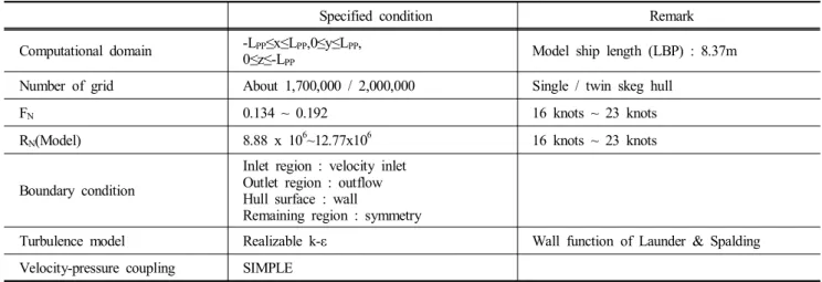
Specified condition Remark Computational domain -LPP≤x≤LPP,0≤y≤LPP,
0≤z≤-LPP Model ship length (LBP) : 8.37m
Number of grid About 1,700,000 / 2,000,000 Single / twin skeg hull
FN 0.134 ~ 0.192 16 knots ~ 23 knots
RN(Model) 8.88 x 10⁶~12.77x10⁶ 16 knots ~ 23 knots
Boundary condition
Inlet region : velocity inlet Outlet region : outflow Hull surface : wall
Remaining region : symmetry
Turbulence model Realizable k-ε Wall function of Launder & Spalding
Velocity-pressure coupling SIMPLE Table 5. Computational conditions
Averaged Navier-Stokes) method for governing equation, Finite Volume Method (FVM) for integration and LS (Level-Set method) for the effect of free surface.
The coordinate system (x, y, z) is defined as positive x in the flow direction, positive y starboard and positive z upward where the origin locates at the intersection of center plane, amidships and undisturbed free surface.
The flow computational conditions of flow field are summarized in Table 5. All numerical calculations of hull form optimization for both skeg ships were conducted by application of viscous free surface flow for the hull with rudder and propeller influence solving the unsteady hull-propeller interaction using propeller body force distribution based on lifting surface theory.
In this work, a commercial grid generation code was used to make surface and spatial grid system. The distance of the first grid point of the ship surface was maintained 50 < y+ < 150 that is within a low-law region.
6. Hull form optimization
Table 6 shows applied variation methods in order to optimize the hull form for single and twin skeg ships.
6.1 Hull form optimization
16,000TEU single skeg ship designed at relatively high speed, 25.5 knots (Fn=0.214), was selected for initial hull form from data base system and modified to initial hull form (Ship SI) of single skeg ship.
Main viewpoints to optimize single skeg hull form are bulbous bow design to mitigate bow and breaking wave at relative slow
design speed, 23 knots (Fn=0.193) and stern hull form design to increase propulsive performance.
Variation method Single
skeg hull Twin
skeg hull Remark
Bulb area done - The stem hull form
of twin skeg was modified by using optimized stem hull form of single skeg
Bulb height done -
Bulb length done -
LCB1) - done
Vertical angle of skeg - done Distance between
skegs2) - done
Stern hull form done done
1) afterward from amidship, % : (LCB distance/LBP) × 100 2) (distance of skegs / breadth of the vessel) × 100 Table 6. Applied variation methods to optimize hull form
6.1.1 Bulbous bow variation
Bulbous bow variation was conducted step by step for area, height and length which definition is presented in Fig. 5.
Fig. 5. Definition of bulbous bow variation.
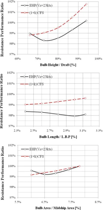
Fig. 6 shows the CFD calculation results with each variations of bulbous bow in view of resistance performance ratio (the ratio of the total resistance for the optimized hull (Ship SA) compared with the initial hull form (Ship SI), Effective Horse Power (EHP) which consists of viscous ((1+k)CFS) and wave resistance (CR)) mainly.
All data and results of the CFD calculation were extrapolated to the full scale using ITTC 1978 Performance Prediction Method (ITTC, 1978).
Fig. 6. Resistance performance with bulb variation.
6.5 %, 73 % and 3 % for bulb area, height, and length respectively are the most superior performance in resistance and the total improvement between initial hull (Ship SI) and optimization hull (Ship SA) for bulbous bow was 2 % in EHP as shown in Table 7.
Ship SI Ship SA Remark
Bulbous bow Configuration
Area / Midship 7.8 % 6.5 % Height / Draft 87.0 % 73.0 % Length / LBP 2.4 % 3.0 %
Resistance Performance (EHP) 100.0 % 98.0 % 2 % saving Table 7. Comparison of bulbous bow configuration between Ship
SI and SA
From the study on the variation of bulbous bow, the height of bulbous bow took the largest effect on the performance of resistance. The comparisons of wave contour, pressure distribution on the hull surface at each station are depicted in Figs. 7 and 8.
As known as figures below, wave height and pressure contour of the optimized hull form (Ship SA) are much less and smoother, which means that the resistance performance of the optimized hull form is much better.
Fig. 7. Comparison of wave height distribution.
Fig. 8. Comparison of pressure and wave height distribution on the hull.
6.1.2 Stern hull form variation
Stern hull form was developed to make the inflow velocity to the propeller plane more uniform which maximize the propulsive performance.
Fig. 9 shows axial nominal velocity (without propeller rotating) distribution at each angle. As for Ship SA, total mean velocity of inflow to the propeller was faster and total uniformity of velocity was improved, especially from 0˚ to 60˚ which is also related to the performances of the propeller cavitation and vibration.
Finally, optimized hull form (Ship SA) was obtained through additional empirical modification for stem hull form. Table 8 summarizes the performance difference between initial hull form (Ship SI) and optimized hull form (Ship SA) which shows total 5.6 % saving of delivered horse power (DHP) through the hull form optimization.
Fig. 9. Axial velocity contour at propeller plane at 23 knots.
Hull EHP DHP Remark
Ship SI 100.0 % 100.0 %
ηD for Ship SA is improved by 2.4 %
Ship SA 96.6 % 94.4 %
Saving -3.4 % -5.6 %
Table 8. Comparison of CFD calculation results (at 23 knots, Fn=0.193)
6.2 Optimization of twin skeg hull form
Hull form optimization for twin skeg was investigated on the position of LCB, vertical angle of skeg and distance between skegs. After study of optimum LCB position, the stem of twin skeg hull was modified and developed by using the stem hull form for single of skeg.
Main viewpoints to optimize twin skeg hull form are to find optimum LCB position to minimize the resistance performance and skeg configuration to maximize the propulsive performance (Park et al., 2007).
6.2.1 LCB variation
There was not much study on optimized LCB position for twin skeg hull form so that influence on the change of the LCB position was investigated in this work.
Generally, if forward LCB position makes wave resistance worse because forward hull form becomes blunt, on the other hand, the slender stern hull form makes the performance of friction or hull resistance better.
In this study, resistance performance is improved at -1.97 % of LCB position by about 1 % from the initial hull form (Ship TI) as shown in Table 9.
LCB position(%) 1) EHP (%) Remark
-0.47 1.39
-0.97 0.70
-1.47 0.00 Initial hull form (TI) -1.97 -0.92 Optimized hull form (TA)
-2.47 0.61
-2.97 4.17
1)afterward from amidship, % : (LCB distance / LBP) x 100 Table 9. Comparison of resistance performance with LCB position
Fig. 10. Definition of vertical angle and distance between skegs in stern skeg arrangement.
(a) Skeg vertical angle (clockwise: +, counter clockwise: -) (b) Skeg distance
6.2.2 Vertical angle variation of skeg
Variation of skeg for twin hull form was carried out for skeg vertical angle and distance between skegs which definition are presented in Fig. 10.
First, vertical angle variation of skeg was conducted to improve the propulsive performance.
Table 10 shows the simulation results of the resistance and propulsive performances with variation of the vertical skeg angle, which indicates that as vertical angle increases, resistance performance is getting better, but on the contrary propulsive performance is getting worse. From the simulation results, -15˚ was chosen as the optimized skeg angle with the improvement of DHP by 2.2 % compared with the optimized hull form for LCB.
Table 10. Comparison of resistance and propulsive performance with vertical angle of skeg
Vertical
angle EHP
(%) ηD
(%) DHP
(%) Remark
-5˚ 100.0 100.0 100.0 Initial hull form (TI)
-10˚ 97.4 99.4 98.0
-15˚ 96.4 98.6 97.8 Optimized hull form (TA)
-20˚ 96.2 97.9 98.3
6.2.3 Distance variation between stern skegs
Hull form variation for the distance between skegs was conducted. It was investigated that the distance between skegs takes effect on resistance performance much and optimized distance is about 40.2 % compared with the ship breadth as summarized in Table 11.
Distance between skegs
EHP (%) ηD
(%) DHP
(%) Remark
37.50 % 101.4 100.2 101.1
40.20 % 100.0 100.0 100.0 Initial and optimized hull form
42.70 % 102.4 100.1 102.0
Table 11. Comparison of resistance and propulsive performance with distance between skegs
Finally, optimized twin skeg hull form (Ship TA) was obtained through additional empirical modification for stem hull form.
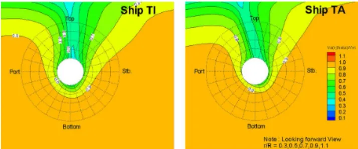
Fig. 11 shows axial nominal velocity distribution at each angle, which indicates that total mean velocity and uniformity of inflow velocity to the propeller was considerably improved for Ship TA compared with those of Ship TI.
Fig. 11. Comparison of nominal wake velocity.
Table 12 summarizes the performance difference between initial hull form (Ship TI) and optimized hull form (Ship TA) which shows total 7.9 % saving of DHP through the hull form optimization which includes lots of hull form variations, CFD calculations and analysis.
Hull EHP ηD DHP
Ship TI 100.0 % 100.0 % 100.0 %
Ship TA 94.9 % 103.0 % 92.1 %
Saving -5.1 % 3.0 % -7.9 %
Table 12. Comparison of resistance and propulsive performance for twin skeg hull
6.3 Model test results
Model tests were carried out in the towing tank at Hyundai Maritime Research Institute (HMRI) to validate the computational results for the hull form optimization and to evaluate the resistance and propulsive performance of optimized hull form. The dimension of the towing tank, maximum speed and type of wave maker are shown in Table 13. The extrapolation method to the full scale is using ITTC 1978 Performance Prediction Method. The model with scale ratio of about 1/45.76 was used in model tests.
Towing tank Dimension
(L × B × H) 210m × 14m × 6m
Carriage Max. speed 11 m/sec
Wave maker Type Flap type
Table 13. HMRI Towing Tank
Hull type Vs
(knots) W.S.A.* CTS EHP
Single skeg (Ship SA)
23
100.0 % 100.0 % 100.0 % Twin skeg
(Ship TA) 105.1 % 97.1 % 102.1 %
* : wetted surface area
Table 14. Comparison of resistance performance in model test 6.3.1 Model test for single skeg hull form
Model test of the final optimized hull (Ship SA) for single skeg hull of the vessel was carried out as shown in Fig. 12.
Fig. 12. model test of optimized hull (Ship SA).
6.3.2 Model test for twin skeg hull form
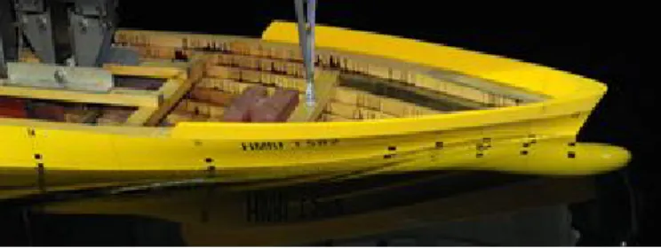
Model tests of final optimized twin skeg hull (Ship TA) were conducted. A ship model is shown in Fig. 13.
Fig. 13. A ship model of optimized twin-skeg ship.
6.3.3 Comparison between the results of single and twin skeg hull form
The resistance and propulsive performance at design draft (14.5m) and speed (23 knots, Fn=0.193) was compared for finally optimized single and twin skeg hull forms.
For optimized hull form for both skeg types, wave and form resistance coefficient of twin skeg hull is better than single skeg hull but the effective horse power for twin skeg hull is worse as shown in Table 14 because twin skeg hull has more wetted surface area than single skeg hull, which increases required resistance
power. Therefore, even though twin skeg hull has more wetted surface area, it is important to design stern skegs of twin skeg hull systematically to increase resistance performance.
It is widely known that propulsive performance of twin skeg hull is better than single skeg hull because twin skeg hull has better wake performance and two propellers bearing almost half power compared with single skeg hull at the same ship speed, which are able to reduce propeller load, be able to reduce Expanded Area Ratio (EAR) of propeller and even number of blades.
Propulsive performance for both optimized hull forms was predicted that hull efficiency of twin skeg hull was unfavorable but propeller efficiency is much better which lead to better propulsive efficiency finally as shown in Table 15.
Hull type Vs
(knots) ηD DHP
Single skeg (Ship SA)
23
100 % 100 %
Twin skeg
(Ship TA) 104.2 % 99.1 %
Table 15. Comparison of propulsive performance in model test
Therefore, it is important to design stern skegs systematically for twin skeg hull to increase propulsive performance and also properly propeller fitting to wake.
Even though model tests for initial hull forms of both hull types were not carried out, hull form optimization was conducted by a great amount of hull form variation, CFD calculations and analysis and improvement of resistance and propulsive performance was confirmed through model tests.
Also, as we expected by CFD calculation, both hull types optimized at design draught and speed shows similar required power performance.
7. Optimization for operating profile
Recently, the optimization concept of hull form is being expended to operating condition (“off-design” condition) at sea from specific draught and speed (i.e. speed at NCR of main engine at design draught).
Operating conditions mean not only performance and fuel efficiency at target draught and speed generally agreed between ship owner and yard in contract specification but also several different speeds and draughts which reflect actual operating condition because container ships may be loaded differently at each voyage.
Hull form optimization based on operating profile including trim variation can save a considerable amount of fuel oil which can benefit the whole ships of the same design in the fleet. It is the better way for fuel consumption than the energy saving device, which need the manufacturing and installation cost for each sister ship.
In order to determine the range of draught and speed to be optimized for ULCS, the operating profiles which have already analyzed by ship owners for other size container ships were investigated by frequency analysis of operating draught and speed.
The most frequent draught and speed of two existing ships optimized for each operating profile is shown in Table 16.
Ship
Size 9,000 TEU Class 14,000 TEU
Class Remark
Draught 11.5 ~ 13 m (about 65 ~ 85 %
DWT*)
12.5 ~ 14.5 m (about 65 ~ 90 %
DWT) Speed 18 ~ 20 knots
(about 40 ~ 60 % of MCR)
16 ~ 20 knots (about 30 ~ 55 %
of MCR)
within the range of operating draught Table 16. Optimized draughts and speeds of the existing vessels
The range of draught and speed to be optimized for ULCS was estimated and determined as shown in Table. 17.
18,000TEU Class
(ULCS) Remark
Draught 11.6 ~ 14.5 m
(about 60 ~ 85 % DWT) Scantling draught : 16 m
Speed 16 ~ 20 knots
(about 30 ~ 60 % of MCR)
Within the range of determined draught Design speed : 23 knots
(90 % MCR) Table 17. Determined range of draught and speed to be optimized
Draught
Speed 11.6 m 12.5 m 13.5 m 14.5 m Subtotal
16 knots 4 5 3 1 13
18 knots 14 22 5 2 43
20 knots 14 14 5 2 35
23 knots 1 1 2 5 9
Subtotal 33 42 15 10 Total
100 Table 18. Potential flight percentage of operating profile at each
speed and draught
Potential flight percentage of operating profile at each speed and draught is shown as Table 18.
After optimization for the hull form, the improvement of the propulsive performance between the optimized hull form for design draught and speed and the optimized hull form for operating profile were evaluated based on total energy (ETOTAL) as below equation which is progression formula of the frequency and daily fuel oil consumption within the range of draught and speed considered.
maxminmin ∙(1)
where Dmin is the minimum draught(11.6 m) Dmax is the maximum draught(14.5 m) Smin is the minimum speed(16 knots) Smax is the maximum speed(23 knots)
fd,s is the potential percentage off light day at specific draughtand speed
DFOCd,s is the daily fuel oil consumption at specific draughtand speed
Based on estimated and determined percentage of the flight and range of the draft and speed, the hull form optimization for both hull skeg types was carried out. The study on hull form optimization for operating profile was investigated by CFD calculation only.
Table 19 shows the proportion of ETOTAL for optimized hull forms (Ship SAO and TAO) based on operating profile compared to hull forms (Ship SA and Ship TA) optimized at design draught and speed. The total saving proportion of ETOTAL for single skeg hull is 4.1 % and in case of the twin skeg hull, the saving effect ETOTAL of is 6.5 % which is relatively bigger than single skeg hull because ETOTAL of the twin skeg hull optimized at design draught and speed is worse than single skeg hull.
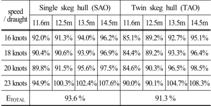
These days, main engine tuning at part load or low load has been applied by many ship owners considering slow steaming and their own operating profile. In case hull form is optimized based on operating profile and additionally main engine tuning at part or low load is applied, more energy saving could be expected.
As for main engine tuning at part load, the proportions of ETOTAL for single and twin skeg hulls compared to Ship SA and Ship TA are 94.5 % and 92.2 %. In case of main engine tuning at low load, the proportions of ETOTAL for single and twin skeg hulls
are saved more as Table 20. Therefore, main engine tuning at low load is suitable for applied operating profile.
speed
/ draught Single skeg hull (SAO) Twin skeg hull (TAO) 11.6m 12.5m 13.5m 14.5m 11.6m 12.5m 13.5m 14.5m 16 knots 94.7% 94.0% 96.7% 99.0% 87.7% 91.9% 95.5% 98.0%
18 knots 93.2% 93.4% 96.8% 99.9% 87.0% 92.0% 96.2% 99.4%
20 knots 92.6% 94.3% 98.6% 100.6% 87.3% 93.1% 99.6% 101.6%
23 knots 94.9% 99.7% 101.6% 106.6% 89.9% 99.3% 103.9% 107.3%
ETOTAL 95.9 % 93.5 %
Table 19. Comparison of for optimized hull forms based on operating profile
speed / draught
Single skeg hull (SAO) Twin skeg hull (TAO) 11.6m 12.5m 13.5m 14.5m 11.6m 12.5m 13.5m 14.5m 16 knots 92.0% 91.3% 94.0% 96.2% 85.1% 89.2% 92.7% 95.1%
18 knots 90.4% 90.6% 93.9% 96.9% 84.4% 89.2% 93.3% 96.4%
20 knots 89.8% 91.5% 95.6% 97.5% 84.6% 90.3% 96.5% 98.5%
23 knots 94.9% 100.3% 102.4% 107.6% 90.0% 90.1% 104.7% 108.3%
ETOTAL 93.6 % 91.3 %
Table 20. Comparison of for main engine tuning at low load
Performance information with trim of a container ship may help ship officers to set trim draught with better performance by loading containers properly and finally reduce fuel oil consumption further.
In addition to hull form optimization based on operating profile, as for single skeg hulls (Ship SA and SAO), performance with trim was investigated at 12.5m draught and 18 knots speed which have the highest frequency in Table 18. Trim conditions for CFD calculation are even and stern trim draughts expected under real operation for Ship SAO by CFD as shown in Table 21.
Draught /
speed Trim* EHP
(Ship SA) EHP
(Ship SAO) Comment
12.5m / 18 knots
-2 m 104.7 % 94.3 % -10.4 %
-1 m 103.1 % 93.2 % -9.9 %
Even keel 100.0 % 92.9 % -7.1 %
* Trim definition: TF-TA (Stern: -, Head: +) Table 21. Comparison of performance with trim
EHP difference for Ship SA between even keel and -2 trim by stern is 4.7 %, but as for Ship SAO, the difference is only 1.4 %, which means that Ship SAO is affected much less for trim change and has much better performance than Ship SA for trim conditions.
And also, as for Ship SAO, the calculation results implies that ship officers don’t have to take much time and work to adjust loading plan and load containers to trim draught with better performance.
Therefore, optimized hull form based on operating profile (Ship SAO) has much superior performance based on operating profile and trim conditions expected under real operation.
8. Conclusion
Initial design procedure with economic assessment and hull form optimization that can make a container ship more competitively has been described in the present work.
Through the investigation on ships which have large dimension and relatively wide breadth, both single and twin skeg container ships were designed and compared for their own characteristics.
Twin skeg container ship has better maneuverability, redundancy and less vibration because of two individual machinery plants.
However, twin skeg container ship needs higher initial investment with a little less DWT and it is even impossible to arrange machineries and equipments for small size of container ship. The required power of single skeg container ships was expected to be similar to that of twin skeg container ship at design speed, 23 knots.
Hull form optimization for both types of container ship has been conducted to improve resistance and propulsive performance at design draught and speed with several variation methods.
As for single skeg hull, The area, height and length of bulbous bow was varied to find the shape of bulbous bow to show the best resistance performance. And also, optimization of stern hull form was conducted to improve both resistance and propulsive performances. For twin skeg hull, hull form optimization was carried out for LCB position, vertical angle of skeg, distance between skegs.
Based on initially predicted operating profile for ULCS, hull form was optimized for both type of container ships and total energy was saved significantly when comparing with optimized hull form at design draught and speed. In addition, resistance performance with trim conditions was compared in view of real operation at port and sea.
All hull form optimization with variation methods of hull was
conducted extensively through flow simulation, investigation and performance assessment from CFD calculation. The model tests for both optimized hull forms were carried out to get the data and confirm the results of hull form optimization.
In addition, real time data and automated data analysis with guidance on ship draught, speed, trim, fuel oil consumption, sea conditions, wave direction, loading state, etc. are getting important to find the efficient operation to reduce fuel consumption and flight days further and make container ship smarter in another viewpoint.
References
[1] Carlton, J. S.(2007), Marine Propellers and Propulsion, Elsevier butterworth-Heinemann, http://www.sciencedirect.com/
(Search date: 2015. 10. 29.).
[2] Choi, J. S., Lee, S. D., Lee, K. W., Chun, K. W. and Nam, Y. W(2013), Real Time Measurement of Exhaust Emmisions from Main Engine using Training Ship, Journal of the Korean Society of Marine Environment & Safety, Vol. 19, No. 5, pp.
531-537.
[3] Choi, B. R., Park, C. H. and Im, N. K(2015), A Study on the Improvement of SEEMP of Shipping Companies, Journal of the Korean Society of Marine Environment & Safety, Vol. 21, No. 2, pp. 147-153.
[4] Hollenbach, U. and O. Reinholz(2010), Hydrodynamic Trends in Performance Optimization, 11th International Symposiumon the Practical Design of Ship sand Other Flation Structures, Riode Janeiro, Brazil, http://www.gbv.de/(Search date: 2015.
10. 29.).
[5] ITTC(1978), Report of Performance Committee, 15th ITTC, Hague, pp. 359-392.
[6] Kim, J., I. R. Park, K. S. Kim, S. H. Van and Y. C.
Kim(2011), Development of a Numerical Method of the Evaluation of Ship Resistance and Self-Propulsion Performance, Journal of the Society of Naval Architects of Korea, April 2011, Vol. 48, No. 2, SNAK.2011.48.2.147, pp. 147-157.
[7] Park, D. W., M. G. Kim, S. H. Chung and Y. K.
Chung(2007), Stern flow analysis and design practice for the improvement of self-propulsion performance of twin-skeg ships, PRADS 2007, Houston, vol. 2, pp. 981-988.
[8] Resolution MEPC. 203(62)(2011), Amendments to the Annex of the Protocol of 1997 to Amend the International Convention for the Prevention Pollution from Ship, 1973, as
Modified by the Protocol of 1978 Relation Thereto, http://cil.nus.edu.sg/(Search date: 2015. 10. 29.).
Received : 2015. 09. 16.
Revised : 2015. 10. 08.
Accepted : 2015. 10. 27.