수소이온 전도성 가교된 P(VDF-co-CTFE)-MAA/SEMA 막 제조 및 분석
라즈쿠마 파텔⋅증 효 뢰⋅허 성 연⋅김 종 학† 연세대학교 화공생명공학과
(2013년 8월 8일 접수, 2013년 8월 26일 수정, 2013년 8월 26일 채택)
Preparation and Characterization of Proton Conducting Crosslinked P(VDF-co-CTFE)-MAA/SEMA membranes
Rajkumar Patel, Zeng Xiao Lei, Sung Yeon Heo, and Jong Hak Kim†
Department of Chemical and Biomolecular Engineering, Yonsei University, Seoul 120-749, Korea (Received August 8, 2013, Revised August 26, 2013, Accepted August 26, 2013)
요 약: 촉매 1,8-diazabicyclo[5,4,0]undec-7-ene(DBU)를 이용하여, poly(vinylidenefluoride-co-chlorotrifluoroethylene) P(VDF-co-CTFE) 고분자와 methacrylic acid (MAA)를 반응시켜, P(VDF-co-CTFE)-MAA 공중합체를 제조하였다. 또한 P(VDF-co-CTFE)-MAA와 2-sulfoethyl methacrylate (SEMA) 단량체를 4’,4’-azobis(4-cyanovaleric acid) (ACVA) 개시제 하에 서 자유 라디칼 중합하여 수소 이온 전도성 막을 제조하였다. SEMA 함량이 많아짐에 따라 술폰산 그룹이 증가하였다.
SEMA 함량이 50%일 때 최대 이온교환 용량값이 0.82 meq/g에 도달하였으며 이는 함수량 결과와 일치하였다. 또한, SEMA 함량이 50%일 때 수소이온 전도도가 0.041 S/cm까지 도달하였다. 이러한 결과는 분리막에서 SEMA 함량이 증가할수록 수소 이온을 전달시킬 수 있는 이온그룹이 증가하기 때문이다.
Abstract: Poly(vinylidenefluoride-co-chlorotrifluoroethylene) P(VDF-co-CTFE) polymer was attached to methacrylic acid (MAA) in the presence of 1,8-diazabicyclo[5,4,0]undec-7-ene(DBU) catalyst to prepare P(VDF-co-CTFE)-MAA copolymer.
The modified P(VDF-co-CTFE)-MAA was polymerized with 2-sulfoethyl methacrylate (SEMA) monomer in the presence of 4’,4’-azobis(4-cyanovaleric acid(ACVA) initiator by free radical polymerization to form the proton conducting membrane.
The ratio of the SEMA was increased in the membrane to increase the presence of the acidic group. The maximum IEC value that was observed at 50% SEMA was around 0.82 meq/g, which is consistentwith the water uptake value. The highest proton conductivity achieved by P(VDF-co-CTFE)-MAA/SEMA membrane with 50% SEMA was approximately 0.041 S/cm.
This indicates that the available ionic group for the proton conduction increases with the increase in the SEMA in the membrane.
Keywords: polymer electrolyte membrane, crosslinking, proton conductivity, fuel cell
1. Introduction
1)
The incorporation of metal salt in the polymer ma- trix or polymer backbone linked covalently is usually known as polymer electrolytes. Due to the excellent electrochemical properties, solid polymer electrolytes have recently been of technological interest for the
†교신저자(e-mail: [email protected])
possible applications to energy conversion units such as batteries, fuel cells, solar cells, electrochromic dis- play devices and facilitated transport membranes[1-4].
Specially proton conducting polymer electrolytes, which have negatively charged groups attached to the poly- mer backbone, are extensively used in the fuel cell ap- plications such as polymer electrolyte membrane fuel cells (PEMFC) or direct methanol fuel cells (DMFC) [5-8].
Many investigations have been carried out on proton conducting polymer electrolyte membranes for the ap- plications to fuel cells over the last decade[9-12]. The easier transportation of proton ions is very important for fuel cell applications. Thus, proton conducting pol- ymer electrolyte membranes usually contain pendant cation exchange sites such as sulfonic acids (SO3-
).
The most commonly used proton conducting polymer electrolyte membranes in fuel cells applications are DuPont’s Nafion® membranes consistingof a hydro- phobic fluorocarbon backbone and hydrophilic sulfonic pendant side chains. These structures produce a micro- phase-separated morphology of membranes and thus they exhibit excellent thermal, mechanical and electro- chemical properties. However these membranes have the following demerits such as high cost, high cost per unit power, high methanol crossover and reduced pro- ton conductivity at high temperature/low humidity con- ditions. Thus many efforts have been made to the de- velopment of alternative polymer electrolytes to per- fluorinated membranes[13-21].
In this work, a novel proton conducting membrane consisting of poly(vinylidenefluoride-co-chlorotrifluoro- ethylene) P(VDF-co-CTFE), methacrylic acid (MAA) and 2-sulfoethyl methacrylate (SEMA) is prepared. The P(VDF-co-CTFE)-MAA/SEMA membranes were devel- oped by linking the P(VDF-co-CTFE) with MAA mon- omer and in turn polymerizing with SEMA by free radical polymerization. The resulting membrane was characterized by Fourier transform infrared (FTIR) spec- troscopy to check the successful polymerization. The electrochemical properties like ion exchange capacity (IEC), water uptake and proton conductivity were re- ported.
2. Experimental
2.1. Materials
Poly(vinylidenefluoride-co-chlorotrifluoroethylene) (P(VDF-co-CTFE)) was provided from Solvey chemicals.
Methacrylic acid (MAA), 1,8-diazabicyclo[5,4,0]undec- 7-ene(DBU), 2-sulfoethyl methacrylate (SEMA), 4’,4’-
azobis(4-cyanovaleric acid(ACVA) and N-methyl-2- pyrrolidone (NMP) are procured from Aldrich chemicals.
2.2. Synthesis of P(VDF-co-CTFE)-MAA In a 250 mL round flask, 4.0 g P(VDF-co-CTFE) was dissolved in 30 ml NMP at 80°C. When the pow- ders were dissolved completely, the temperature of the reaction flask was lowered to room temperature. And then, 4 mL MAA was added into the solution. After preparing homogeneous solution, 4.0 mL DBU was added into the reaction flask and the colorless reaction solution became black. The reaction flask was sealed with a rubber septum and pure nitrogen was purged for 30 minutes. The flask was immersed in an oil bath at 50°C and the reaction was allowed to proceed for 6 h. After reaction, the resultant polymer was pre- cipitated into a large amount of methanol for 2 times.
The aquatic layer was removed and a dark brown liq- uid was obtained. Finally, the polymer was collected bycentrifugation and dried in an oven overnight at 50°C.
2.3. Preparation of P(VDF-co-CTFE)-MAA/SEMA Membranes
To prepare the P(VDF-co-CTFE)-MAA/SEMA mem- brane, a different amount of P(VDF-co-CTFE)-MAA was dissolved in 3 mL NMP, and then the different amount of SEMA was added with stirring, followed by 0.015 g ACVA. The detailed composition of each component is presented in Table 1. The mixture was stirred for 1 day and poured into a glass dish. Finally, the dish was put into an oven at 80°C for 24 h and the solution became a membrane. Pouring some water into the glass to peel the membrane off and a light brown membrane was obtained. The prepared mem- branes were stored in water until ready to be used.
2.4. Ion Exchange Capacity (IEC)
IEC of the membranes was measured by the classi- cal titration method. The membranes were soaked in 1.0 M NaCl solution for 24 h before measuring IEC.
The protons released due to the exchange reaction with
F F
H
Hm F F
F
Cln O
HO
F F
H
H F F
F
O CH3
O CH3
m
n HCl
MAA
500C/6h
P(VDF-co-CTFE)
DBU
P(VDF-co-CTFE)-MAA Scheme 1. Synthesis of P(VDF-co-CTFE)-MAA copolymer.
4000 3500 3000 2500 2000 1500 1000 1151 1203 1761 1178
1693 1645
1635
P(VDF-co-CTFE) P(VDF-co-CTFE)-MAA
1691
Absorbance
Wavenumber (cm-1)
MAA
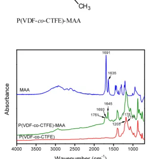
Fig. 1. FT-IR spectra of pristine P(VDF-co-CTFE), pris- tine MAA and P(VDF-co-CTFE)-MAA copolymer.
Na ions were titrated against 0.01 M standardized NaOH solution, using phenolphthalein indicator. The experimental IEC of the membranes was calculated us- ing the following equation.
(polymer) Weight
N (mEq/g) X
IEC = × NaOH
(1)
where X is the volume of NaOH consumed and NNaOH is the normality of NaOH.
2.5. Water Uptake
Water uptake was determined by weighing vacuum dried membrane and fully equilibrated membrane with water. The surface of the membrane sample was quick- ly wiped with an absorbent paper to remove the excess of water adhering to it and the sample was then weighed. The water uptake of the membrane was de- termined from
W 100 W - (wt%) W uptake water
d d
w ×
= (2)
where Ww and Wd are the weights of wet and dried membranes, respectively.
2.6. Proton Conductivity
A four-point probe method was used to measure the proton conductivity of the membranes using homemade conductivity cell. Before the measurement of proton conductivity, the prepared membranes were equilibrated
with deionized water. Complex impedance measure- ments were carried out in the frequency range 1 Hz-8 MHz at 25°C, using a ZAHNER IM-6 impedance analyzer. The impedance spectra of the membranes can be used to generate Nyquist plots, and the proton con- ductivity was calculated from the plots[21,22].
2.7. FT-IR Measurement
FT-IR spectra were recorded Excalibur Series FTIR (DIGLAB Co.) instrument between the frequency range of 4,000 to 400 cm-1 using ATR facility.
3. Results and Discussion
The synthesis process of P(VDF-co-CTFE)-MAA co- polymer is presented in Scheme 1 The chlorine linked to the P(VDF-co-CTFE) is attached to the carboxylic group by condensation reactionin the presence of DBU
P(VDF-co-CTFE)-MAA
SEMA O S O
O O
HO
F
F H
H F
F F
O O
m
n
F
F H
H F
F F
O O
m
n
ACVA
O
O S
O
O OH
X
F F
H H
F F
F O O
m n
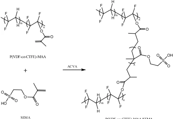
P(VDF-co-CTFE)-MAA/SEMA Scheme 2. Preparation of P(VDF-co-CTFE)-MAA/SEMA membranes.
SEMA wt% P(VDF-co-CTFE)-MAA (g) SEMA (g) ACVA (g) NMP (mL)
10% 0.27 0.03 0.015 3.0
20% 0.24 0.06 0.015 3.0
30% 0.21 0.09 0.015 3.0
40% 0.18 0.12 0.015 3.0
50% 0.15 0.15 0.015 3.0
Table 1. Composition for the Preparation of P(VDF-co-CTFE)-MAA/SEMA Membranes catalyst to form an ester link. Fig. 1 shows the FTIR
spectra of pristine P(VDF-co-CTFE), pristine MAA and P(VDF-co-CTFE)-MAA copolymer. The pristine P(VDF- co-CTFE) exhibited strong absorption band at around 1,203, 1,178, and 1,151 cm-1, which are attributed to the crystalline chains of P(VDF-co-CTFE). After the formation of the ester linkage in P(VDF-co-CTFE)- MAA, the new absorption bands are observed at 1,693, 1,645 cm-1 due to the carbonyl group (C = O) and the C = C double bond of the MAA.
The preparation scheme of P(VDF-co-CTFE)-MAA/
SEMA membranes is presented in Scheme 2 The prep-
aration composition of the P(VDF-co-CTFE)-MAA/
SEMA membrane is presented in Table 1 Because the membranes with SEMA content above 50% showed poor mechanical properties, the membranes with 0~ 50% of SEMA were prepared and characterized. The acrylic monomer of the P(VDF-co-CTFE)-MAA poly- merized with the acrylic monomer of SEMA by free radical polymerization in the presence of thefree radi- cal initiators ACVA. The successfulpolymerization was confirmed by FTIR study. Fig. 2 represents the FT-IR spectra of P(VDF-co-CTFE)-MAA, pristine SEMA and the composite membranes with different ratio of
4000 3500 3000 2500 2000 1500 1000
1720
P(VDF-co-CTFE)-MAA/SEMA(50%) P(VDF-co-CTFE)-MAA/SEMA(40%) P(VDF-co-CTFE)-MAA/SEMA(30%) P(VDF-co-CTFE)-MAA/SEMA(20%) P(VDF-co-CTFE)-MAA/SEMA(10%)
1678
1037 1041 1014 1631
1693 1716
Absorbance
Wavenumber (cm-1)
1647 SEMA
P(VDF-co-CTFE)-MAA
Fig. 2. FT-IR spectra of pristine SEMA, P(VDF-co-CTFE)- MAA copolymer and the P(VDF-co-CTFE)-MAA/ SEMA membranes with different ratios of SEMA.
10 20 30 40 50
0.0 0.2 0.4 0.6 0.8 1.0
IEC (mequiv/g)
SEMA (wt%)
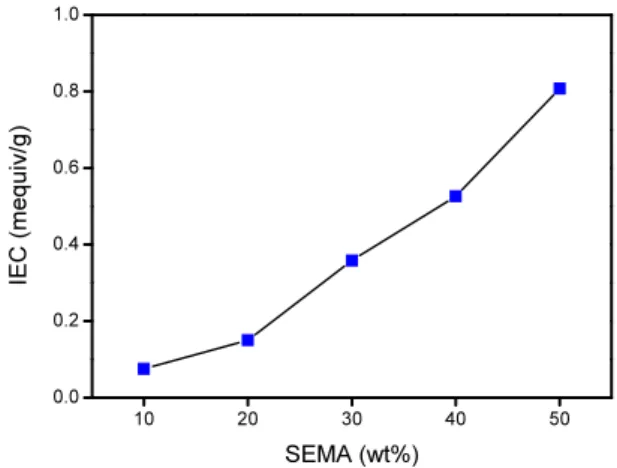
Fig. 3. IEC values of P(VDF-co-CTFE)-MAA/SEMA mem- branes with different ratios of SEMA.
10 20 30 40 50
20 30 40 50 60 70 80
Water Uptake (%)
SEMA(wt%)
Fig. 4. Water uptake of P(VDF-co-CTFE)-MAA/SEMA membranes with different ratios of SEMA.
SEMA. The absorption bands at 1,631 cm-1 and 1,678 cm-1 of the SEMA, 1,647 cm-1 and 1,693 cm-1 of the P(VDF-co-CTFE)-MAA attributed to the C = C double bond disappeared after reaction indicates the successful polymerization between SEMA and P(VDF-co-CTFE)- MAA in the presence of ACVA free radical initiators.
In addition, with the increase of SEMA amount, the peak at ~1,040 cm-1 attributed to O = S = O group became stronger. This implied that the incorporation of the SEMA group increase with the increase in the amount of the SEMA monomer.
Fig. 3 shows the IEC values of the P(VDF-co-CTFE)- MAA/SEMA membranes as a function of SEMA con- centration. By increasing the amount of the SEMA in
the P(VDF-co-CTFE)-MAA/SEMA membranesfrom 10 to 50 wt% the IEC value increased from 0.07 to 0.82 meq/g due to the increased in the charged group in the membrane. At 50 wt% of SEMA group in the mem- brane, it exhibited 0.82 meq/g of IEC value which is close to the IEC value of Nafion 117. The higher val- ue of IEC of the P(VDF-co-CTFE)-MAA/SEMA mem- brane indicates the presence of large amount of sul- fonic group inthe membrane.
The water uptake of the P(VDF-co-CTFE)-MAA/SEMA membrane with different amount of SEMA is repre- sented in Fig. 4 The water uptake value at 10 wt% of SEMA is around 21%. The water uptake increased al- most linearly with increase in SEMA concentration up to 50% SEMA with a value of 79%. The water uptake is consistent with the IEC value as presented in Fig. 3 This is mainly due to the fact that water uptake is lin- early proportional to the concentration of ionic SO3-
groups, i.e. IEC value.
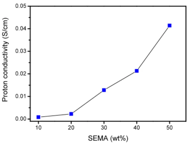
The proton conductivities of the P(VDF-co-CTFE)- MAA/SEMA membrane at room temperature as a function of the concentration of SEMA is presented in Fig. 5 The proton conductivities are mostly dependent on the presence of the SEMA or acidic SO3-
group as presented in Fig. 5 The conductivity was around 0.0024 S/cm at concentration of 20 wt% SEMA. The maximum proton conductivity achieved was around 0.0414 S/cm for SEMA concentration of 50%. The
10 20 30 40 50 0.00
0.01 0.02 0.03 0.04 0.05
Proton conductivity (S/cm)
SEMA (wt%)
Fig. 5. Proton conductivity of P(VDF-co-CTFE)-MAA/
SEMA membranes with different ratios of SEMA.
tendency of the increase in the proton conductivity is similar to the IEC value as presented in Fig. 3, which is due to the increase in the acidic SO3- group avail- ability in P(VDF-co-CTFE)-MAA/SEMA membrane.
4. Conclusion
The hydrophobic, mechanically and thermally strong polymer, P(VDF-co-CTFE) was covalently linked to the acrylic monomer MAA through the functional chlorine group in the presence of DBU catalyst. Then P(VDF-co-CTFE)-MAA polymer was converted to pro- ton conducting P(VDF-co-CTFE)-MAA/SEMA polymer electrolyte membrane via linking to SEMA through MAA by free radical polymerizationreaction in the presence of ACVA initiator. TheIEC value increased continuously with the increase in the SEMA concen- tration in the membrane. The maximum IEC value was 0.82 meq/g at 50% SEMA, which well correlates with the water uptake results. The highest proton con- ductivity of P(VDF-co-CTFE)-MAA/SEMA membrane was 0.041 S/cm at 50% SEMA.
Acknowledgement
This work has been supported by the Core Research Program (2012R1A2A2A02011268) and the Low Obser- vable Technology Research Center program of Defense
Acquisition Program Administration and Agency for Defense Development.
References
1. P. E. Trapa, B. Huang, Y.-Y. Won, D. R. Sadoway, and A. M. Mayes, “Block Copolymer Electrolytes Synthesized by Atom Transfer Radical Polymeriza- tion for Solid-State, Thin-Film Lithium Batteries, Electrochem”, Solid-State Letters, 5, A85 (2002).
2. J. H. Kim, M. S. Kang, Y. J. Kim, J. Won, N. G.
Park, and Y. S. Kang, “Dye-Sensitized Nanocrys- talline Solar Cells Based on Composite Polymer Electrolytes Containing Fumed Silica Nanopar- ticles”, Chem. Commun., 14, 1662 (2004).
3. S. W. Kuo, C. H. Wu, and F. C. Chang, “Thermal Properties, Interactions, Morphologies, and Conduc- tivity Behavior in Blends of Poly(vinylpyridine)s and Zinc Perchlorate”, Macromolecules, 37, 192 (2004).
4. J. H. Kim, B. R. Min, J. Won, S. H. Joo, H. S.
Kim, and Y. S. Kang, “Role of Polymer Matrix in Polymer/Silver Complexes for Structure, Interactions, and Facilitated Olefin Transport”, Macromolecules, 36, 6183 (2003).
5. J.-H. Choi, P.-H. Kang, Y.-M. Lim, J.-Y. Sohn, J.-H. Shin, C.-H. Jung, J.-P. Jeun, and Y.-C. Nho,
“Preparation and Characterization of Poly(styr- enesulfonic acid)-grafted Fluoropolymer Membrane for Direct Methanol Fuel Cell”, Korean Membrane Journal, 9, 52 (2007).
6. L. Depre, M. Ingram, C. Poinsignon, and M.
Popall, “Proton conducting sulfon/sulfonamide func- tionalized materials based on inorganic–organic matrices”, Electrochim. Acta, 45, 1377 (2000).
7. S. D. Mikhailenko, K. Wang, S. Kaliaguine, P.
Xing, G. P. Robertson, and M. D. Guiver, “Proton conducting membranes based on cross-linked sulfo- nated poly(ether ether ketone) (SPEEK)”, J. Membr.
Sci., 233, 93 (2004).
8. C. H. Park, C. H. Lee, Y. S. Chung, and Y. M.
Lee, “Preparation and Characterization of Cross- linked Block and Random Sulfonated Polyimide Membranes for Fuel Cell”, Membrane Journal, 16, 241 (2006).
9. D. J. Kim, B.-J. Chang, C. K. Shin, J.-H. Kim, S.-B. Lee, and H.-J. Joo, “Preparation and Charac- terization of Fluorenyl Polymer Electrolyte Mem- branes Containing PFCB Groups”, Membrane Journal, 16, 16 (2006).
10. S.-L. Chen, J. B. Benziger, A. B. Bocarsly, and T.
Zhang, “Photo-Cross-Linking of Sulfonated Styrene- Ethylene-Butylene Copolymer Membranes for Fuel Cells”, Ind. Eng. Chem. Res., 44, 7701 (2005).
11. J. R. Varcoe, R. C. T. Slade, E. L. H. Yee, S. D.
Poynton, D. J. Driscoll, and D. C. Apperley, “Poly (ethylene-co-tetrafluoroethylene)-Derived Radiation- Grafted Anion-Exchange Membrane with Properties Specifically Tailored for Application in Metal-Cation- Free Alkaline Polymer Electrolyte Fuel Cells.”, Chem. Mater., 19, 2686 (2007).
12. Z. Li, J. Ding, G. P. Robertson, and M. D. Guiver,
“A Novel Bisphenol Monomer with Grafting Capa- bility and the Resulting Poly(arylene ether sulfone)s”, Macromolecules, 39, 6990 (2006).
13. C. Manea and M. Mulder, “Characterization of polymer blends of polyethersulfone/sulfonated poly- sulfone and polyethersulfone/sulfonated polyethere- therketone for direct methanol fuel cell applica- tions”, J. Membr. Sci., 206, 443 (2002).
14. J. H. Choi, C. K. Yeom, J. M. Lee, and D. S.
Suh, “Nanofiltration of Electrolytes with Charged Composite Membranes”, Membrane Journal, 13, 29 (2003).
15. C. Heitner-Wirguin, “Recent advances in perfluo- rinated ionomer membranes: structure, properties and applications”, J. Membr. Sci., 120, 1 (1996).
16. D. K. Lee, Y. W. Kim, J. K. Choi, B. R. Min,
and J. H. Kim, “Preparation and Characterization of Proton Conducting Crosslinked Diblock Copoly- mer Membranes”, J. Appl. Polym. Sci., 107, 819 (2008).
17. Y. W. Kim, J. K. Choi, J. T. Park, and J. H. Kim,
“Proton Conducting Poly(vinylidene fluoride-co-chlo- rotrifluoroethylene) Graft Copolymer Electrolyte Membranes”, J. Membr. Sci., 313, 315 (2008).
18. Z. Wang, H. Ni, C. Zhao, X. Li, T. Fu, and H.
Na, “Investigation of sulfonated poly(ether ether ke- tone sulfone)/heteropolyacid composite membranes for high temperature fuel cell applications”, J. Polym.
Sci. B: Polym. Phys., 44, 1967 (2006).
19. T. Z. Fu, C. J. Zhao, S. L. Zhong, G. Zhang, K.
Shao, H. Q. Zhang, J. Wang, and H. Na, “SPEEK/
epoxy resin composite membranes in situ polymer- ization for direct methanol fell cell usages”, J.
Power Sources, 165, 708 (2007).
20. Y. S. Kim, F. Wang, M. Hickner, T. A.
Zawodzinski, and J. E. McGrath, “Fabrication and characterization of heteropolyacid (H3PW12O40)/ di- rectly polymerized sulfonated poly(arylene ether sulfone) copolymer composite membranes for high- er temperature fuel cell applications”, J. Membr.
Sci., 212, 263 (2003).
21. J. K. Choi, D. K. Lee, Y. W. Kim, B. R. Min, and J. H. Kim, “Composite Polymer Electrolyte Membranes Comprising Triblock Copolymer and Heteropolyacid for Fuel Cell Applications”, J.
Polym. Sci. B. Polym. Phys., 46, 691 (2008).
22. J. T. Park, K. J. Lee, M. S. Kang, Y. S. Kang, and J. H. Kim, “Nanocomposite Polymer Electrolytes Containing Silica Nanoparticles: Comparison be- tween Poly(ethylene glycol) and Poly(ethylene ox- ide) dimethyl ether”, J. Appl. Polym. Sci., 106, 4083 (2007).