용접시편의 테두리 모양이 응력 분포에 미치는 영향
양승용†· 구병춘
*
Effect of the boundary shape of weld specimen on the stress distribution
Seung-Yong Yang and Byeongchoon Goo
Key Words :
Boundary shape (테두리 모양), Weld specimen (용접시편), Finite element method (유한 요소법)Abstract
In finite element analysis of mechanical behavior of weld, typical process is first to obtain a finite element model containing residual stress by conducting welding analysis and then to examine the computational specimen for various external loading. The numerical specimen with residual stress has irregular boundary lines since one usually begins the welding analysis from a body having regular straight boundary lines and large thermal contraction takes place during cooling of weld metal. We notice that these numerical weld specimens are different from the real weld specimens as the real specimens are usually cut from a bigger weld part and consequently have straight boundaries neglecting elastic relaxation associated with the cutting. In this paper, an iterative finite element method is described to obtain a weld specimen which is bounded by straight lines. The stress distributions of two types of weld specimen, one with regular and the other with irregular boundaries, are compared to check the effect of the boundary shape. Results show that the stress distribution can be different when large plastic deformation is induced by the application of external loading. In case of elastic small deformation, the difference turns out almost negligible.
1. 서 론
기호설명
ℵ
n: initial configuration of n -th iteration
Fig. 1 은 유한요소법을 이용하여 용접공정을 해 석할 경우 얻게 되는 용접시편의 용접공정 전 후 의 유한요소 격자를 보여준다. 그림에서 볼 수 있 듯이 용접시편의 유한요소 모델은 용접공정 전에 는 직사각형이며 용접과정 동안 일어나는 열변형 에 의해 용접공정 후에는 초기의 직사각형에서 벗 어난 변형된 형태를 가지게 된다. 이렇게 얻어진 용접시편에 외력를 가함으로써 응력 및 변형률의 변화를 관찰하는 것이 전형적인 용접시편의 기계 적 거동 해석 방법이다
(1). 그러나 실제 용접시편은 커다란 용접부재를 절단하여 얻어지게 되며, 따라 서 그 외곽선은 직선이고 전체적인 형태도 직사각 형 모양을 띠게 된다. 이러한 점을 고려할 때 용 접공정의 유한요소해석으로부터 얻어지는 용접시 편은 실제 용접시편과 다른 형태임을 알 수 있다.
본 논문에서는 외곽선이 직선이 아닌 (“비정규적”
ℜ
n: deformed configuration of n -th iteration
ℜ
*: object configuration
x
i: position vector of i -th node in deformed mesh
X
i: position vector of i -th node in object mesh
i
i
X
x − : distance between two points
†
한국철도기술연구원 E-mail : [email protected]
TEL : (031) 460-5115 FAX : (031) 460-5289
* 한국철도기술연구원
으로 정의) 용접시편과 외곽선이 직선인 (“정규 적”으로 정의) 용접시편의 기계적 거동에 있어서 의 차이에 대해 연구하였다. 우선 정규적인 용접 시편을 얻기 위해 반복적인 유한요소해석을 수행 하였으며, 이렇게 얻어진 정규적인 용접시편에 외 력이 작용할 경우 그 내부의 응력분포를 관찰함으 로써 비정규적인 용접시편과의 차이점에 대해 조 사하였다.
Fig. 1 Initial mesh (top) and deformed mesh (down) of welding analysis. The deformation is magnified 10 times.
2. 반복적인 유한요소 계산법
Fig. 1 에서 확인할 수 있듯이, 유한요소 모델의 초기 형태가 직사각형일 경우 용접공정 이후의 용 접시편은 불규칙한 모양을 가지게 된다. 따라서 직선 테두리 선을 가지는 직사각형의 용접시편을 얻기 위해서는 초기 유한요소 모델이 직사각형이 아니어야 할 것이다. 본 논문에서는 반복적인 유 한요소계산을 이용하여 용접공정 이후의 용접시편 이 정규적인 모양이 되는 초기 요한요소 모델을 유도하였다. 즉, 얻고자 하는 직사각형 정규 시편 의 모양을 라 정의할 때, n 번째 반복계산 후 의 용접시편의 모양 과 사이의 차이가 정 해진 오차 이내에 들도록 용접공정 이전의 유한요 소 모델 을 다음의 방법을 이용하여 구하였다.
ℜ
*n
ℜ
nℜ
*ℵ
(
*1
= ℵ − ℜ − ℜ
ℵ
n+ n n) (1) 위 식에서 마이너스 연산의 의미는 영역을 정의하 는 유한요소 격자의 위치벡터에 대한 연산을 의미 한다. 즉 각각의 유한요소 격자점에서 원하는 위
치 ( ℜ )와 현 위치 ( ℜ ) 사이의 차이 만큼을 에 더해줌으로써 다음 단계의 유한요소 격자 의 위치 ( ℵ )를 얻는 방식이다. 한편 과
은 용접공정으로 서로 연결되어 있다. 즉,
*
n
ℵ
nℜ
n+1
n
ℵ
n→
ℵ
n{용접공정에 의한 열변형} → ℜ
n초기조건 의 값은 얻고자 하는 직사각형 유한 요소 모델로 정의하였다.
ℵ
0* 0
= ℜ ℵ
수렴 판정 기준은 각 유한요소 절점의 위치와 목 적하는 위치 사이의 거리의 합(norm)이 어느 한도 이내에 들어오면 더 이상 식 (1)에 의해 초기 유 한요소 모델을 수정하지 않는 것으로 하였다.
∑
=−
= ℜ
− ℜ
=
Ni
i i n
1
norm
*x X
where x
i∈ ℜ
n, X
i∈ ℜ
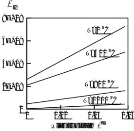
*Fig. 3 은 Fig. 1 과 같은 2 차원 직사각형 용접시 편에 대하여, n=0, 1, 2 에서의 용접시편 절점의 위 치와 직사각형 시편 절점의 위치 사이의 거리를 나타낸 것이다. 반복계산 횟수 n 이 증가함에 따 라 용접시편의 형태는 직사각형에 가까워 짐을 볼 수 있다. 한편 용접공정은 2 개의 100mm x 25mm 시편을 10mm 용접비드를 이용하여 맞대기 용접 하는 경우로서 대칭조건을 이용하여 시편의 반만 을 해석하였다. (Fig. 1 참조) 용접해석의 방법 및 해석에 사용된 물성치는 참고문헌 (2)에 기술되어 있다. Fig. 2 는 해석에 사용된 용접시편의 온도별 항복응력을 나타낸다.
0 0.02 0.04 0.06
Plastic strain ε
pl0
2E+08 4E+08 6E+08 8E+08
T=1200
oC
σ
yT=0
oC
T=800
oC T=400
oC
Fig. 2 Stress vs. strain curves at several temperatures.
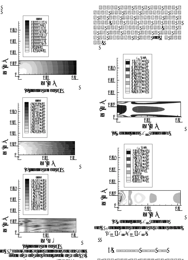
용접공정에 사용된 변형 전 시편의 형태가 직 사각형일 경우와 반복적인 유한요소해석을 이용하 여 구한 형태일 경우의 용접잔류응력의 분포를 조 사하였다. 열응력 해석에 사용된 온도 분포는 두 경우에 대하여 동일하다고 가정하였다. 열응력 해 석 결과 나타난 잔류응력 분포는 두 경우에 대하 여 거의 동일하였으며 그 분포를 Fig. 4 에 나타내 었다.
X (m)
Y( m )
0 0.05 0.1
0 0.02 0.04 0.06 0.08
error 0.000544167 0.000487735 0.000431303 0.000374871 0.000318439 0.000262006 0.000205574 0.000149142 9.271E-05 3.62778E-05
X (m)
Y( m )
0 0.05 0.1
0 0.02 0.04 0.06 0.08
σ11(Pa) 1.45464E+07 4.15913E+06 -6.22811E+06 -1.66153E+07 -2.70026E+07 -3.73898E+07 -4.77771E+07 -5.81643E+07 -6.85515E+07 -7.89388E+07
(a) Iteration number n=0
X (m)
Y( m )
0 0.05 0.1
0 0.02 0.04 0.06 0.08
error 9.78182E-06 8.80364E-06 7.82545E-06 6.84727E-06 5.86909E-06 4.89091E-06 3.91273E-06 2.93455E-06 1.95636E-06 9.78182E-07
(a) Residual stress σ
xxdistribution.
X (m)
Y( m )
0 0.05 0.1
0 0.02 0.04 0.06 0.08
σ22(Pa) 1.07582E+07 9.25157E+06 7.74496E+06 6.23835E+06 4.73173E+06 3.22512E+06 1.7185E+06 211891 -1.29472E+06 -2.80134E+06
(b) Iteration number n=1
X (m)
Y( m )
0 0.05 0.1
0 0.02 0.04 0.06 0.08
error 9.58865E-07 8.62978E-07 7.67092E-07 6.71205E-07 5.75319E-07 4.79432E-07 3.83546E-07 2.87659E-07 1.91773E-07 9.58865E-08
(b) Residual stress σ
yydistribution Fig. 4 Residual stress distribution by welding analysis.
( σ
11= σ
xx, σ
22= σ
yy)
(c) Iteration number n=2
3. 용접시편의 기계적 거동
Fig. 3 Contour plots of the difference between weld specimen mesh and object specimen mesh. At
each node, error is defined by x
i− X
i. 앞 절에서 유도한 직선 테두리를 갖는 용접시편
X (m)
Y( m )
0 0.05 0.1
0 0.02 0.04 0.06 0.08
σ11(Pa) -5.57337E+08 -5.84735E+08 -6.12133E+08 -6.39531E+08 -6.66929E+08 -6.94328E+08 -7.21726E+08 -7.49124E+08 -7.76522E+08 -8.0392E+08
(정규 용접시편)에 대하여 힘 또는 변위가 외력으 로 작용할 경우 그에 의한 시편 내부의 응력 분포 를 조사하였다. 만약 외력에 의한 시편의 응답이 탄성적이라면, 용접시편의 모양이 정규적이냐 비 정규적이냐에 관계없이 시편 내부의 응력 분포는 거의 일치한다는 사실이 확인되었다. 이러한 사실 로 미루어 보아 용접공정에 의한 열변형이 그다지 크지 않음을 알 수 있었다. 만약 유한요소 격자가 충분히 촘촘하여 비정규 시편에서 존재할 수 있는 용접부의 노치를 모델링 할 수 있다면 노치에서의 응력집중에 의해 응력 분포가 차이를 보일 수 있 겠으나, 현재의 유한요소 격자에 대해서는 응력의 차이가 크지 않았다. 한편 외력의 크기가 커짐에 따라 시편에는 대변형이 일어나게 되고 용접시편 의 초기 모양이 소성변형과 상호작용 하면서 시편 내부의 응력 분포에 약간의 차이를 가져오게 된다.
Fig. 5 는 용접시편의 오른쪽 경계에 1mm 의 변위 하중이 x 축(수평축) 방향으로 반복적으로 작용할 경우(R=0)에 대한 용접시편의 응력 분포를 정규 시편과 비정규 시편에 대하여 도시한 것이다. 하 중이 최대값에 도달했을 때와 최소값에 도달했을 때의 (= ) 응력 분포는 두 가지 시편에 대 하여 최대값과 최소값은 거의 일치하지만 최대값 과 최소값이 나타나는 위치가 차이를 보임을 확인 할 수 있다. 즉, Fig. 5(b) 에서 응력은 좌측 상단에 서 최대이지만 (d) 에서는 응력이 좌측 하단에서 최대임을 볼 수 있다. 이러한 결과는 용접시편 형 상이 소성변형에 의해 변형됨에 따른 결과라고 생 각된다.
σ
xxσ
11(b) Regular specimen at the minimum load
X (m)
Y( m )
0 0.05 0.1
0 0.02 0.04 0.06 0.08
σ11(Pa) 7.55402E+08 7.36631E+08 7.17861E+08 6.99091E+08 6.80321E+08 6.6155E+08 6.4278E+08 6.2401E+08 6.0524E+08 5.86469E+08
X (m)
Y( m )
0 0.05 0.1
0 0.02 0.04 0.06 0.08
σ11(Pa) 8.0673E+08 7.84116E+08 7.61503E+08 7.38889E+08 7.16275E+08 6.93661E+08 6.71047E+08 6.48433E+08 6.2582E+08 6.03206E+08
(c) Irregular specimen at the maximum load
X (m)
Y( m )
0 0.05 0.1
0 0.02 0.04 0.06 0.08
σ11(Pa) -5.35316E+08 -5.64477E+08 -5.93637E+08 -6.22798E+08 -6.51958E+08 -6.81119E+08 -7.10279E+08 -7.3944E+08 -7.686E+08 -7.97761E+08
(a) Regular specimen at the maximum load
(d) Irregular specimen at the minimum load Fig. 5 Stress distribution at the maximum and
minimum loads.
4. 결 론
본 논문에서는 용접시편의 모양이 정확히 직사 각형인 경우와 아닌 경우에 대하여 용접시편의 기 계적 거동에 대하여 살펴보았다. 먼저 직사각형 용접시편을 얻기 위하여 원하는 형상과의 반복적 인 비교를 통하여 현재의 유한요소 격자를 수정해 나가는 반복적인 유한요소 계산법을 적용하였다.
이를 통하여 얻어진 직사각형 용접시편과 직사각 형이 아닌 용접시편에 대하여 외력을 주었을 때 시편 내부의 응력 분포를 비교하였다. 외력이 충 분히 작아 시편에 탄성 변형만을 유발할 경우 두 가지 형태의 용접시편의 응력분포는 거의 동일하 였으며, 용접공정에 의한 열변형이 그다지 크지 않음을 확인할 수 있었다. 그러나 외력의 크기가 증가하여 시편에 대변형이 발생할 경우 시편의 응 력분포는 약간의 차이를 보일 수 있음을 확인하였 다. 두 시편의 이러한 응력 분포의 차이가 피로균 열 발생 및 전파에 어떠한 영향을 미치는 지에 대 해서는 향후 연구로 추진할 계획이다.
후 기
본 연구는 과학기술부의 국가지정연구실사업 (NRL)의 지원으로 수행되었습니다. 이에 관계자 여러분께 감사드립니다.
참고문헌