Vol.14, No.6, pp.68-73 (2020)
Buckling Characteristics of Skin-Stringer Composite Stiffened Panel
Ji-Sub Noh1, Yeong-Taek Ghim2, Joon-Hyung Shin1, Bo-Seong Kwon1, Joon-Hyung Byun3, Young-Woo Nam1,† and Jin-Hwe Kweon1,†
1School of Mechanical and Aerospace Engineering, Gyeongsang National University
2Songwol Technology Co., Ltd.
3Composite Research Division, Korea Institute of Materials Science
Abstract
Skin-stringer structures are widely used in aircrafts due to their advantage of minimizing structural weight while maintaining load carrying capacity. However, buckling load can cause serious damage to these structures. Therefore, the buckling characteristics of skin-stringer structures should be carefully considered during the design phase to ensure structural soundness. In this study, finite element method was applied to predict the buckling characteristics of stiffened panels. In terms of the failure mode, finite element analysis showed a symmetrical buckling mode, whereas an asymmetrical mode was determined by experimentation. The numerical results were obtained and compared to the experimental data, showing a difference of 9.3% with regard to the buckling loads.
Key Words : Stiffened panel, Buckling, Finite element modeling, Buckling test
1. Introduction
Carbon fiber composites have been used in various industries because they exhibit good mechanical properties such as specific strength, specific rigidity, and corrosion resistance. In particular, various shapes of composite structures have been researched to reduce the weight of aircrafts. Skins stiffened by stringers are applied to aircraft structures such as fuselage and wings because they can reinforce the load carrying capacity of the skin while minimizing the weight of the structures [1, 2].
The stiffened panels mainly support the tensile and compressive loads when they are applied to the wing structures of aircrafts. When a structure is subjected to a compressive load, local or global buckling can occur. Buckling refers to the occurrence of bending deformation in structures.
When buckling occurs, it can cause a failure under a load lower than the inherent compressive strength of the structure, thereby leading to a serious problem in the structural soundness. Therefore, the buckling characteristics of structures must be identified to ensure structural soundness, and various methods such as structural test and finite element analysis (FEA) are being used.
Perret et al. conducted a structural test for stiffened panels
produced by liquid resin infusion and investigated the failure mechanism using buckling load and failure load [3]. Heo et al.
analyzed the effects of the height and stacking sequence of stiffeners on the buckling load and buckling behavior of stiffened panels [4]. Boni et al. conducted buckling tests and FEA for stiffened panels and compared the results. They also considered the effects using the density of element meshes and the shape of elements [5]. Abramovich et al. predicted the buckling behavior of structures and the torque load caused by buckling according to the stringer shape and stacking sequence [6]. Zhu et al. demonstrated through experiments that the I- type stringer is the most ideal for the buckling load and buckling mode, and inferred that the skin thickness is an important variable in buckling [7]. Riccio et al. conducted a study on the buckling characteristics and delamination progress by acquiring the panel deformation information from a strain gauge attached to the skin surface and an optical fiber embedded in the panel [8]. Zhang et al. compared the compression and buckling characteristics of stiffened panels of ship structures using FEA and mathematical formulas and concluded that the structural characteristics of the stringer exhibited a dominant effect on the structural behaviors of the stiffened panels [9]. Loughlan et al. identified the buckling characteristics of stiffened panels using computer simulation, and observed the changes in buckling characteristics according to the stringer shape [10]. To examine the various behaviors of curved composite stiffened panels after buckling, Zimmermann et al. conducted a structural test and FEA while Received: Jan. 21, 2020 Revised: Sep. 21, 2020 Accepted: Sep. 21, 2020
† Corresponding Author
Tel: +82-10-3834-9516, E-mail: [email protected]
Ⓒ The Society for Aerospace System Engineering
changing the number of stringers, radius of curvature, and skin thickness [11]. To predict the buckling behaviors of stiffened panels produced by RTM, Perret et al. examined the differences in various variables by conducting linear and nonlinear analyses [12]. Lynch et al. analyzed the behaviors after buckling of stiffened panels fixed by rivets using FEA and suggested future research methods that consider residual stress caused by rivets [13].
To identify buckling characteristics of the stiffened panel designed in this study, the results of buckling test and FEA were compared and analyzed. The mechanical tests were conducted after fabricating the stiffened panel using a carbon fiber UD prepreg. The stiffened panels were modeled and FEA was performed. The buckling characteristics of the stiffened panel were determined by comparing the buckling load and buckling mode obtained from the buckling test and FEA.
2. Finite Element Analysis
2.1 Finite Element Modeling
The modeling and FEA of the stiffened panel were performed using MSC’s Nastran/Patran program. The stiffened panel was composed of a skin and four I-type stringers, and its horizontal and vertical lengths were 290 and 300 mm, respectively. The stiffened panel was composed of 4,725 CQUAD4 elements in total, which supported the out-of-plane and in-plane bending;
therefore, a fixed support condition was applied to both ends.
The overall geometry and boundary conditions of the stiffened panel are shown in Fig. 1. The offset function was used to prevent overlaps between elements at the contact area between the skin and stringer, and the contact area is illustrated in Fig. 2.
Fig. 1 Geometry and Boundary Conditions of Stiffened Panel
Fig. 2 Modeling Concept for Contact Area between Skin and Stringer
2.2 Analysis Conditions
RBE-2 elements were used for FEA to apply a uniform load to the nodes at the end of the stiffened panel. The input load was 1 N. The stacking sequence of the skin and stringer is shown in Table 1. The mechanical properties of USN-125B, which was the carbon fiber UD prepreg manufactured by SK Chemical Co., were used for FEA and summarized in Table 2.
Table 1 Stacking Sequence of Composite Structure
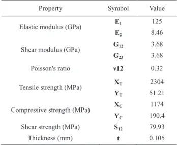
Table 2 Mechanical Properties of USN-125B
3. Testing of Buckling
3.1 Fabrication of Specimen
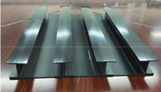
The panel drawing and fabricated stiffened panel are shown in Figs. 3 and 4, respectively. The stiffened panel was composed of skin and four I-type stringers. The stiffened panel was stacked by hand lay-up using USN-125B. The stacking sequences for the skin and stringers were designed to be identical to those of the FEA model. The skin and stringers were fabricated using an autoclave, and the cured skin and stringers were bonded by secondary bonding. The bonding was conducted using BMS 5-129, a film-type adhesive. The curing cycles of the skin and stringer are shown in Figs. 5 and 6, respectively. The top and bottom of the panel were potted using steel blocks to applied a uniform load to the stiffened panel. The blocks were bonded using paste-type adhesive EA9394.
Structure Stacking sequence
Skin [45/0/-45/90/-45/0/-45/90/-45/0/45]
Stringer [45/0/-45/90/90/-45/0/45]s
Property Symbol Value
Elastic modulus (GPa) E1 125
E2 8.46
Shear modulus (GPa) G12 3.68
G23 3.68
Poisson's ratio ν12 0.32
Tensile strength (MPa) XT 2304
YT 51.21
Compressive strength (MPa) XC 1174
YC 190.4
Shear strength (MPa) S12 79.93
Thickness (mm) t 0.105
Fig. 3 Configuration of Stiffened Panel (Unit: mm)
Fig. 4 Stiffened Panel for Compressive Test
Fig. 5 Curing Cycle of UD Prepreg
Fig. 6 Curing Cycle of Adhesive Film
3.2 Test Conditions
A static compressive test was conducted to determine the buckling characteristics of the stiffened panel. The compressive was tested using MTS’s E45 with a 300 kN load cell, at the rate of 0.1 mm/min.
For the compressive test, the stiffened panel was placed on the tester as shown in Fig. 7. Strain gauges were attached to the front and back of the panel center and the load-strain data were obtained from the strain gauges.
Fig. 7 Test Setup of Buckling Test
4. Comparison of Finite Element Analysis and Test Results
4.1 FEA Results
The eigenvalue of the structure can be calculated using the eigenvalue analysis as shown in Eq. (1):
([k]+λ[s]) * {ψ} = 0 (1)
where k is the linear elastic stiffness matrix, s is the geometric stiffness matrix, ψ is the buckling mode geometry, and λ is the eigenvalue. The eigenvalue of the stiffened panel can be calculated using FEA based on Eq. (1). The eigenvalues of each buckling mode are listed in Table 3. The buckling load can be calculated using the eigenvalue obtained from FEA and the load input to FEA, as shown in Eq. 2:
Pcr (N) = λ * P (N) (2)
where Pcr is the buckling load of the structure and P is the load on the structure. The buckling load calculated using Eq.
(2) was 140 kN. Buckling occurred symmetrically at the skin, and the buckling shapes according to the buckling mode are shown in Figs. 8-10.
Fig. 8 Buckling Mode 1 of FEM (Displacement / Fringe)
Fig. 9 Buckling Mode 2 of FEM (Displacement / Fringe)
Fig. 10 Buckling Mode 3 of FEM (Displacement / Fringe)
Table 3 Calculated Eigenvalue of Composite Stiffened Panel
4.2 Buckling Test Results
The load-strain curves of the stiffened panel are shown in Fig. 11. The strains of the front and rear of the stiffened panel showed a linear behavior and then bent in the opposite direction when the buckling occurred. This is a result of the simultaneous occurrence of tensile and compressive deformations due to buckling. The buckling load was obtained by measuring the load of the section where the pre-buckling section of the stiffened panel meets with the post-buckling section in a straight line. The lowest buckling load of 153 kN was measured in the left area. This is because the stringer gaps are different due to the dimension error of the stiffened panel;
consequently, the load bearing capacity of the left area is lower than those of other areas. This buckling load was determined as the buckling load of the stiffened panel.
(a)
(b)
(c)
Fig. 11 Load-Strain Curve of Stiffened Panel ((a) Left Area, (b) Middle Area, (c) Right Area) 4.3 Comparison of Results
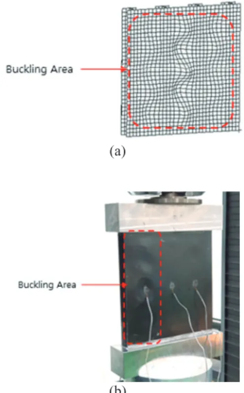
Buckling occurred on the skin as observed in the results of both the FEA and the compressive test. As shown in Figs. 8-10, the buckling mode of the FEA was symmetrical, whereas the buckling mode of the compressive test was asymmetrical;
these results have been compared in Fig. 12. The asymmetry was caused by the difference in load bearing capacity due to dimensional error as explained in the previous section. The buckling loads obtained from the FEA and the mechanical test showed an error of approximately 9.3%, as shown in Table 4.
Buckling Mode Eigenvalue (λ)
1 1.40e+5 2 1.41e+5 3 1.46e+5
(a)
(b)
Fig. 12 Comparison of Buckling Mode ((a) Buckling Mode, (b) Compressive Test)
Table 4 Comparison of Buckling Load
5. Conclusions
In this study, the stringer thickness was designed to be thicker than the skin to induce buckling to predict the buckling characteristics of the stiffened panel. Consequently, the load bearing capacity of the stringer was obtained from the mechanical test and FEA. The stiffened panel was modeled with the selected stacking sequence and then FEA was conducted. The skin and stringers were fabricated using a UD prepreg, and the skins and stringers were bonded using secondary bonding. The ends of the panel were potted using steel blocks to apply the uniform load to the stiffened panels.
Then the testing of buckling was conducted. The FEA result showed that the buckling of the stiffened panel occurred on the skin symmetrically, and the buckling load was 140 kN.
However, for the mechanical test, buckling occurred in the left area first, resulting in an asymmetric shape. The difference in the load bearing capacity due to the manufacturing error of the stringers caused asymmetric buckling, and the buckling load
was determined as 153 kN from the load-strain curve, and the error was insignificant at 9.3% compared with the FEA result.
Acknowledgement
This work was partly supported by the National Research Foundation of Korea (NRF) grant funded by the Ministry of Science and ICT (NRF-2017R1A5A1015311) and the Technology Innovation Program (or Industrial Strategic Technology Development Program) (10074270, Development of Manufacturing Core Technology for 3- Dimensional Woven Integrated Composite Wing Structure of 5,000 Pound VLJ Aircraft) funded By the Ministry of Trade, Industry & Energy (MOTIE, Korea)
References
[1] Y. B. SudhirSastry, P. R. Budarapu, N. Madhavi, and Y.
Krishna, “Buckling analysis of thin wall stiffened composite panels,” Computational Materials Science, vol.
96, pp. 459-471, January 2015.
[2] K. Ghavami and M. R. Khedmati, “Numerical and experimental investigations on the compression behavior of stiffened plates,” Journal of Constructional Steel Research, vol. 62, no. 11, pp. 1087-1100, 2006.
[3] A. Perret, S. Mistou, M. Fazzini, and R. Brault, “Global behavior of a composite stiffened panel in buckling. Part 2:
Experimental investigation,” Composite Structures, vol.
94, no. 2, pp. 376-385, January 2012.
[4] S. P. Heo, W. H. Yang, K. D. Sung, and M. R. Cho, “A Study on the Buckling and Postbuckling Behavior of Laminated Composite Plates and Stiffened Laminated Composite Panels by Finite Element Method,”
Computational Structural Engineering Institute of Korea, vol. 12, no. 4, pp. 599-606, 1999.
[5] L. Boni, D. Fanteria, and A. Lanciotti, “Post-buckling of flat stiffened composite panels: Experiments vs. analysis,”
Composite Structures, vol. 94, no. 12, pp. 3421-3433, December 2012.
[6] H. Abramovich and T. Weller, “Buckling behavior of composite laminated stiffened panels under combined shear-axial compression,” Journal of Aircraft, vol. 45, no.
2, pp. 402-413, March 2008.
[7] S. Zhu, J. Yan, Z. Chen, M. Tong, and Y. Wang, “Effect of the stiffener stiffness on the buckling and post-buckling behavior of stiffened composite panels – Experimental investigation,” Composite Structures, vol. 120, pp. 334- 345, February 2015.
[8] A. Riccio, A. Raimondo, S. Fragale, F. Camerlingo, B.
Gambino, C. Toscano, and D. Tescione, “Delamination buckling and growth phenomena in stiffened composite panels under compression. Part I: An experimental study,”
Buckling Load
FEM Analysis 140 kN
Compressive Test 153 kN
Journal of Composite Materials, vol. 48, no. 23, pp. 2843- 2855, September 2014.
[9] S. Zhang and I. Khan, “Buckling and ultimate capability of plates and stiffened panels in axial compression,”
Marine Structures, vol. 22, no. 4, pp. 791-808, October 2009.
[10] J. Loughlan, “The buckling performance of composite stiffened panel structures subjected to combine in-plane compression and shear loading,” Composite Structures, vol. 29, no. 4, pp. 197-212, January 1994.
[11] R. Zimmermann, H. Klein, and A. King, “Buckling and post buckling of stringer stiffened fibre composite curved panels – Tests and computations,” Composite Structures, vol. 73, no. 4, pp. 150-161, May 2006.
[12] A. Perret, S. Mistou, and M. Fazzini, “Global behavior of a composite stiffened panel in buckling. Part 1: Numerical modelling,” Composite Structures, vol. 93, no. 10, pp.
2610-2618, September 2011.
[13] C. Lynch, A. Murphy, M. Price, and A. Gibson, “The Computational Post Buckling Analysis of Fuselage Stiffened Panels Loaded in Compression,” Thin-Walled Structures, vol. 42, no. 10, pp. 1445-1464, October 2004.