C o p y r ig h t 2 0 0 5 K S A E 1 2 2 5 - 6 3 8 2 / 2 0 0 5 / 0 7 4 - 1 4 T r a ns a c tio ns o f K SA E , V o l. 1 3 , N o . 2 , p p .1 0 1 -1 0 7 (2 0 0 5 )
N o m e nc lature 1 )
A T D C : a fte r to p d e a d c e n te r
B S F C : b ra k e s p e c ific fu e l c o n s u m p tio n , g /k W -h r B T D C : b e fo re to p d e a d c e n te r
E V O : e x h a u s t v a lv e o p e n IV C : in ta k e v a lv e c lo s e
.G A : m ic ro g e n e tic a lg o rith m S O I : s ta rt o f in je c tio n
1 .
*
T o w h o m c o rr e s p o n d e n c e s h o u ld b e a d d re s s e d . m a n s h ik @ e r c .w is c .e d u
S o o t N O x .
.
.
C F D .
.
*
M ike P . L ie c hty R o lf D . R e itz
Engine Research Center, University of Wisconsin-Madison
Optimization of Heavy-Duty Diesel Engine Operating Parameters Using Micro-Genetic Algorithms
Manshik Kim
*Mike P. Liechty Rolf D. Reitz
Engine Research Center, University of Wisconsin-Madison, 1500 Engineering Drive, Madison, Wisconsin 53706, USA (Received 6 September 2004 / Accepted 6 December 2004)
A b s trac t : In th is p a p e r, o p tim iz e d o p e ra tin g p a ra m e te rs w e re fo u n d u s in g m u lti-d im e n s io n a l e n g in e s im u la tio n s o ftw a re (K IV A -3 V ) a n d m ic ro -g e n e tic a lg o rith m fo r h e a v y d u ty d ie s e l e n g in e . T h e e n g in e o p e ra tin g c o n d itio n c o n s id e re d w a s a t 1 ,7 3 7 re v /m in a n d 5 7 % lo a d . E n g in e s im u la tio n m o d e l w a s v a lid a te d u s in g a n e n g in e e q u ip p e d w ith a h ig h p re s s u re e le c tro n ic u n it in je c to r (H E U I) s y s te m . T h re e im p o rta n t p a ra m e te rs w e re u s e d fo r th e o p tim iz a tio n - b o o s t p re s s u re , E G R ra te a n d s ta rt o f in je c tio n tim in g . N u m e ric a l o p tim iz a tio n id e n tifie d H C C I-lik e c o m b u s tio n c h a ra c te ris tic s s h o w in g s ig n ific a n t im p ro v e m e n ts fo r th e s o o t a n d N O x e m is s io n s . T h e o p tim iz e d s o o t a n d N O x e m is s io n s w e re re d u c e d to 0 .0 0 5 g /k W -h r a n d 1 .3 3 g /k W -h r, re s p e c tiv e ly . M o re o v e r, th e o p tim u m re s u lts m e t E P A 2 0 0 7 m a n d a te s a t th e o p e ra tin g p o in t c o n s id e re d .
K e y w o rd s : O p tim iz a tio n ( ), M ic ro g e n e tic a lg o rith m ( ), K IV A -3 V c o d e (K IV A -3 V ),
D ie s e l e n g in e ( )
M ik e P . L ie c h ty R o lf D . R e itz
.
.
1 ),
2 -4 )W ic k m a n
3 )C F D .
K IV A -3 V
5 ). K IV A -3 V
.
2 .
2 .1
, E n g in e R e s e a rc h C e n te r (U W -M a d is o n ) ,
, , K IV A -3 V
.
K H -R T
6 )S h e ll .
7 )S o o t
H iro y a s u
8 )N a g le a n d S tric k la n d -C o n s ta b le
9 )N O x Z e l’d o v ic h
1 0 )
.
. 2 .4 4
. 1 ,7 3 7 re v /m in ,
5 7 % (M o d e 5 ) .
6 0 .1 5 8 m m
. (IV C -E V O )
6 6 0 °
. C
1 4H
3 0M o d e 5 .
.
1 1 )F ig . 1
B T D C 3 0 ° . T a b le 1
.
Fig. 1 Computational grid for the Caterpillar engine at BTDC 30°
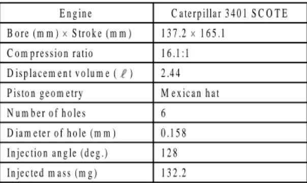
Table 1 Specifications of heavy duty diesel engine and injector
E n g in e C a te rp illa r 3 4 0 1 S C O T E B o re (m m ) × S tro k e (m m ) 1 3 7 .2 × 1 6 5 .1
C o m p re s s io n ra tio 1 6 .1 :1 D is p la c e m e n t v o lu m e ( ) 2 .4 4 P is to n g e o m e try M e x ic a n h a t N u m b e r o f h o le s 6
D ia m e te r o f h o le (m m ) 0 .1 5 8 In je c tio n a n g le (d e g .) 1 2 8 In je c te d m a s s (m g ) 1 3 2 .2
2 .2
S e n e c a l
2 ).G A (M icro
g e n e tic a lg o rith m ) .
.
0 1
. .G A 5
1
(E litis t p re s e rv in g
s e le c tio n ) 4
4 C P U
.
.
(1)
N O x S o o t
. o
E P A 2 0 0 7 .
1 2 )(P M : 0 .0 1 3 4 g /k W -h r, N O x + H C : 1 .7 9 6 g /k W -h r, B S F C : 2 5 6 g /k W -h r)
, .
(T o u rn a m e n t s e le c tio n )
(C ro s s o v e r) .
. , E G R
T a b le 2 .
Table 2 Variation of engine operating parameters B o o s t p re s s u re (k P a ) 1 3 0 ~ 2 2 0 , 4 s te p s E G R ra te (% ) 0 .0 ~ 5 0 .0 , 3 2 s te p s S O I tim in g (A T D C d e g .) -6 0 .0 ~ 2 0 .0 , 3 2 s te p s
3 .
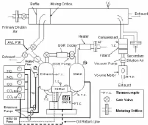
F ig . 2 K IV A -3 V . E G R 5 0 %
Fig. 2 Engine laboratory setup with dilution tunnel and EGR system
.
S o o t, H C , N O x
. E G R 0 %
-3 .5 ° A T D C 5 .5 ° A T D C 2 ° C A
-5 .5 ° A T D C E G R 0 %
~ 2 3 .5 % .
4 .
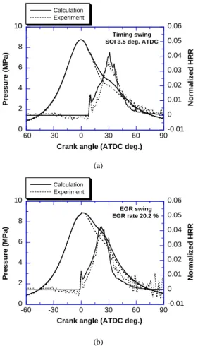
4 .1 F ig . 3
. F ig . 3 (a ) 3 (b ) E G R
.
.
. F ig . 4
.
S o o t N O x
.
M an s h ik K im M ik e P . L ie c h ty R o lf D . R e itz
0 2 4 6 8 10
-0.01 0 0.01 0.02 0.03 0.04 0.05 0.06
-60 -30 0 30 60 90
Timing swing SOI 3.5 deg. ATDC Calculation
Experiment
Pressure (MPa) Normalized HRR
Crank angle (ATDC deg.) (a)
0 2 4 6 8 10
-0.01 0 0.01 0.02 0.03 0.04 0.05 0.06
-60 -30 0 30 60 90
EGR swing EGR rate 20.2 % Calculation
Experiment
Pressure (MPa) Normalized HRR
Crank angle (ATDC deg.)
(b)
Fig. 3 Cylinder pressure and heat release rate comparison between the experiment and calculation
0 0.5 1 1.5 2 2.5
0 5 10 15 20 25 30
Timing swing (expt.) Timing swing (cal.) EGR swing (expt.) EGR swing (cal.)
Soot (g/kg-f)
NOx (g/kg-f)
Fig. 4 Comparison of emission characteristics
4 .2 F ig . 5
0 100 200 300 400 500 600
0 50 100 150 200
Maximum merit value
Generation number Fig. 5 Mode 5 three-factor GA merit vs. generation
-5 0 5 10 15 20
-600 0 600 1200 1800 2400
-60 -40 -20 0 20 40 60
Pressure (MPa) Rate of heat release (J/deg.)
Crank angle (ATDC deg.)
Fig. 6 Cylinder pressure and heat release rate of the optimum case
. 5
7 4
. 7 4
.
2 2 0 k P a , E G R 4 6 .6
% , -6 0 ° A T D C . F ig . 6
.
. S o o t
E G R N O x
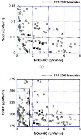
(S o o t : 0 .0 0 5 g /k W -h r, N O x + H C : 1 .3 3 g /k W -h r). F ig .
7 (a ) N O x + H C - S o o t, (b )
N O x + H C - B S F C
O p tim iz atio n o f H e av y - D u ty D ie s e l E n g in e O p e ratin g P aram e te rs U s in g M ic ro - G e n e tic A lg o rith m s
. E P A
2 0 0 7
.
N O x E G R
N O x S o o t H C C I
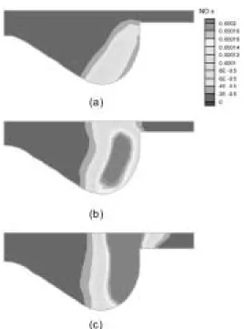
-6 0 ° A T D C . F ig . 8
. -6 0 ° A T D C -2 7 ° A T D C
. 1 5 0 M P a
.
0 0.05 0.1 0.15
0 2 4 6 8
Soot (g/kW-hr)
NOx+HC (g/kW-hr)
EPA 2007 Mandates
(a)
175 200 225 250 275
0 2 4 6 8
BSFC (g/kW-hr)
NOx+HC (g/kW-hr)
EPA 2007 Mandates