• 검색 결과가 없습니다.

Analysis of leakage factors affecting ECV performance in variable compressor

N/A
N/A
Protected

Academic year: 2021

Share "Analysis of leakage factors affecting ECV performance in variable compressor"

Copied!
6
0
0

로드 중.... (전체 텍스트 보기)

전체 글

(1)

Abstract

Solenoid operated electromagnetic control valve (ECV) using in an external variable displacement swash plate type compressor is widely used for air conditioning control system because of its low energy consumption and high efficient characteristics. ECV controls the entire vehicle air conditioning system by means of a pulse width modulation (PWM) system that supplied from an external controller. Different pressure ports located within ECV has important functions to control the air/refrigerant flow through its internal passages. The flow paths are preciously maintained with acceptable ranges of leakage (gap) between the parts inside it which is followed by effective design and critical dimensioning of its internal features. Therefore, it saves energy losses from the solenoid operation as well as ensures the balance of forces within it. The research paper highlights analysis of the leakages (at different pressure ports) and dimensioning tolerance factors that affects the ECV performance.

Key words : Electromagnetic control valve (ECV); Pulse width modulation (PWM); Variable compressor;

Leakage; Air conditioning

1. Introduction

At present, automotive industries are more careful about producing high efficiency vehicles. Increase in fuel price and adaptation of new technologies refers to demand of high efficiency vehicles [1].

Air conditioning application is one of the major issues in every vehicle for its passenger comfort and thus it is playing an important role towards high efficiency vehicles. The vehicle air conditioning system has a compressor coupled to a solenoid operated electromagnetic control valve (ECV) [2]. Compressors using for vehicle air conditioning system, consumes a lot of engine power as it is a high efficiency requiring component. ECV that uses in external variable

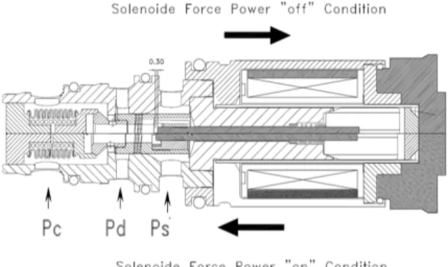
capacity type compressor is a kind of electromechanical device used to control the flow of air/refrigerant by passing an electric current through a coiled wire, thereby altering the valve position [3]. In the automotive field, the solenoid valves are used as actuators and to control fluid pressure. The types of solenoid valves that are used are 'idle speed control valves, shift control valves of automatic transmissions and torque converter locked-up control valves' [4]. In the variable compressor, it senses suction pressure and controls the swash plate angle based on crankcase-suction pressure differential. Operation of control valve is dependent on a difference in pressure [5].

Moreover, the capacity of the compressor is changed by changing the inclination of the angle of the swash plate which is controlled by the suction pressure in the crank chamber [6]. The inclination angle of swash plate refers to the suction pressure that results the flow rate of air/refrigerant in the

To whom corresponding should be addressed.

Division of Mechanical and Automotive Engineering, Kongju National University (KNU) 275, Budae-dong, Cheonan-si, Chungcheongnam-do 331-717, South Korea

Tel. 041-521-9287 E-mail : [email protected]

(2)

refrigerant circuit corresponding to the cooling load [7]. ECV is an electromagnetically actuated control valve that controls a plunger stroke according to the amount of current supplied from the external controller in the solenoid coil. The solenoid valve is driven by PWM input signal from an external source that is free of ripple pressure [8].

Fig. 1 shows variable displacement swash plate type compressor with external control valve i.e.

ECV and fig. 2 shows the operating principle of the ECV in the compressor. Basically ECV controls the operation of a compressor by using the transmitted electric signal from the vehicle's ECU. In the fig. 2, the directions of the solenoid forces indicate switched on (engage the current with PWM to ECV) and switched off (disengage the current with PWM to ECV) condition. In 'switched on' condition, the force generates in the solenoid as to move the armature in the direction of bellows whereas, in 'switched off' condition, the force of bellows is used to return to the original position.

For calculating the solenoid (working) force (F), following equation is used in this case [9],

Where, 0 = Permeability of a vacuum (gap between core and plunger) and it has a finite value of about 1.257×10⁻⁶ Hm-1; N = Number of coil turns in the solenoid; i = Supply of current; =

Solenoid efficiency without energy losses; Ac.s. = Cross sectional area of the part through which the total magnetic flux flows and Pst = Plunger stroke (the effective gap length between the core and plunger).

Secondly, balance of forces is also an important consideration for ECV performance and the following equation represents the balance of forces inside an ECV.

Where, Fm = solenoid magnetic force, Fh = hydraulic force, Ps = suction chamber pressure, As

= area applied by suction pressure, Fplunger spring

= plunger spring force, Fbellows spring = bellows assay spring force, Fc = crankcase chamber force, Pc = crankcase chamber pressure, Ac = area applied by crankcase pressure and Faerodynamic = aerodynamic force. Solenoid magnetic force is considered as a principle force prior to all other forces. Therefore, it is proportional to the total working force, and can be written as,

Again, as it is importantly needed to control the air pressure in different pressure ports; internal components would need to be very precise and accurate in design. In some cases, tolerance for Fig. 1. Variable displacement swash plate type compressor Fig. 2. ECV in switch on and off condition and working

of solenoid force

(3)

each component of ECV is ±0.02mm to ±0.05mm, whereas some of the components associated with the leakage performance are assembled within a tolerance of ±0.002mm which is definitely a challenging issue to obtain.

Fig. 3 and 4 shows the pressure incoming and outgoing cases depend on the port operation due to the movement of internal features caused by the with and without supply of current respectively. Movement of internal components affects the performance of entire ECV. The operation of ECV uses a principle in which the pressure supplied to Pc to Ps and Pd to Pc according to the operating conditions.

2. Factors affecting ECV performance

ECV contains different internal components such as valve body, guide valve, guide pin, core, plunger, plunger pin, plunger spring, bellows etc.

All these components are assembled into a single product to make it to form ECV. In ECV; different port locations, flow path geometry, leakage rate,

tolerance limits etc. needs to fix to a standard level to obtain highest mechanical performance. The leakage flow rate is observed by the difference (clearance) between the diameters of the two internal components as shown in Fig. 5. Here for an example, assembly clearance between the valve body and guide valve fixes to 0.075mm. Here the difference in the diameter is necessary because, as the guide is moved by the guide pin after supplying the current, a little bit of space is required in order to movement of guide.

On the other hand, guide valve length is also is considerable factor as it is related to the Pc port pressure. When the current is supplied, internal components starts to move forward with certain solenoid force and the length of the guide define the Pc port pressure rate. Increase of guide length increases the Pc flow. This guide length is fixed by punching the guide pin inside guide valve with different pressure set up with the help of ECV assembling machine that duly assembled/fixed with the plunger hole. Fig. 6 shows the Pc flow rate Fig. 3. Flow from P

c

to P

s

port location (switched on) Fig. 4. Flow from P

d

to P

c

port location (switched off)

Fig. 5. Clearance (for flow) between Guide and Valve body )

Fig. 6. Change in P

c

flow with the change of guide

valve length

(4)

with respect to changing the guide lengths (15.10mm, 15.13mm, 15.16mm and 15.19mm) for a three different ECV samples. It is seen that with the increase of guide length, Pc flow increases. It is importantly need to mention here that, when the guide valve, guide pin, core and plunger assembled together; the unit called core assay. And the guide length is increased or decreased by punching when is in under core assay but not when it is an individual item.

3. Experimental procedures

For experimental analysis, an air board tester is used which is being developed for the leakage test and flow test at different pressure port locations.

Fig. 7 shows the air board tester for experiment i.e.

measures the initial flow rate and leakage rate of ECV. For leakage test; different parameters on the board setting as (a) maximum high pressure: 0.69 bar, (b) DC power supply: 23.2V, (c) duty controller power supply: 13.5V, (d) current supply range: 0.20Amp~0.95Amp, (e) frequency:

400±10Hz, (f) duty: 0~100%.

Fig. 8 shows the effect of Ps leakage due to changing in punching pressure at different pressure set up for three ECV samples. When punching is carried out, each component of ECV undergoes a plastic deformation, which in return impacts the performance between components. In is seen that, leakage at Ps port gradually decreases with the increase of punching pressure during assembly operation.

Again, fig. 9 shows Ps leakage with respect to difference in diameter. Here difference in diameter indicates the clearance between the valve body and guide i.e. in other words inner diameter of the valve body and outer diameter of the guide. It is seen that, the clearance is of small values. As mention earlier some of the components associated with the leakage performance are assembled within a tolerance of ±0.002mm; here is the challenge to maintain the tolerance limit values. The more is the clearance; more is the leakage at the Ps pressure port location.

Fig. 7. Air board tester Fig. 8. Leakage at P

s

port of ECV with respect to changing in punching pressure

Fig. 9. P

s

leakage with respect to difference in diameter

(5)

the length of the guide. The bellows cap, which is supported at the end of the guide by the end face of the guide, is a component that forms a flow path from Pd to Pc. Plunger spring that supports the force of the ECV, by its nature, the bellows contacts the end of the guide, thereby determining the compression of the bellows through the length of the guide. Here, the length of the guide increased from 15.10mm to 15.19mm and initial flow rate at Pc increased from 61 to 73 which are quite linear in nature. This is an important factor that the leakage rate is almost linear which ensures the movement of plunger (connected to the guide through a guide pin) due to supply of current is in proper condition.

Secondly, in case of leakage at Ps, punching pressure affects the leakage (fig. 8). Leakage performance at the closed unit of ECV, the plastic strain varies in accordance with the punching surface material which is needed to be considered carefully. When the core assay punched at high punching pressure; leakage at the port is tends to become small/zero but in case of low punching pressure leakage increased. That means during punching the pressure is need to consider very careful for getting viable leakage output followed by proper matching within components.

Thirdly, again leakage at Ps affects by the clearance between the valve body and guide valve (fig. 9). In this case it is very important to maintain the clearance at precise tolerances. It should not meet the zero tolerance but very critical tolerance value. It is seen from the figure that with the increase in clearance 0.002mm gradually from

within the compressor is closely related to the vehicle's fuel consumption as well as its efficiency.

In this regard, the design of different components of ECV should meet the standard technical requirements as well as economic production costs as these factors are directly affects the entire performance of an ECV.

ACKNOWLEDGMENT

This research work is financially supported by the Ministry of Education, Science Technology (MEST) and National Research Foundation (NRF) of Republic of Korea through the Human Resource Training Project for Regional Innovation (No.

201212A0106113010100).

References

1. Y. J. Lee, G. H. Lee and B. E. Lim, "Noise Evaluation of a Control Valve in a Variable Compressor", 4th International Conference on Sustainable Automotive Technologies, RMIT University, Melbourne, Australia, (2012), p337-341.

2. Y. Huang, R. J. Callahan, S. A. Harte, and L.

W. Smith, "Electronic control strategy for A/C compressor", United States Patent no.

6675592B2. (2004).

3. S. V. Angadi, R. L. Jackson, S. Y. Choe, G.

T. Flowers, J. C. Suhling, Y. K. Chang and J.

K. Ham, "Reliability and life study of

hydraulic solenoid valve. Part 1: A multi-

physics finite element model", Engineering

(6)

stuck fault detection", International Journal of Heavy Vehicle System, Vol. 14, No. 1 (2007), p20-35.

5. B. H. Dwiggins, "Automotive Air Conditioning", 8th edition, Thomson Learning Inc. New York, USA (2002).

6. Y. Takano, H. Kishita, K. Yamasaki and Y.

Niimi, "Compressor control device for vehicle air conditioner", United States Patent no.

5867996A (1999).

7. U. Satoshi, H. Tatsuya, M. Kazuhiko, H. Yuji, N. Masami and O. Masaki, "Control valve of variable displacement compressor", United States Patent no. 6637228 (2003).

8. G. S. Lee, H. J. Sung and H. C. Kim,

"Multiphysics analysis of a linear control solenoid valve", Journal of Fluids Engineering, Transactions of the ASME, 135/011104 (2013), p1-10.

9. Md. Iqbal Mahmud and Haeng Muk Cho,

"Analysis of forces in an automobile ECV

using in external variable displacement swash

plate type compressor for air conditioning

control system", Journal of Mechanical

Science and Technology, Vol. 28, No. 5

(2014), p1979~1984.

수치

Fig.  1  shows  variable  displacement  swash  plate  type  compressor  with  external  control  valve  i.e
Fig.  5.  Clearance  (for  flow)  between  Guide  and  Valve  body  )
Fig.  7.  Air  board  tester Fig.  8.  Leakage  at  P s     port  of  ECV  with  respect  to  changing  in  punching  pressure

참조

관련 문서

In this study, the existing material of the air conditioner compressor and Al6061 material were applied through structural analysis and fluid-structure coupling analysis using

S., An Experimental Study on the Cooling and Heating Performance of a Residential Ground Source Heat Pump System, Korean Journal of Air-Conditioning

Performance shaping factors (PSFs) are factors that influence human performance in human reliability analysis (HRA) [1,2]. Typical examples of PSFs

• An arrow with a negative sign (-): all else remaining equal, an increase (decrease) in the first variable decreases (increases) the second variable below (above) what

: At a critical point an infinitesimal variation of the independent variable results in no change in the value of the function..

 An ODE contains one dependent variable, one independent variable, and ordinary derivatives of the dependent variable.  Any linear ODE can be written in the

Because the functions of the step-up, step-down control operation and variable switching frequency using the linear congruential generator (LCG) are

The change of Chinese government's policy, which has already changed the business environment to invest in China or the plans to enter China, is an important variable