CopyrightⒸ2014 KSAE / 131-08 pISSN 1225-6382 / eISSN 2234-0149 DOI http://dx.doi.org/10.7467/KSAE.2014.22.5.050
< 기 술 논 문 >
Transactions of KSAE, Vol. 22, No. 5, pp.50-58 (2014)
한국형 소형궤도차량(PRT)의 내구성 및 주행안정성 평가 연구
조 정 길1)․김 준 우1)․김 현 태1)․구 정 서*1)․강 석 원2)․정 락 교2)
서울과학기술대학교 철도차량시스템공학과1)․한국철도기술연구원 수요응답형교통연구단TFT2)
A Study on the Durability and Running Stability Evaluation of the Korean PRT
Jeonggil Cho1)․Junwoo Kim1)․Hyuntae Kim1)․Jeongseo Koo*1)․Seokwon Kang2)․Raggyo Jeong2)
1)
Department of Rolling Stock System, Seoul National University of Science and Technology, Seoul 139-743, Korea
2)
On-Demand Transit Research Team, Korea Railroad Research Institute, 176 Cheoldobangmulgwan-ro, Uiwang-si, Gyeonggi 437-757, Korea
(Received 1 November 2013 / Revised 10 December 2013 / Accepted 17 December 2013)
Abstract : The PRT(Personal Rapid Transit) system is highly interested to meet a need for demand-responsive transport service and increasing demands of traffic in Korea recently. And it is being spotlighted as an eco-friendly transportation system. For these reasons, researches on the PRT system are actively undergoing in Korea. In this study, we evaluated the static structural and fatigue strengths based on ASCE-APM standards and ERRI B 12/RP 17 by means of FE simulation. We also evaluate the running stability by multi-body dynamic analyses and the rollover safety by a theoretical static stability factor according to the road modeling scenarios for the PRT system. From the results of this study, we confirmed the durability and running stability of the Korean PRT under development.
Key words : Personal rapid transit(소형궤도차량), Static strength(정적강도), Fatigue strength(피로강도), Running stability(주행안정성), Static stability factor(정적 안정 계수)
Nomenclature
1)g : gravitational acceleration, m/s
2a
y: lateral acceleration, m/s
2m : mass, kg
v : velocity, m/s
: alternating stress, kg
f/mm
2
: fatigue strength, kg
f/mm
2
: mean stress, kg
f/mm
2
: ultimate strength, kg
f/mm
2n : fatigue safety index t : wheel track, mm
h : height of gravitational center, mm
*Corresponding author, E-mail: [email protected]
F : reaction force, kg
f : road gradient, rad r : radius of curve, m
Subscripts Max : maximum
Min : minimum L : left side R : right side
1. 서 론
전 세계적으로 고효율, 친환경 녹색 교통시스템
에 대한 수요와 소규모 맞춤형 교통수단의 요구, 대
한국형 소형궤도차량(PRT)의 내구성 및 주행안정성 평가 연구
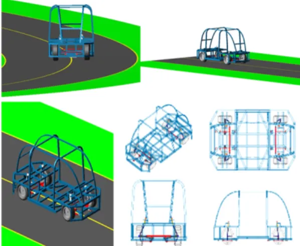
Fig. 1 Concept drawing of the Korean PRT
중교통의 단점을 보완하고자 기존의 Mass-transit 개 념에서 벗어난 Para-transit 개념에 가까운 PRT(Per- sonal Rapid Transit)시스템의 연구/개발이 활발히 이 루어지고 있다.
1-4)PRT 시스템은 설치비용이 지하철의 1/10, 경전철 의 1/3 정도로 경제적이며, 무인 자동운전 및 탑승객 의 원하는 목적지까지 네트워크상의 다양한 경로 중 최적의 경로를 자동으로 선택하여 논스톱으로 주행이 가능하여 국내의 늘어나는 교통수요를 대체 할 수 있는 신 교통시스템이다.
이러한 장점을 기반으로 현재 유럽과 미국을 중 심으로 활발히 연구가 진행되고 있으며 영국의 히 드로공항
5)과 UAE의 마스다르시에서 상용노선을 건설하여 운영되고 있다. 하지만 국내에서는 아직 본격적인 운행구간이 없으며 순천만 인근에서 시범 운영 중이다.
6)현재 한국철도기술연구원에서는 해외에서 운영 되고 있는 PRT 시스템과 차별화 된 온라인 무선급 전, 4륜 조향, 자기센서기반의 무인 자율주행의 기 능을 갖춘 한국형 PRT 시스템 개발과정 중이다. 본 연구에서는 한국철도기술연구원 개발 중인 한국형 PRT차량의 모델을 지원 받아서 구조/피로강도 및 주행/전복안정성 평가를 진행하였다.
PRT 차량의 경우 국내외적으로 내구성 평가를 위한 독립적인 기준이 없는 실정이다. 따라서 American Society of Civil Engineers - Automated People Mover Standards
7)에 근거하여 연구하였다.
2. PRT 차체프레임의 내구성 평가
2.1 평가기준ASCE - APM Standards에 근거하여 Table 1과 같이
Table 1 Performance test standard for ASCE-APM Loading
conditions Load calculation method Calcurated load AW0
(Weight of an empty vehicle)
Weight of an empty vehicle 0.9 [ton]
AW1 (Design load)
AW0
+712[N] per passenger, multiplied by the design capacity
1.19 [ton]
AW2 (Maximum operating load)
AW0
+712[N] per Max. number of passenger
1.34 [ton]
AW3 (Crush load)
AW0
+5120[N/m2] per standee floor area +712[N] per seat
+5120[N/m2] If luggage racks are provided
Table 2 Maximum operating load conditions by the ASCE-APM
Case Loads
①Lateral load AW2*0.24g 0.32[ton]
②Vertical load AW2*1.2g 1.61[ton]
③Longitudinal load AW2*0.34g 0.46[ton]
④Vertical &
Compressive load
Vertical load AW2*1.2g 1.61[ton]
Compressive
load AW0 0.9[ton]
Table 3 Normal operating load conditions by the ASCE-APM
Case Loads
①Lateral load AW1*0.24g 0.29[ton]
②Vertical load AW1*1.2g 1.43[ton]
③Longitudinal load AW1*0.25g 0.30[ton]
설계하중을 정립하였으며 이를 이용하여 Table 2, 3 과 같은 최대운영하중조건 및 일반운영하중조건을 산출하였다.
2.2 차체프레임의 유한요소모델
구조/피로강도 평가를 위해 Fig. 2와 같이 shell요
소를 적용한 유한요소모델을 구성하였다. 재료의
기계적 성질은 Table 4와 같고, 유한요소모델의 제
원은 Table 5와 같다. 본 연구에서 사용한 선형해석
프로그램은 Altair사의 Hyperworks Radioss
8)를 이용
하였다.
Jeonggil Cho․Junwoo Kim․Hyuntae Kim․Jeongseo Koo․Seokwon Kang․Raggyo Jeong
Fig. 2 FE model of the Korean PRT bare frame Table 4 Mechanical properties of material
A6N01-T5
Tensile strength [kgf/mm2]
Yield stress [kgf/mm2]
Fatigue stress [kgf/mm2] Base zone Base
zone Weld
zone Base zone
Weld zone
27.5 22.9 11.7 7.14 3
Elastic modulus
[kgf/mm2] Poisson's ratio Density [kg/mm3] 7.0 × 10³ 0.33 2.7 × 10⁻⁶
Table 5 FE model data of the Korean PRT
Bare frame of the PRT
Number of nodes [EA] 111937
Number of elements [EA] 116705
Mean element size[mm] 12
2.3 최대운영하중조건을 이용한 구조강도 평가
Table 2의 4개의 하중과 이들을 조합한 3개의복합 하중에 대한 구조강도평가를 실시하였다.
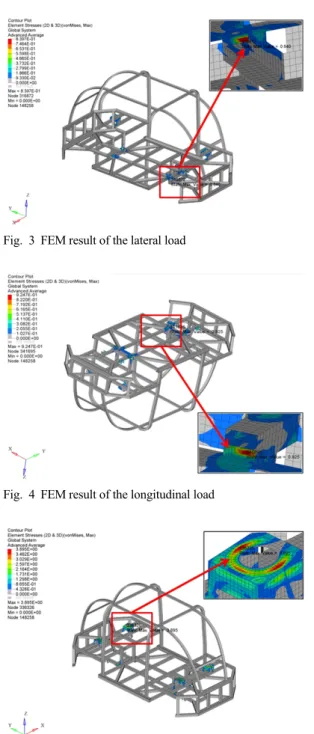
해석결과, Fig. 3의 횡방향 하중(lateral load)과 Fig.
4의 종방향 하중(longitudinal load)에서의 최대등가 응력은 하부프레임의 용접부에서 발생하였으며 Fig. 5의 수직방향 하중(vertical load)과 Fig. 6의 수직 방향 및 압축하중(vertical & compressive load)에서 의 최대등가응력은 현가장치 마운트 취부에서 발생 하였다.
Table 6에서와 같이 복합하중 해석결과를 포함하 여 모두 용접부에서 최대등가응력을 확인할 수 있 었으며 용접부 항복강도를 충분히 만족함을 확인하 였다.
Fig. 3 FEM result of the lateral load
Fig. 4 FEM result of the longitudinal load
Fig. 5 FEM result of the vertical load
2.4 일반운영하중조건을 이용한 피로강도 평가
본 연구에서는 국내도시철도의 일반적인 피로
강도평가 방법 대신 ERRI B 12/RP 17
9)에 근거한
피로강도 평가를 실시하였다. 계산절차는 다음과
같다.
A Study on the Durability and Running Stability Evaluation of the Korean PRT
Fig. 6 FEM result of the vertical & compressive load
Table 6 FEM results according to maximum operating load conditions of the ASCE-APM
Loading conditions Max. von Mises stress (kgf/mm2)
Yield stress (kgf/mm2)
①Lateral load 0.840 (weld zone)
11.7 (weld zone)
②Longitudinal load 0.925 (weld zone)
③Verticalload 3.895 (weld zone)
④Vertical load &
Compressive load 4.105 (weld zone)
⑤Vertical load &
Lateral load 4.368 (weld zone)
⑥Vertical load &
Longitudinal load 4.074 (weld zone)
⑦ Lateral load &
Longitudinal load 1.737 (weld zone)
① ASCE-APM의 일반운영하중조건 3종류에 대한 해석결과 각각의 주응력과 주응력의 방향을 구 한다.
② 최대 주응력을 갖는 하중조건을 구하고 주응력 의 방향을 결정한다.
③ 이전단계에서 구해진 주응력방향으로 나머지 하 중조건에서 얻어진 응력을 변환하고 최소주응력 을 계산한다.
④ 이렇게 구해진 최대주응력과 최소주응력을 이용 하여 평균응력과 응력진폭을 식 (1)을 이용하여 계산한다.
주요 절점에서의 평균응력과 응력진폭을 계산 후 식 (2)를 이용하여 피로안전계수를 계산할 수 있다.
max
min,
max
min(1)
Fig. 7 Goodman diagram for the Korean PRT
Table 7 FEM results according to normal operating load conditions of the ASCE-APM
Element number
Max.
principal stress
Min.
principal stress
Fatigue safety index
412264 4.47 0.1 2.23 2.23 0.83
207544 4.45 -0.14 2.23 2.22 0.82
412265 3.70 0.21 1.85 1.85 0.68
411380 4.47 0.18 2.23 2.23 0.83
412069 3.54 -0.05 1.78 1.76 0.65
Fig. 8 High stress locations under the normal operating load conditions
(2)
식 (2)에 의한 피로안전계수가 1보다 낮으면 무한
수명을 만족하는 것으로 평가 할 수 있으며 피로안전
계수가 높은 주요부분에 대해 Table 7에 정리하였다.
10)조정길․김준우․김현태․구정서․강석원․정락교
Fig. 7은 일반운영하중조건에 대한 PRT 차체 프 레임의 주요부분에 대한 Goodman선도를 나타낸 것 이다. 여기서 알 수 있듯이 주요부분은 용접부이며 피로안전도를 만족함을 알 수 있다.
3. PRT 차량의 주행안정성 평가
3.1 평가기준PRT 차량의 차량의 주행안정성 평가를 위해 ASCE - APM Standards에 근거하여 Table 8의 평가기준을 적용하였다. 본 연구에서 고려중인 PRT차량은 입석 (standing area)이 없이 모든 승객이 앉아있는 상태를 고려하였다.
Table 8 Maximum sustained acceleration conditions by the ASCE-APM
Direction Standing Seated
Lateral ±0.10 g ±0.25 g
Vertical ±0.25 g ±0.25 g
Longitudinal normal ±0.16 g ±0.35 g Longitudinal emergency ±0.32 g ±0.60 g
3.2 PRT차량의 동역학 모델
본 연구에서는 차량의 동적 거동을 위한 시뮬레 이션으로서 신뢰성이 검증된 자동차 전용 동역학 해석프로그램인 ADAMS/CAR
11)를 사용하였으며 차량의 제원은 Table 9와 같고 Fig. 9와 같이 모델을 구성하였다.
Fig. 9 Adams/car model of the Korean PRT
Table 9 Specification of the Korean PRT
Item Data
Wheel base 2300mm
Wheel track 1200mm
Suspension (Front/Rear) Macpherson strut type Steering system Four wheel steering
Tire size 155/70R13
Vehicle weight (Empty) 900kg Vehicle weight (Full) 1,300kg
3.3 전용노선의 시나리오
일반적인 도로의 평면선형은 승용차, 대형트럭, 버스 등이 혼합되어 있기 때문에 도로의 설계속도 에 따라 다양한 형태의 자동차 주행에 무리가 없도 록 직선, 원곡선, 완화곡선을 균형적인 길이 및 크기 로 일관성 있는 흐름을 갖도록 설계되고 있다. 하지 만 본 연구에서 고려하는 PRT 차량의 노선은 다른 형태의 차량과 같이 주행하지 않는 전용노선시스템 이다. 따라서 PRT 차량만의 특성을 고려한 전용노 선 설계가 필요하다.
PRT 차량이 목표로 하는 설계최고속도 및 운행 최고속도는 각각 50km/h, 40km/h이다. 도로규정의 완화곡선 및 완화구간 설치는 설계속도 60km/h 이 상의 도로에서는 완화곡선으로, 설계속도 60km/h 미만에서는 완화구간으로 하도록 하고 있으나, 지 형여건 상 부득이한 경우를 제외하곤 완화구간을 완화곡선으로 설치하도록 권고하고 있다.
하지만 PRT 차량 전용노선의 경우 일반적인 도 로규정을 막연히 적용하기 보다는 차량 주행특성을 반영하여 전용노선의 곡선반경을 최소화 한다면 건 설비를 저감할 수 있다. 따라서 설계속도에 따른 완 화구간의 길이는 설계최고속도 50km/h에 해당하는 30m를 반영하였으며 그 이하의 20m, 10m, 그리고 완화곡선이 아닌 완화구간 30m의 조건들에 대한 해 석을 진행하여 최적의 전용노선 조건을 찾고자 하 였다.
이를 고려한 전용노선 시나리오를 Table 10과 같
이 정리하였다. 운행조건은 가감속도 없는 50km/h
의 일정속도로 직선부-완화곡선 및 완화구간-원곡
선-완화곡선 및 완화구간-직선부로 구성하였으며
공차상태 및 만차상태에 따른 곡선반경 80 ~ 90m의
한국형 소형궤도차량(PRT)의 내구성 및 주행안정성 평가 연구
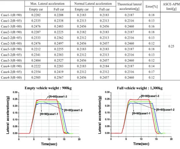
Table 11 Lateral accelerations of the all case
Max. Lateral acceleration Normal Lateral acceleration Theoretical lateral
acceleration[g] Error[%] ASCE-APM limit[g]
Empty car Full car Empty car Full car
Case1-1(R=90) 0.2202 0.2208 0.2183 0.2183 0.2187 0.18
0.25
Case1-2(R=85) 0.2335 0.2338 0.2313 0.2313 0.2316 0.13
Case1-3(R=80) 0.2476 0.2483 0.2456 0.2456 0.2460 0.16
Case2-1(R=90) 0.2207 0.2225 0.2182 0.2183 0.2187 0.18
Case2-2(R=85) 0.2333 0.2362 0.2312 0.2313 0.2316 0.13
Case2-3(R=80) 0.2476 0.2497 0.2456 0.2457 0.2460 0.12
Case3-1(R=90) 0.2212 0.2255 0.2183 0.2183 0.2187 0.18
Case3-2(R=85) 0.2341 0.2383 0.2312 0.2313 0.2316 0.13
Case3-3(R=80) 0.2484 0.2527 0.2456 0.2457 0.2460 0.12
Case4-1(R=90) 0.2222 0.2283 0.2183 0.2184 0.2187 0.14
Case4-2(R=85) 0.2354 0.2419 0.2312 0.2312 0.2316 0.17
Case4-3(R=80) 0.2505 0.2567 0.2456 0.2457 0.2460 0.12
Fig. 10 Lateral accelerations of Case 1 (empty vehicle) Fig. 11 Lateral accelerations of Case 1 (full vehicle) Table 10 PRT road modeling scenarios
Straight section
Transition curve/part section
Circular curve
Case1-1
50m
Transition curve 30m
R=90m
Case1-2 R=85m
Case1-3 R=80m
Case2-1
Transition curve 20m
R=90m
Case2-2 R=85m
Case2-3 R=80m
Case3-1
Transition curve 10m
R=90m
Case3-2 R=85m
Case3-3 R=80m
Case4-1
Transition part 30m
R=90m
Case4-2 R=85m
Case4-3 R=80m
편경사 6% 조건으로 진행하였다. 그리고 타이어와 노면사이의 마찰계수는 일반적인 아스팔트의 건조 한 상태에서의 마찰계수 1을 적용하였다.
3.4 시나리오조건을 반영한 주행안정성 평가
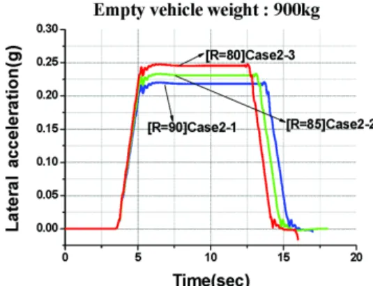
해석결과를 Fig. 10 ~ 17과 Table 11에 정리하였으 며 모든 시나리오 조건에서 곡선의 추종성과 횡가 속도 한계를 만족하였다. 그리고 Case 1 ~ 3의 경우 완화곡선을 적용하였기 때문에 완화구간을 적용한 Case 4에 비해 최대 횡가속도가 상대적으로 낮은 경 향을 보이지만 그 차이는 매우 작은 편이며 원곡선 에 진입한 상태에서는 거의 동일하였다.
공차조건과 만차조건을 비교하면 완화곡선 및 완
화구간 끝부분에서의 횡가속도가 원곡선의 중간부
Jeonggil Cho․Junwoo Kim․Hyuntae Kim․Jeongseo Koo․Seokwon Kang․Raggyo Jeong
Fig. 12 Lateral accelerations of Case 2 (empty vehicle) Fig. 13 Lateral accelerations of Case 2 (full vehicle)
Fig. 14 Lateral accelerations of Case 3 (empty vehicle) Fig. 15 Lateral accelerations of Case 3 (full vehicle)
Fig. 16 Lateral accelerations of Case 4 (empty vehicle) Fig. 17 Lateral accelerations of Case 4 (full vehicle)
분에 비해 약간 상승하는 경향이 있으며 완만한 상 승곡선이 아닌데 이는 가속도의 변화율 즉, 저크의 영향으로 인한 결과로 판단된다.
원곡선의 반경에 따른 해석결과와 이론식에 의한 횡가속도는 오차범위 이내에서 잘 일치하였으며, Case 4의 R=80m에서 기준치인 0.25g를 순간적으로
초과하나 대부분 기준치 이내를 만족하였다.
4. PRT 차량의 전복위험도 평가
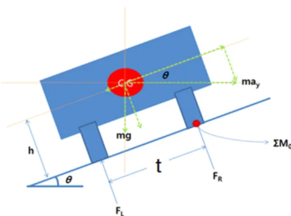
4.1 Static Stability FactorPRT 차량의 곡선부 주행시 전복위험도를 평가하
기 위해서 Fig. 18과 같이 강체의 차량이 정상상태에
A Study on the Durability and Running Stability Evaluation of the Korean PRT
Fig. 18 Simple PRT rollover model
서 오른쪽 휠을 기준으로 전복한다고 가정하여 모 멘트평형방정식을 세우면 식 (3)과 같다.
∑
(3)
여기서 도로의 경사는 매우 작다고 가정(sinθ=0) 하고 전복이 시작될 때 왼쪽 휠의 반력이 영이 되는 조건(F
L=0)을 고려하여 정리하면 식 (4)와 같다.
(4)
식 (4)와 같이 차량의 윤거와 무게중심의 위치를 이용한 조건을 Static stability factor(SSF)라고 하며 전복위험도를 판정하는 중요한 지수로 활용되고 있 다.
12)SSF가 높을수록 전복위험도가 낮으며 일반적 인 승용차의 경우 1.3 ~ 1.5이며 차체가 높은 SUV의 경우 1.1 ~ 1.3정도를 나타낸다.
한국형 PRT 차량의 경우 아직 연구개발 중이지만 윤거가 1200(mm)이며 무게중심점의 높이는 800(mm) 로 가정하면 SSF는 0.75이다. 이는 일반적인 SUV차 량과 비교하면 상대적으로 전복위험도가 높기 때문 에 곡선부에서의 최대속도를 제한할 필요가 있다.
4.2 PRT 차량의 곡선부 임계속도
SSF와 곡선주행에 따른 횡가속도를 이용하면 식 (5)와 같은 관계를 확인 할 수 있다.
⋅
(5)
Table 12 PRT road modeling scenarios Critical speed
(km/h)
Performance maximum speed (km/h)
R=90m 92.59
50
R=85m 89.98
R=80m 87.30
식 (5)를 이용하면 식 (6)과 같이 곡선반경에 따른 임계속도를 구할 수 있다.
⋅⋅ (6)
식 (6)을 이용하여 전용노선 시나리오를 고려한 임계속도를 구하면 Table 12와 같이 성능최고속도 에 비해 상당한 여유가 있다. 이를 통해 곡선 주행시 전복에 대해 안전함을 확인할 수 있다.
5. 결 론
1) 한국형 PRT 시스템의 개발을 위한 PRT 차량의 구조강도 평가를 수행하였으며 ASCE-APM standards에 근거한 모든 하중조건에 대하여 최대 등가응력이 소재의 항복강도 이내를 만족하였다.
2) ERRI B 12 RP 17에 근거하여 PRT 차량의 피로강 도 평가를 수행하였으며 모든 하중조건에 대하 여 피로안전성을 만족하였다.
3) 전용노선 시나리오에 따른 주행안정성 평가를 수행하였으며 완화구간이 반영된 R=80m에서 ASCE-APM standard인 0.25g를 순간적으로 초과 하지만 그 이외의 조건에서는 모두 만족하였으 며 곡선의 추종성은 양호하였다.
4) Static stability factor(SSF)를 이용한 곡선부 임계 속도를 전용노선 시나리오에 따라 구했으며 PRT 차량의 성능최고속도에 비해 높기 때문에 전복 위험도가 낮음을 확인할 수 있다.
본 연구의 주행안정성 평가의 경우 가감속도 조
건을 반영하지 않은 최대운행속도 50km/h의 일정한
속도조건으로 적용하였지만 실제차량은 가감속도
조건이 반영되며 그에 따른 차량의 횡가속도는 감
소할 것으로 예상된다. 또한 길이방향 및 수직방향
의 가속도와 승차감을 고려한 저크의 영향에 대해
서는 추진/운행제어시스템과 전용노선의 상하구배,
기상 등 노면상태와 연동하여 추가적인 연구를 진
조정길․김준우․김현태․구정서․강석원․정락교
행할 계획이다.
후 기
이 연구는 서울과학기술대학교 교내연구비의 지 원으로 수행되었습니다.
References
1) J. S. Lee and K. T. Kim, “PRT Application Study Using Corridor Analysis; Focused on Nan-Gok Area,” Journal of the Korean Society for Railway, Vol.14, No.2, pp.188-193, 2011.
2) J. S. Lee, “PRT Benefit Estimation Study;
Focused on Nan-Gok Line,” Journal of the Korean Society for Railway, Vol.14, No.4, pp.370-375, 2011.
3) J. G. Cho, J. S. Koo, S. W. Kang and R. G.
Jeong, “A Study on Design Specifications and Evaluation of Structural Strength for PRT,”
Transactions of KSAE, Vol.21, No.4, pp.153- 161, 2013.
4) S. W. Kang, J. G. Cho, R. G. Jeong, J. W. Kim and J. S. Koo, “An Engineering Design of the
PRT Vehicle Architecture Suitable as On-demand Transit System in Korea,” KSAE Spring Con- ference Proceedings, pp.2119-2123, 2013.
5) ULTRA Global PRT, Heathrow Pod–Recent Performance Report, 2011.
6) SC-PRT, http://www.sc-prt.com, 2013.
7) Automated People Mover Standards, American Society of Civil Engineers, 2006.
8) Radioss for Linear, Altair Engineering Inc., pp.14-24, 2010.
9) European Rail Research Institute B 12/RP 17, 8th Edn., 1997.
10) J. S. Kim and N. P. Kim, “An Analytical Study on Fatigue Strength Evaluation Procedure for the Bogieframe of Tilting Railway Vehicle,”
Journal of the Korean Society for Railway, Vol.8, No.4, pp.321-329, 2005.
11) MSC Software, Adams/car User Manual, 2013.
12) J. H. Jang and J. A. Carriere, “A Research on the Dynamic Rollover Characteristics in View of Vehicle Dynamics,” KSAE Spring Conference Proceedings, pp.734-740, 2004.