DOI : http://dx.doi.org/10.5394/KINPR.2012.36.9.707
Coupled Dynamic Simulation of a Tug-Towline-Towed Barge based on the Multiple Element Model of Towline
†Hyeon Kyu Yoon, Yeon Gyu Kim*
† Dept. of Naval Architecture & Marine Engineering, Changwon National University, Changwon 641-773, Republic. of Korea
* Maritime and Ocean Engineering Research Institute, KIOST, Deajeon 305-343, Republic of Korea
Abstract : Recently, tug boats are widely used for towing a barge which transports building materials, a large block of a ship, offshore crane, and so on. In order to simulate the dynamics of the coupled towing system correctly, the dynamics of the towline should be well modeled. In this paper, the towline was modeled as the multiple finite elements, and each element was assumed as a rigid cylinder which moves in five degrees of freedom except roll. The external tension and its moment acting on each element of the towline were modeled depending on the position vector’s direction. Tugboat’s motion was simulated in six degrees of freedom where wave and current effects were included, and towed barge was assumed to move in the horizontal plane only. In order to confirm the mathematical models of the coupled towing systems, standard maneuvering trials such as course changing maneuver, turning circle test and zig-zag test were simulated. In addition, the same trials were simulated when the external disturbances like wave and current exist. As the result, it is supposed that the results might be qualitatively reasonable.
Key words : Tug-towline-towed barge, Multiple element model, Coupled dynamics, Maneuvering simulation
†Corresponding author, [email protected] 055)213-3683
* [email protected] 042)868-3642
Note) This paper was presented on the subject of "Coupled Dynamic Simulation of a Tugboat and a Towed Barge besed on the Multiple Finite Element Models of a Towline in Asian Conference on Marine Simulation and Simulator Research 2012 proceedings.
1. Introduction
Recently, according to the development of the global economics and the international division of labor, the quantity of goods transported at sea increases dramatically.
While a large special-purpose ship is used for transporting the cargos for long range, a tugboat and a towed barge is widely used for short range and coastal transportation. In our country, shipbuilding industries have been much developed, and they have tried to enlarge their production capability. For this reason, many blocks of a newly constructing ship are made in other area such as western area of Korea or China. In case of transporting such blocks, towing system composed of a tugboat and a towed barge is frequently used. In addition, towing system is also used for delivering dredged sand, offshore crane, construction materials, and so on. More than 1,200 tugboats are used in Korea and the number increases rapidly.
Towing system is less course-keeping stable than the conventional single ship. Also, it is dangerous when it runs in harsh environmental condition. The collision accident of Samsung offshore crane barge and Hebei Spirit tanker which occurred in the west sea of Korea in 2007 was due to the drifting barge towing offshore crane after towline was broken. Towline could not endure very large inertial
and hydrodynamic force acting on a barge due to rough weather condition(You, 2011).
In order to simulate the motion of a tugboat and a towed barge and predict tension acting on a towline correctly, towline dynamics should be well established.
Several kinds of models describing towline dynamics, which are catenary model, fixed length model, and finite element model have been suggested(Berteaux, 1976; Yoon et al, 2011; Yoon et al, 2012). Catenary and fixed length models assume that towline shape is predetermined. For this reason, those cannot describe various situations such as floating on the free surface, high frequent fluctuating, and so on. In this paper, finite element model was used of which final mathematical form has been already described with respect to the element-fixed coordinate as the vector-matrix forms(Yoon et al, 2012).
The mathematical models of a towing system consist of independent models of a tugboat, a towed barge, and a towline and the coupled adjacent conditions in various environmental conditions. The motion of tugboat was simulated in six degrees of freedom where wave and current effects can be included using Froude-Krylov force and the impulse response function for input wave, aerial drag and relative velocity to water. On the contrary, a towed barge was assumed to move horizontal plane only,
and it was assumed that the wave effect could be neglected. In order to confirm the mathematical models of the coupled towing system, standard maneuvering trials such as course changing maneuver, turning circle test and zig-zag test were simulated. In addition, the course changing maneuvers were simulated when the external disturbances like wave and current exist.
2. Equations of motion
2.1 Coordinate systems
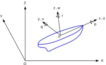
In order to describe the motion of the towing system, earth-fixed coordinate system and body-fixed coordinate systems are defined as shown in Fig. 1.
x , u
X Y
Z
o
O
p r
q z , w y , v
(a) Earth-fixed and tug and towed barge-fixed coordinates
xj, uj yj,vj
zj,wj oj
Element j qj
rj
(b) Towline element-fixed coordinate Fig. 1 Coordinate systems
Body-fixed coordinate systems are redefined as the tugboat-fixed, the towed barge-fixed, and the element of towline-fixed coordinate systems. As stated above, towline is divided as many elements and those are dealt with independent bodies and connected at the joint point.
Therefore, every element of the towline has its body-fixed coordinate system. The linear displacement is represented in the earth-fixed frame denoted by O-XYZ, while the equations of motion of the components of the towing system are described in the body-fixed frames denoted by o-xyz. External force and moment acting on a body component can be more easily described in the body-fixed frame than the earth-fixed frame. The origin of the body-fixed frame of the tugboat and the towed barge is the cross point of the longitudinal center line, the water line, and the midship section, and the direction of the
positive z axis is upward. Also, the center of the element of the towline is the centroid of the element volume, and its x-axis is positive forward and its z-axis is positive upward. The subscript in Fig.1(b) is the index of the element of the towline.
2.2 Towline
As shown in Fig. 2, towline is divided into N elements.
The forward end position of the zero element is attached at the towing point in the tugboat, and the afterward end position of the N element is attached at the towed point on the barge. Adjacent elements are connected by the spring and the damper, and those are freely moved depending on the force balance.
Element j
Element j-1 Joint j Joint j+1 Element j+1
Element 0 Joint 0 Tug
Element N-1 Joint N
Barge
Fig. 2 Configuration of the towing system (Yoon, 2012)
In order to describe the five degrees of freedom equations of motion of the element of the towline except roll, we assumed that the shape of each element is a cylinder of which sectional mass is uniformly distributed.
Fig. 3 depicts the force components acting on the j-th element, and the equations of motion presented by vector-matrix form is as follows;
′
, (1) where, : mass of the element
: added mass of the element
′ : rate of the velocity components
: Coriolis force of the element
: Coriolis force of the added mass
: drag due to enclosing fluid
: material damping of the element
: hydrodynamic force
: buoyancy
: weight
: tension
and, the underbar in Eq.(1) represents vector.
The detailed models of the force components acting on an element of towline are referred to Yoon(2012) and only the typical models are summarized again in this paper.
The x-directional added mass is assumed as zero and the y and z-directional added masses and the added mass moments of inertia are the same as the full cylinder of
which density is the same as the enclosed fluid. Coriolis force of the added mass can be modeled by using the added mass model mentioned before and the relation between inertial coordinate and non-inertial coordinate like element-fixed coordinate.
Drag force is simply modeled using axial and side drag coefficients and the square velocity component for each direction. Lift force and the moment due to hydrodynamic damping force were neglected following the assumption that the drag is much larger than the lift.
Impact force due to water entry of the element was simply modeled using the time changing rate of the added mass during entry. And, buoyancy was modeled as same as the weight of the element depending on the vertical position of the center of the element.
Material damping force is included in order for the deformation of the towline which will be represented by the element’s attitude to be calculated stably and reasonably even though the stiffness of the element is large. For this reason, it might be difficult to determine the correct values, and it should be determined empirically after comparing with the sample test result of the towline.
In this paper, we assumed that the y and z directional material damping coefficients are one tenth of the x-directional one, and the standard damping ratios of y-direction is 0.5. The real damping coefficients are calculated considering the maximum tension of the element provided by the maker of the towline.
Finally, tension, which acts on the forward and afterward joint points of the each element, is modeled by multiplying the stiffness into the distance(
) at the joint points of adjacent elements.
is updated as time marching and tension of the j-th afterward joint point which is the same magnitude but the opposite direction at the j+1-th forward joint point of the j+1-th element can be calculated. When the distance between the center of the j-th element and the forward joint point of the j+1-th element is less than the half of the length, tension will not be acted, and modeled that its value should be zero logically.
2.3 Tugboat
Tugboat dynamics was modeled based on Newton’s second law with respect to the tug–fixed coordinate as shown in Fig.1(a). In general, since the tugboat is smaller than the towed barge in size, it might be easily influenced by the environment such as wave, and current. For this reason, the six degrees of freedom motion of a tugboat were considered.
If the notations of the motion and the force are defined as the same as the ones in Eq.(1), the equations of motion
of tugboat are as follows;
′
(2)
where,
and
are thrust and rudder force respectively, and subscripts wave, and current are environmental forces due to those names.
In Eq.(2), velocity vector consists of surge, sway, heave, roll, pitch and yaw velocity. Buoyancy is calculated considering the submerged volume which will be changed at every time step. Hydrodynamic force is updated by mathematical polynomial model depending on the motions and the hydrodynamic coefficients determined by the empirical formulas. Wave force is calculated as the radiation force determined by convolution integral of the motion velocity and its impulse response function and Froude- Krylov force(Newman, 1977). Current effect is considered as the relative velocity to current velocity when the hydrodynamic force is calculated(Fossen, 1994). Finally, the magnitude of tension is the same as the one of the magnitude of tension at the forward position of the 0-th element of the towline, and the direction is opposite each other.
2.4 Towed barge
As assumed earlier, the towed barge is not easily influenced by the environmental condition because of its box-type shape. For this reason, it is proper that its dynamics was considered only for three degrees of freedom motion in the horizontal plane. Since the first-order wave force exerts relatively high oscillation on the floating body, it can be neglected in case of the towed barge. Current which influence on the slow-varying drifting of the barge was considered using the same methods in case of tugboat.
The towed barge’s three degrees of freedom equations of motion are as follows;
′
(3)
where, velocity vector components are only surge, sway and yaw velocities, and weight and buoyancy is always balanced because attitude is not changed for all time under the above assumption.
3. Simulation
3.1 Towing system
The typical specifications of the towing system consisting of a tugboat, a towed barge, and a towline used in this paper are listed in Tables 1~2. Towline was 115 m
in length which should be over 90 m to satisfy the regulation for a towing system running in the sea along the coast(KR, 1999). It was divided into 11 elements and the indices of the elements of the towline, the tugboat and the towed barge are defined in Fig. 3.
Table 1 Principal dimensions of the tugboat and the towed barge
Item Value
Tug Barge
Length overall (m) 20.0 48.0
Breadth (m) 4.30 15.0
Depth (m) 1.99 3.0
Draft (m) 1.02 1.0
Displacement (ton) 41.7 626.4
x of towing point (m) 2.0 24.0
z of towing point (m) 1.0 3.0
Table 2 Principal dimensions of the towline
Item Value
Total length (m) 115.0
Diameter (m) 0.05
Weight per unit length (kgf/m) 1.725 Max. tensile intensity (ton) 16.0
4 5 6 7 8 9
3 2 1
0 10
L=115m
Element
Barge
l=10.45m Tug
Z
0
Fig. 3 Configuration of the elements of the towline
Hydrodynamic coefficients were obtained using Kijima's empirical formulae(Kijima et al, 1990) which are valid for a conventional ship. For this reason, the barge might be more stable than the conventional one without skeg. In order to confirm the simulation program and identify the characteristics of the towing system's maneuverability, various simulations were carried out following the scenarios listed in Table 3. The initial condition for all scenarios, which a tugboat and a towed barge are at the same position and the tugboat accelerates after simulation starts, are common.
Table 3 Simulation scenarios
Class Scenario Remarks
Calm sea
Straight running Acc. included Course changing 45˚ for port
10-10 Zig-zag Tugboat
35 Stbd turn Tugboat
Disturbed sea
Beam sea Sea state 2
Side current 0.5 knots
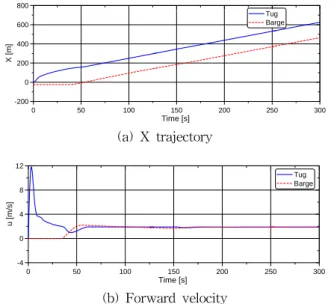
3.2 Straight running
As the simplest condition, straightly running was simulated in order that the coupled dynamics of the towing system established in this paper works correctly. Fig. 4
0 50 100 150 200 250 300
Time [s]
-200 0 200 400 600 800
X [m]
Tug Barge
(a) X trajectory
0 50 100 150 200 250 300
Time [s]
-4 0 4 8 12
u [m/s]
Tug Barge
(b) Forward velocity
Fig. 4 Simulation results of the tugboat and the barge when straight running
0 50 100 150 200 250 300
Time [s]
0 200 400 600 800
X [m]
Element 0 Element 5 Element10
(a) X trajectory
0 50 100 150 200 250 300
Time [s]
0 1 2 3
Z [m]
Element 0 Element 5 Element10
(b) Z trajectory
0 50 100 150 200 250 300
Time [s]
-4 0 4 8 12 16
θ [degree]
Element 0 Element 5 Element10
(c) Pitch angle
Fig. 5 Simulation results of the elements of the towline when straight running
shows the X trajectories and forward velocities of the tugboat and the towed barge, and Fig. 5 shows the X and Z trajectories and the pitch angles of the 0, 5 and 10-th elements of the towline.
As shown in Fig. 4.(a), the distance between the tugboat and the towed barge keeps well about 115 m which is the original towline length. Tug is accelerated freely before it runs the distance of an element length of towline, and then it is decelerated because towline pulls the tugboat as depicted in Fig. 4(b). In Fig. 5, after about 40 seconds, the tension starts to act on the barge, and the 10-th element becomes tight, then the barge’s inertia and towline element’s restoring force increase. Such a similar situation occurs again since around 145 seconds and the barge goes to steady state because there is not any restoring force acting on the barge.
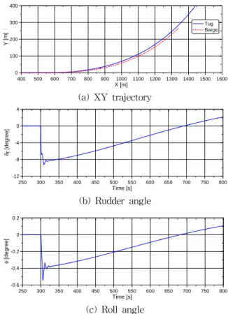
3.3 Course changing in calm sea
As the more complex case than the previous straight running, the changing course to 45˚ port side was simulated. The detailed scenario was that the tugboat runs straightly for 300 seconds and then changes course following the command of PD controlled autopilot. Fig. 6 shows XY trajectories of the tugboat and the towed barge, and rudder angle and roll angle of the tugboat. Positive rudder angle makes the heading of a tugboat turn starboard and positive roll means to incline starboard side.
Fig. 7 shows XY trajectories, yaw angles and pitch angles of several elements of the towline.
As shown in Figs. 6~7.(a), the towing system changes the preselected course well. Roll of the tugboat occurs largely inward when it starts to change its course and its time series are very similar to the ones of rudder angle. It means that roll angle of the tugboat is related to the rudder force as well as the tension from the barge because the towing point of the towed barge is higher than the tugboat as listed in Table 1.
3.4 10-10 Zig-zag
Figs. 8 and 10 show the simulation results of the 10-10 zig-zag test of the tugboat. Before the zig-zag test starts, the towing system keeps straight running for 300 seconds in order to be steady state.
As shown in Fig. 8, the overshoot yaw angle is very small because the tension due to barge prevents changing course, and after opposite execution of the rudder angle, it helps the tugboat change opposite direction. The changing pattern of the heading angles of tugboat and towed barge are similar to the sea trial case of the conventional different tugboat and the towed barge as shown in Fig.
400 500 600 700 800 900 1000 1100 1200 1300 1400 1500 1600 X [m]
0 100 200 300 400
Y [m]
Tug Barge
(a) XY trajectory
250 300 350 400 450 500 550 600 650 700 750 800
Time [s]
-12 -8 -4 0 4
δ r [degree]
(b) Rudder angle
250 300 350 400 450 500 550 600 650 700 750 800
Time [s]
-0.6 -0.4 -0.2 0 0.2
φ [degree]
(c) Roll angle
Fig. 6 Simulation results of the tugboat and the barge when course changing
400 500 600 700 800 900 1000 1100 1200 1300 1400 1500 1600 X [m]
0 100 200 300 400
Y [m] Element 0
Element 5 Element10
(a) XY trajectory
250 300 350 400 450 500 550 600 650 700 750 800
Time [s]
0 20 40 60
ψ [degree]
Element 0 Element 5 Element10
(b) Yaw angle
250 300 350 400 450 500 550 600 650 700 750 800
Time [s]
0.0 0.4 0.8 1.2 1.6 2.0
θ [degree]
Element 0 Element 5 Element10
(c) Pitch angle
Fig. 7 Simulation results of the elements of the towline when course changing
9(Yun et al, 2012). Fig. 10 shows that the element near the tugboat responds faster than the one near the towed barge.
However, higher oscillated motion occurs in the element near the tugboat because of the restoring force of the elements of the towline.
500 1000 1500 2000 2500 3000 3500
X [m]
-100 -50 0 50 100
Y [m]
Tug Barge
(a) XY trajectory
200 400 600 800 1000 1200 1400 1600 1800
Time [s]
-15 -10 -5 0 5 10 15
ψ [degree]
Tug Barge
(b) Yaw angle
200 400 600 800 1000 1200 1400 1600 1800
Time [s]
-12 -8 -4 0 4 8 12
δ r [degree]
(c) Rudder angle
Fig. 8 Simulation results of the tugboat and the barge in case of 10-10 zig-zag test
[x-axis : sec. | y-axis : Deg.]
Fig. 9 Sea trial result of the tugboat and the towed barge in case of 10-10 zig-zag test(Yun et al, 2012)
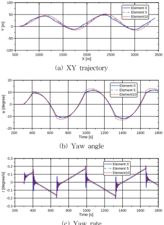
3.5 35 starboard turn
Figs. 11~12 show the simulation results of the towing system when it carries out the 35º starboard turning circle
500 1000 1500 2000 2500 3000 3500
X [m]
-100 -50 0 50 100
Y [m]
Element 0 Element 5 Element10
(a) XY trajectory
200 400 600 800 1000 1200 1400 1600 1800
Time [s]
-20 -10 0 10 20
ψ [degree]
Element 0 Element 5 Element10
(b) Yaw angle
200 400 600 800 1000 1200 1400 1600 1800
Time [s]
-0.3 -0.2 -0.1 0 0.1 0.2 0.3
r [degree/s]
Element 0 Element 5 Element10
(c) Yaw rate
Fig. 10 Simulation results of the elements of the towline in case of 10-10 zig-zag test
test. The test starts after straightly running for 300 seconds which is the same as the case of the zig-zag test.
As shown in XY trajectories in Figs. 11~12, the element near the tugboat has large turning diameter. The surge velocities are oscillated within 0.1 knots. Also, low frequency motion of the elements far from the tugboat lasts for long time until the towing system becomes steady.
3.6 Course changing at beam sea
Figs. 13~14 show the simulation results of the towing system which changes the course in beam waves of which direction is from port to starboard. The scenarios after this section are all the same as the course changing in calm sea which changes the course of 45˚ port direction. Wave was assumed as the long-crested irregular wave composed of 10 regular wave components divided using the ITTC wave spectrum(Lewis, 1989).
XY trajectories and yaw angle are similar to the case of changing course in calm sea except that the highly oscillation motion occurs due to the first-order wave force.
0 -200 -400 -600 -800 -1000 Y [m]
0 200 400 600 800 1000
X [m]
Tug Barge
(a) XY trajectory
200 400 600 800 1000 1200 1400 1600 1800
Time [s]
-1.5 -1 -0.5 0 0.5
r [degree/s]
Tug Barge
(b) Yaw rate
200 400 600 800 1000 1200 1400 1600 1800
Time [s]
1.84 1.88 1.92 1.96 2.00
u [m/s]
Tug Barge
(c) Surge velocity
Fig. 11 Simulation results of the tugboat and the barge in case of 35 stbd turn
0 -200 -400 -600 -800 -1000
Y [m]
0 200 400 600 800 1000
X [m]
Element 0 Element 5 Element10
(a) XY trajectory
200 400 600 800 1000 1200 1400 1600 1800
Time [s]
-0.4 -0.3 -0.2 -0.1 0 0.1
r [degree/s]
Element 0 Element 5 Element10
(b) Yaw rate
Fig. 12 Simulation results of the elements of the towline in case of 35 stbd turn
400 500 600 700 800 900 1000 1100 1200 1300 1400 1500 X [m]
0 100 200 300 400 500
Y [m]
Tug Barge
(a) XY trajectory
250 300 350 400 450 500 550 600 650 700 750 800
Time [s]
0 10 20 30 40 50
ψ [degree]
Tug Barge
(b) Yaw angle
Fig. 13 Simulation results of the tugboat and the barge when course changing at beam sea
250 300 350 400 450 500 550 600 650 700 750 800
Time [s]
0 10 20 30 40 50
ψ [degree]
Element 0 Element 5 Element10
Fig. 14 Yaw angles of the elements of the towline when course changing at beam sea
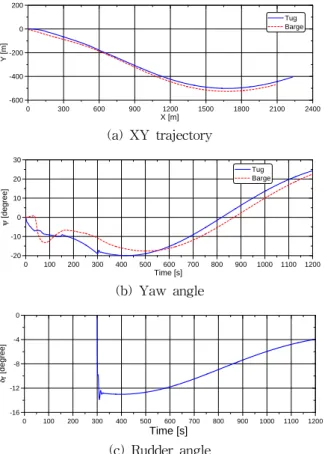
3.7 Course changing in side current
Figs. 15~16 show the simulation results of the towing system which changes the course in side current. Current flows from port to starboard.
Since the stable yaw angle is -90˚, the towing system changes the course negatively before the positive yawing moment has been developed. Fig. 15(c) shows that the rudder deflection calculated by the autopilot is larger than the case of course change in calm sea depicted in Fig.
6(b). When the tension acts on the barge, highly oscillating motion occurs and after a little time passed, the towing system changes the course positively.
7. Conclusion
The coupled dynamics of the towing system which consists of a tugboat, a towed barge, and a towline was established based on the finite element model of the towline and Newton’s second law. In order to confirm the established dynamic model, various maneuvering scenarios in calm sea and at real sea where wave and current exist, were simulated.
0 300 600 900 1200 1500 1800 2100 2400 X [m]
-600 -400 -200 0 200
Y [m]
Tug Barge
(a) XY trajectory
0 100 200 300 400 500 600 700 800 900 1000 1100 1200 Time [s]
-20 -10 0 10 20 30
ψ [degree]
Tug Barge
(b) Yaw angle
0 100 200 300 400 500 600 700 800 900 1000 1100 1200
Time [s]
-16 -12 -8 -4 0
δ r [degree]
(c) Rudder angle
Fig. 15 Simulation results of the tugboat and the barge when course changing in side current
0 100 200 300 400 500 600 700 800 900 1000 1100 1200 Time [s]
-30 -20 -10 0 10 20 30
ψ [degree]
Element 0 Element 5 Element10
Fig. 16 Yaw angles of the elements of the towline when course changing in side current
As the result, the dynamic model can estimate the maneuverability of the towing system properly in common sense. In the future, if those simulation results compare with the ones of the real sea trial or free running model test, and then the dynamic model is improved, it can be widely used for predicting the towing performance by towing simulation and for educating tug-handling mate by using simulators.
Acknowledgements
This research was financially supported by "Changwon National University in 2011~2012" and the project
“Development of simulation technique of the towing system considering the material characteristics of the towing line”,
which was sponsored by Maritime & Ocean Engineering Research Institute, KORDI.
References
[1] Berteaux, H. O. (1976), Buoy Engineering, John Wiley
& Sons, pp. 97-134
[2] Fossen, T. I. (1994), Guidance and Control of Ocean Vehicles, John Wiley & Sons, pp. 84-90
[3] Kijima, K., Nakiri, Y., Tsutsui, Y., Matsunaga, M.
(1990), "Prediction Method of Ship Manoeuvrability in Deep and Shallow Water", MARSIM & ICSM Proceedings, Japan, pp. 311-319
[4] Korean Register (1999), Regulation for the towed vessel, RB-12-01, Korean Register, p. 5
[5] Lewis, E. V. (1989), Principles of Naval Architecture 2nd Rev. Volume III - Motions in Waves and Controllability, The Society of Naval Architects and Marine Engineers, pp. 26-40
[6] Newman, J. N. (1977), Marine Hydrodynamics, The MIT Press, pp. 307-311
[7] Yoon, H. K., Lee, G. J., and Kim, S. Y. (2011), “Causal Analysis of a Tugboat Capsizing based on a Dynamical Simulation”, International Journal of Ocean System Engineering, Vol. 1, No. 4, pp. 211-221 [8] Yoon, H. K., Lee, H. S., Park, J. K., and Kim, Y. G.
(2012), “Dynamic Modeling and Simulation of a Towing Rope using Multiple Finite Element Method”, Journal of Navigation and Port Research, Vol. 36, No.
5, pp. 339-347
[9] You, K. P. (2011), “A Study on the Navigation Rules in the Oil Spill Accident of M/T Hebei Spirit”, Master’s Thesis, Dept. of Maritime Police Law, Mokpo Maritime University, pp. 1-15
[10] Yun, K. H., Kim, Y. G, Yeo, D. J. (2012),
"Maneuvering Characteristics of Tug-Barge from the Results of Sea Trial Test", Journal of Navigation and Port Research, Vol. 36, No. 1, pp. 15-20
Received 2 May 2012 Revised 28 May 2012 Accepted 20 June 2012
![Fig. 11 Simulation results of the tugboat and the barge in case of 35 stbd turn 0 -200 -400 -600 -800 -1000 Y [m]02004006008001000X [m] Element 0Element 5 Element10 (a) XY trajectory 200 400 600 800 1000 1200 1400 1600 1800 Time [s]-0.4-0.](https://thumb-ap.123doks.com/thumbv2/123dokinfo/5189407.350829/7.892.475.803.116.420/simulation-results-tugboat-barge-element-element-element-trajectory.webp)