1. 서 론
현재 환경문제 및 에너지 위기 대책으로서 열 효율이 높고 안전할 뿐 아니라 공해물질이 거의 발생하지 않는 청정연료인 천연가스의 사용이 세 계적으로 급증하고 있다 따라서 높은 효율을 가. 진 청정 에너지의 장점 때문에 천연가스의 사용 은 세계적으로 꾸준히 증가하는 추세이며 우리, 나라도 천연가스가 도입된 이래 급격한 경제규모
의 증대에 힘입어 사용량이 크게 증가하고 있다.
저장탱크는 가 가진 저온 환경에서도
LNG LNG
우수한 강도와 인성을 가진 저온용 재료를 내벽 재료로 사용 한다 현재까지 가장 널리 사용되어. 지고 있는 재료는 9% Ni강이며 본 재료는 우수, 한 저온 인성을 바탕으로 지상형 LNG 저장탱크 의 내조로서 전 세계에 널리 사용되어지고 있다.
저장탱크의 구조물은 대부분 용접구조물로 LNG
구성되어지며 온도에 따라서 내구성에도 영향을, 미치게 된다 용접시에 발생되는 용접부의 결함. 은 대표적으로 기공 언더컷 불연속적인 이음부, , 등의 현상이 유발시켜서 구조물의 피로강도를 크 게 감소시키고 있다. 9% Ni강의 경우 용접봉은 모재의 성분과 동일한 성분계가 있지만 대부분의 경우 저온에서 더욱 안정한 오스테나이트계열의
고니켈계가 사용되고 있다 강의 기존 열처
강의 피로균열진전거동에 관한 연구 9% Ni
심규택
*
․ 김재훈†
․ 이관희**
․ 안병욱**
․ 김영균***
A Study on the Fatigue Crack Growth Behavior of 9% Ni Steels
Kyue-Taek Shim, Jae-Hoon Kim, Kwan-Hee Lee, Byung-Wook Ahn, Young-Kyun Kim
Key Words:
9% Ni Steel(9% 니켈강), Fatigue crack growth(피로균열진전속도),하중비 용접재
Load ratio( ), Welded metal( ).
Abstract
This study is to evaluate the fatigue crack growth characteristics for base metals and welded metal of 9% Ni steels. Since this material has very excellent fracture toughness at low temperature, it has been widely used for inner walls of LNG storage tank. These materials to compare fatigue crack growth (FCG) behaviour are treated with heat by the method of quenching and tempering (QT), and quenching, lamellarizing and tempering (QLT). FCG tests using compact temsion (CT) specimen under stress ratio R=0.1, 0.5, and constant load are carried out. K-increasing tests are conducted by the standard test method described in ASTM E 647. To investigate the effect of welded metal on the crack growth rate, the locations of notch tip were chosen at the center of welded metal and heat affected zone (HAZ). Form the results, FCG rate has almost same tendency according to stress ratio, base and welded metal, the locations of welded metal. FCG rate of welded metal is somewhat faster than base metal. Also scanning electron microscope (SEM) is used to observe the striation of the fractured surface after fatigue crack tests.
† 회원 충남대학교 기계설계공학과, E-mail : [email protected]
TEL : (042)821-7628 FAX : (042)822-7366
* 회원 충남대학교 기계설계학과,
** 한밭대학교 기계공학과
*** 한국가스공사 연구개발원
대한기계학회 2008년도 추계학술대회 논문집
리 방법과는 다른 QLT (quenching, lamellarizing 열처리 공정을 채택하였다 단 열
and tempering) . 3
처리 공정인 QLT 열처리는 담금질 열처리 처리 와 뜨임 열처리 (quenching trcatment, Q )
처리 중간에
(quenching treatment, T ) AC1과 AC3 사 이의 페라이트와 오스테나이트의 2상 영역으로 가열후 공냉시키는 층상화 열처리 (lamellarizing 처리 를 추가로 행하여 열적으로 안정 treatment, L )
한 잔류오스테나이트 함량의 증가와 결정립 크기 의 미세화를 통하여 저온 인성의 증가를 얻는 열 처리방법이다.(1) 이런 재료를 응력확대계수 범위
△Kth (near-threshold stress intensity factor range)는 피로균열진전 거동에서 중요한 의의를 갖고 있 다. ASTM E 647 에서는 하한계 응력확대 계수범 위 ( K△ th)를 구하는 방법으로써 K-증가실험법을 제안하고 있다 따라서 본 연구에는. K-증가 실험 법으로 9% Ni 강의 용접재의 용접부에 대한 피 로균열 진전시험을 수행하여 하한계 응력확대 계 수 범위를 결정 하였고 같은 시험조건과 시험법, 으로 피로균열진전 거동 및 피로 수명에 대해 고 찰하였다.
2. 실험방법
사용재료 및 용접 2.1
실험에 사용된 재료는 9% Ni강은 국내 LNG 저장탱크에 공급되는 재료의 강과 동일한 강이 다. QT와 QLT를 사용하였으며, 판 두께는
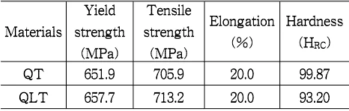
이다 화학 성분과 기계적 성질을
12.7mm . Table
과 에서 나타내었으며 규
1 Table 2 , ASTM A 553 격을 따른다.(2,3)
Table 1
Chemical compositions of 9% Ni steel (wt%)Table 2 Mechanical property of 9% Ni steel.
시험에 사용된 재료는 모재에 대하여 SMAW 용접을 이용하였으며 (shielded metal arc welding) , 용접 공정의 경우 입열량이 낮기 때문에 균열에 대한 문제가 적어 Inconel계 용접봉을 사용하였 다 따라서 사용된 용접봉은. Inconel계 용접봉인 AWS 511 E NiCrFe-4계의 YAWATA WELD
이 사용하였다 실제 저장탱크 건설 시
B(M) . LNG
의 용접부와 동일한 조건으로 행하였다 용접자. 세는 전자세로 실시하였다. Fig. 1은 시험에 사용 된 모재에 대해 용접한 X-groove의 형상이며 용, 접 후 액체침투탐상검사 및 X-선 투과검사를 통 하여 용접결함이 없음을 확인하였다.
Fig. 1 Schematic view of X-groove preparation
Fig. 2 Macrostructure of the 9% Ni welded metal
에서는 용접부 중 열영향부Fig. 2 HAZ (heat
는 용접공정 중 발생되는 열에 의해 affected zone)
다양한 조직으로 변태되어 모재와는 완전히 다른 특성을 나타낸다. Fig. 2에 대해서 Fag. 3에서는 로크웰 경도기(Rockweel hardness)를 사용하여 HRB를 측정하였다 그 값은 용접부에서는. 83~90 HRB를 보이고 있다 특히 용접 열영향부는 후속. 용접에 의한 tempering 효과에 의하여 경도값이 높아지므로 이점을 유의 하여야한다. 따라서 부분에서는 경도값이 높은 결과를 것을 볼 HAZ
수 있다.
0 5 10 15 20 25 30 80
90 100 110 120 130
R o ck w e ll H a rd n e ss (H
RB)
Distance (mm)
Upper Middle lower Average
Fig. 3 Distributions of Rockwell hardness
measurement실험장치 및 실험방법 2.2
본 시험에 사용된 피로 시험기는 MTS사의 유압식 만능시험기로서 최대 용량은
MTS 810 10
ton이다. 균열 길이는 Microscope로 앞 ‧ 뒷면을 측정하였으며 전체 데이터값의 평균값을 사용하, 였다 시험 조건은 응력비. R=0.1, 0.5의 인장 인장- 하중형태로 모재와 용접재를 같은 조건으로 수행 하였다 시험 주파수는. 6Hz, 8Hz를 사용하였으며, 파형은 정현파(sine wave)로 시험하였다. 응력비
의 하중비 로 실험 하였
R=0.1 1200~120 kgf, 6Hz
고, R=0.5의 하중비 1500~150 kgf, 8Hz로 실험을 하였다 시험편의 예비균열을 노치로부터. 1.0~1.3
까지 주었다 재료의 노치는 와 같이
mm . Fig. 5
가공하였다.
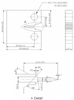
Fig. 4 Notch location
용접재료는 HAZ 부분의 피로균열 진전속도를 시험하기위해 노치를 Fig. 4와 같이 용착금속의 경계부에서 1~1.5 mm 떨어진 곳에 노치를 주어 시험을 실시하였다 피로 시험편은. ASTM E 647,
와 같이 가공하였으며 노치부는 와이어 방전가
5 ,
공 (EDM : Electric discharge machining)을 사용하 여 가공하였다.
Fig. 5 Configuration and dimensions of specimen
결과 및 고찰 3.
3.1 응력비 영향
본 실험은 응력비 R=0.1, 0.5로 실험 하였으며,
△ 는
K
ASTM E 647에 명시되어있는 조건으로 식 에서 계산하였다(1) .(4)
∆
∆
(1)
재료의 열처리는 실험의 차이를 보기위하여, 와 를 한 열처리 재료를 모재와 용접재를 QT QLT
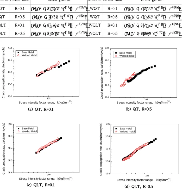
실험하여 피로균열 진전시험을 평가 하였다 일. 반적으로 균열을 가진 재료의 피로균열진전거동 은 균열진전속도 (da/dN 와 선형탄성 파괴역학 파) 라미터인 응력확대계수범위 ( K△ 의 상관식으로) 표현된다. Paris는 피로균열진전의 중간영역에 대 하여 식 (2)와 같은 피로균열진전속도와 응력확대
계수범위의 관계를 제안하였다.(5)
∆ (2)
여기서 c 와 m 은 재료상수이다 이들의 관계. 로부터 얻어진 c 와 m은 Table 3에 정리하였다.
100 1E-6
1E-5 1E-4 1E-3 0.01
Stress intensity factor range, ∆k(kgf/mm3/2)
Crack propagation rate, da/dN(mm/cycle)
Base Metal Welded Metal
100 1E-6
1E-5 1E-4 1E-3 0.01
Stress intensity factor range, ∆k(kgf/mm3/2)
Crack propagation rate, da/dN(mm/cycle)
Base Metal Welded Metal
Fig. 6 da/dN-
△K
of base and welded metals for QT and QLT specimens.Fig. 6
. K
△ da/dN (R)
.
.
100 1E-6
1E-5 1E-4 1E-3 0.01
Stress intensity factor range,
∆k(kgf/mm
3/2)
C rack pro paga ti on rate, da /dN (m m /c y c le)
Base metal Welded metal
100 1E-6
1E-5 1E-4 1E-3 0.01
Stress intensity factor range,
∆k(kgf/mm
3/2)
Crack prop ag ation rate, da/dN(m m /cy cle )
Base metal Welded metal
Table 3 Results of material constants C and m obtained from Paris equation
× ∆ × ∆
× ∆ × ∆
× ∆ × ∆
× ∆ × ∆
, , , (blow hole),
. Fig. 7은 피로균열진전시험을 통하여 실시한 모재와 용접재에 대한 da/dN- K△ 를 나타 낸 것이다.
100 1E-6
1E-5 1E-4 1E-3 0.01
Crack propagation rate, da/dN(mm/cycle)
Stress intensity factor range, ∆k(kgf/mm3/2) Base QT R=0.1 Base QT R=0.5 Base QLT R=0.1 Base QLT R=0.5 Welded QT R=0.1 Welded QT R=0.5 Welded QLT R=0.1 Welded QLT R=0.5
Fig. 7 da/dN-
△K
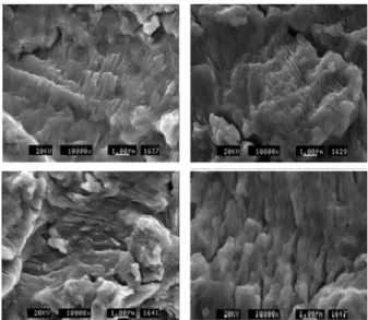
of all specimens for 9% Ni steel파단면의 형상 3.2
Fig. 8, 9
R=0.1, 0.5 R=0.1, 0.5
Topcon MS-500 .
SEM
. 1.0
~ 1.5 mm ,
2.33 x 10⁻⁵ .
Fig. 8 Fatigue fracture surfaces of base and welded
Fig. 9 Fatigue fracture surfaces of base and welded metals (QLT)
4. 결 론
1)
,
. 2)
HAZ .
3) QT QLT
8Hz 6Hz .
후 기
참고문헌
1. J-I. Jang, J-B. Ju, B-W. Lee, D. Kwon, W-S, Kim, 2003, “Effects of microstructural change on fracture characteristics in coarsegrained heat-affected zones of QLT-processed 9% Ni steel”
Materials Science and Engineering A340 68~79
2. ASTM A553, 2005, Annual Book ofASTM-Standards Section 1, Iron and Steel Products
3. ASTM A353, 2006, Standard Test Methods for Chemical Analysis of Stainless, Heat-Resisting, Maraging, and Other Similar Chromium-Nickel-Lron Alloys
4. ASTM E647, 1999, "ASTM E647: Standard Test Method for Measurement of Fatigue Crack Growth Rates", In Annual Book of ASTM Standards, Vol.
03.01, ASTM-American Society for Testing and Materials, West Conshohocken, PA, 591-630 5. Paris PC, 1961, “Gomez MP, Anderson WE. A
rational analytic theory of fatigue. The Trend Engng”, 13:9-14
6. D.P. Fairchild, 1990, “Fatigue and Fracture Testing of Weldments”, ASTM STP 1058,
American Society for Testing and Materials,
Philadelphia, pp. 117-1417. Korea gas Corporation Homepage :
www.kogas.or.kr
8. Japan Gas Association Committee, 1979,
"Recommended Practice for LNG Inground Storage"
9. J-H. Baek. Y-P. Kim, W-S. Kim, Y-T. Kho, 2001, “Fracture toughness and fatigue crack growth properties of the base metal and weld metal of a type 304 stainless steel pipeline for LNG transmission”,