* 전북대학교 기계시스템공학부 ([email protected]) 주소: 561-756 전라북도 전주시 덕진구 1가 664-14
+ 전북대학교 정밀기계공학과
++ 우석대학교 기계자동차공학과
+++ 송원대학교 기계자동차공학과
준정적 축 압축하중을 받는 Al/CFRP/GFRP 혼성부재의 에너지흡수 특성
김선규*, 허 욱+, 임광희++, 정종안+++
(Manuscript received: Jun, 27, 2012 / Revised: Jul, 11, 2012 / Accepted: Jul, 23, 2012)
Energy Absorption Characteristics of the Al/CFRP/GFRP Hybrid Member under Quasi-static Axial Compressive Load
Sun-Kyu Kim*, Uk Heo+, Kwang-Hee Im++, Jong-An Jung+++
Abstract
This study concentrates the effect of hybridisation on the collapse mode and energy absorption for composite cylinders.
The static collapse behavior of laminated(Al/CFRP/GFRP) circular-cylindrical composite shell under quasi-static axial compressive load has been investigated experimentally. Eight different hybrids of laminated(Al/CFRP/GFRP) circular-cylindrical composite shell were fabricated by autoclave. Eight types of composites were tested, namely, Al/carbon fiber/epoxy, Al/glass fiber/epoxy, Al/carbon-carbon-glass/epoxy, Al/carbon-glass-carbon/epoxy, Al/carbon-glass-glass/epoxy, Al/glass-glass-carbon/epoxy, Al/glass-carbon-glass/epoxy and Al/glass-carbon-carbon/epoxy. Collpase modes were highly dominated by the effect of hybridisation. The results also showed that the hybrid member with material sequence of Al-glass-carbon-carbon/epoxy exhibited good energy absorption capability.
Key Words : CFRP(탄소섬유강화복합재), GFRP(유리섬유강화복합재), Collapse mode(압궤모드), Energy absorption(에너지흡수), Quasi-static axial compressive load(준정적 축 압축하중)
1. 서 론
최근 자동차에 적용되는 핵심기술의 개발은 탑승자의 안전성 확보, 연비 개선을 위한 경량화 그리고 환경오염 억제를 위한 친환경성 및 재활용 가능한 소재 개발로 집약될 수 있다. 승객 및 보행자의 안정성 관련 법규가 지속적으로 강화되고, 무엇보 다도 해마다 상승하는 유가의 영향으로 고연비 차량 개발 경쟁 이 심화되었으며, ‘친환경’이라는 새로운 가치와 미래자동차
적용을 위한 신기술 개발이라는 과제가 자동차산업에 있어 비 중이 커져 가고 있다. 미래자동차의 안전성, 친환경성을 구현하 기 위해서는 지금의 소재보다 훨씬 더 가볍고 고강도의 신소재 의 개발이 필수적이다. 가장 가까운 시일 내로 차량 적용이 증 대될 소재는 탄소섬유강화 복합재료이다(1).
차량의 중량은 안전성과 편의성에 대한 요구 증대로 차량에 장착되는 부품의 수가 늘어남에 따라 증가하는 추세에 있다.
차체의 안전도 향상을 위해 사용되는 고강도 부재의 적용으로
Table 1 Material properties of the CFRP prepreg sheet and aluminum
Aluminum Fiber (Carbon)
Resin (Epoxy
#2500)
Prepreg sheet Density
[kg/m3] 2,680 1.8×10³ 1.2×10³ 1.55×10³
Poisson's ratio 0.31 - - 0.36
Young's
modulus [GPa] 67.2 230 - 145
Tensile stress
[GPa] 192 4.9 - 2.468
Resin content
[%Wt] - - - 33
Table 2 Material properties of the GFRP prepreg sheet
Construction 4 shaft satin
Yarn type Warp G 75 1/0
Fill G 150 1/0
Density[count/inch] Warp 64
Fill 26
Fabric areal weigh [g/m2] 207.1
Resin content [%] 35.4
Volatile content [%] 0.99
Fig. 1 Configuration of Al/CFRP/GFRP circular member 인한 중량 증가를 상쇄하고 연비 향상을 위해 경량소재를 사용
한 차체 경량화가 추진되고 있다. 차체 부품 중 고강도를 요하는 부품은 고장력강이나 고강도 알루미늄을 사용하여 경량화하고 있다. 고장력강 및 알루미늄 외에도 마그네슘, CFRP(Carbon Fiber Reinforced Plastic) 등 경량소재를 적용하여 차체를 구 성하는 다종재료 적용기술도 함께 개발하고 있다(2).
수송기계의 안전성 향상과 연비개선을 위한 차체 구조부재의 에너지흡수 능력을 향상시키기 위해서 여러 가지 기하학적 구 조 및 복합재료, 복합재료와 이종 재료를 혼합한 혼성부재에 대한 연구가 많이 행해지고 있다(3~12).
본 연구에서는 차체 구조부재의 안전성 확보와 연비 개선을 위한 경량화에 대한 방안으로 비강도 비강성이 우수한 탄소섬 유 강화 복합재(CFRP) 및 유리섬유 강화 복합재(GFRP: Glass Fiber Reinforced Plastic)를 이용하여 알루미늄 원형 부재의 외측에 CFRP/GFRP로 감싸 강화시킨 부재를 제작한 후 적층 순서 변화에 따른 압궤특성 및 에너지흡수특성을 고찰하였다.
2. 본 론
2.1 시험편
본 연구에서는 경량화 재료인 알루미늄과 CFRP 및 GFRP를 이용하여 원형의 형상을 갖는 부재를 제작하여 시험편으로 사 용하였다.
알루미늄 부재는 시판용(제일 알루미늄) 압출파이프 6063-T5 계열로서 두께는 1.0mm이며, 외경 35mm인 원형부재이다.
CFRP 프리프레그 시트는 한국화이버(주)에서 생산한 일방향 Carbon Fiber/Epoxy Resin 프리프레그 시트(CU125NS)이다.
GFRP 프리프레그 시트는 한국화이버(주)에서 생산한 Grass Fiber/Epoxy Resin SATIN 프리프레그 시트이다. Table 1는 시험편을 제작하는데 사용된 알루미늄과 CFRP, Table 2는 GFRP 프리프레그 시트의 물성치를 나타내고 있다.
시험편은 Fig. 1과 같이 알루미늄과 CFRP 및 GFRP를 결합 한 원형 혼성부재로서 알루미늄 원형 부재의 외측에 CFRP 프 리프레그 시트와 GFRP 프리프레그 시트를 적층하였다. 프리 프레그 시트는 총 6매로 하였으며 축 방향에 대하여 GFRP는 Warp(경사)가 0°, CFRP는 섬유가 90°의 방향을 갖도록 적층 한 후 오토크레이브를 이용하여 성형하였다. 여기서 CFRP, GFRP를 적층할 때 적층순서(CCC, CCG, CGC, CGG, GGG, GGC, GCG, GCC(C와 G는 각각 CFRP, GFRP를 나타냄))를 변화시켜 적층순서 변화에 따른 압궤특성 및 에너지흡수특성 을 비교 고찰하였다.
시험편의 성형은 오토크레이브를 이용하여 챔버 내부 둘레에 위치한 히터에 의해 경화온도 130℃, 경화시간 90분으로 제작 하였다. 성형 할 때 진공펌프에 의해서 진공백 속을 10-1Pa까지
진공 시킨 후 진공백 외측은 3×10⁵Pa 가압시켜 제작하였다. 시 험편의 길이는 오일러좌굴을 일으키지 않고 실험 할 때 압궤가 반복하여 나타나는데 충분한 길이인 120mm로 하였다.
2.2 압궤실험
압궤실험은 만능재료시험기를 사용하였으며 로드셀과 엑츄 에이터 사이에 두 개의 압축지그를 평행하게 설치하고 변형속 도의 영향이 나타나지 않도록 10mm/min의 속도제어를 통하 여 균일한 축 압축하중이 가해지도록 실험을 행하였다. 시험편 제작은 실험 할 때 편심하중이 작용하지 않도록 연마가공을 통
Fig. 2 Load-displacement curve and collapse history of Al/CFRP/
GFRP/CFRP(CGC) circular member
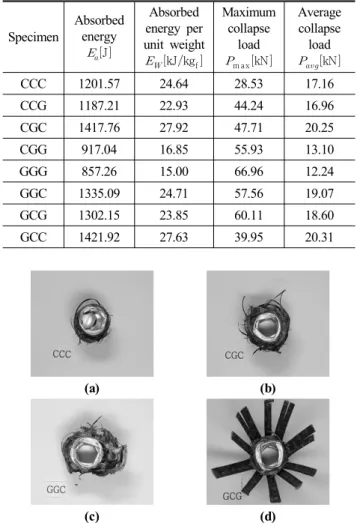
Table 3 Quasi-static axial compressive load test results for specimen according to change in the stacking sequence
Specimen
Absorbed energy
J
Absorbed energy per unit weight
kJkgf
Maximum collapse
load
m axkN
Average collapse
load
kN
CCC 1201.57 24.64 28.53 17.16
CCG 1187.21 22.93 44.24 16.96
CGC 1417.76 27.92 47.71 20.25
CGG 917.04 16.85 55.93 13.10
GGG 857.26 15.00 66.96 12.24
GGC 1335.09 24.71 57.56 19.07
GCG 1302.15 23.85 60.11 18.60
GCC 1421.92 27.63 39.95 20.31
(a) (b)
(c) (d)
Fig. 3 Collapse modes of Al/CFRP/GFRP circular member (a) compound folding mode (b)(c) compound fragmentation and folding mode (d) compound splaying and folding mode 하여 수평을 맞추고 여러 번의 예비실험을 거쳐 실험결과의 재
현성을 확보하였다. 순차적인 압궤가 주기적으로 발생하도록 전체 축 방향 길이 120mm가 70mm까지 변형되도록 변위 제 어를 통하여 압궤실험을 행하였다.
압궤실험에서 측정된 하중 및 변위에서 시간 성분을 소거하 여 얻어진 하중-변위선도의 면적을 시험편이 흡수한 에너지로 보고 하중-변위선도를 식 (1)과 같이 적분하여 시험편에 흡수 된 에너지량을 구하였다.
(1)
여기서 는 시험편에 흡수된 에너지, 은 압궤하중, 는 압궤 전의 시험편의 길이, 은 압궤 후 시험편의 길이를 나 타낸다.
경량화 차원에서 흡수에너지를 고찰하기 위하여 흡수에너지 를 시험편의 중량으로 나눈 값인 단위중량당 흡수에너지를 식 (2)와 같이 구하였다.
(2)
여기서 는 단위중량당 흡수에너지, 는 각 시험편의 중 량을 나타낸다.
Fig. 2는 적층수가 각각 6ply를 갖는 Al/CFRP/GFRP/CFRP 원형부재의 하중-변위선도 및 압궤과정을 나타냈다. 또한 압궤 실험 후의 결과 값을 Table 3에 나타냈다.
2.2.1 압궤모드
본 연구에서는 Al/CFRP/GFRP의 적층변화에 따라 준정적 축 압축실험을 행하였다.
Al 원형 부재의 압궤모드는 일반적으로 축대칭모드, 비축대 칭모드 그리고 축대칭모드와 비축대칭모드가 혼합된 압궤모드
를 이루면서 순차적으로 압궤된다(13~15). CFRP 원형 부재의 경 우는 적층각의 변화에 의해서 주로 압궤모드가 결정된다(16,17). 본 연구에서 Al/CFRP/GFRP 원형 혼성부재는 3가지 형태의 압궤모드를 보였으며, 이는 CFRP/GFRP의 적층순서에 의해서 주로 결정되었다.
Fig. 3은 Al/CFRP/GFRP 원형 혼성부재의 압궤실험 후 나 타난 압궤형상을 나타냈다. Fig. 3(a)는내부에 있는 Al 부재의 접힘 사이에 CFRP 부재가 주로 끼어들어가는 압궤모드로 혼 합 접힘모드(compound folding mode)라 정의하였고, 이는 CFRP 섬유의 적층각이 90°이기 때문에 안정적인 굽힘을 보였 다. Fig. 3 (b)(c)에서 CFRP 부재는 Fig. 3(a)와 마찬가지로 접 힘모드를 형성하므로 GFRP 부재가 내․외측으로 확장되지 못 함으로써 섬유가 파단되면서 압궤되는 모드로 혼합 파쇄 및 접 힘모드(compound fragmentation and folding mode)라 정의 하였다. Fig. 3(d)는 내측에 있는 GFRP 부재는 내․외측으로 확
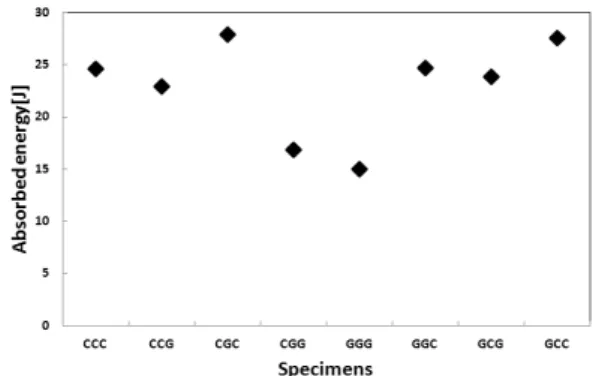
Fig. 4 Absorbed energy due to changes in the stacking sequence
Fig. 5 Absorbed energy per unit weight due to changes in the stacking sequence
장되지 못하고 섬유가 파단되면서 압궤되고, 중간에 있는 CFRP 부재는 안정적인 굽힘을 보이며, 최외측의 GFRP 부재 의 섬유가 외측으로 확장되고 파단되면서 압궤되는 모드로 혼 합 확장 및 접힘모드(compound splaying and folding mode) 라 정의하였다.
Al/CFRP/GFRP 원형 혼성부재는 CFRP 부재가 최외측에 있으면 혼합 파쇄 및 접힘모드를 보이고, GFRP 부재가 최외측 에 있으면 혼합 확장 및 접힘모드로 나타났다.
2.2.2 에너지흡수 특성
Fig. 4는 각 부재에 대한 흡수에너지 및 최대압궤하중을 나타 냈으며 Fig. 5는 경량화의 경향을 살펴보기 위해서 단위중량당 흡수에너지를 나타냈다. Fig. 4로부터 GCC 및 CGC 시험편의 경우가 가장 높은 흡수에너지 값을 나타냈으며 GGC 및 GCG, CCC 및 CCG의 순서로 나타났다. GCC 및 CGC의 시험편의 경우가 가장 높은 흡수에너지 값을 나타내는 이유는 내측에 있 는 GFRP 부재가 외측으로 확장되어 벌어지지 못하게 됨으로 써 GFRP 섬유가 파단되면서 CFRP 부재와 함께 순차적으로 접힘을 일으키면서 압궤되기 때문으로 생각된다.
그러나 Al/CFRP 원형 혼성부재의 경우는 시험편의 중앙부 분에서 국부좌굴이 발생하면서 압궤가 진행되는 것으로 보여
흡수에너지가 과소평가되었을 가능성이 있다고 생각된다. 또 한 최대 압궤하중의 경우는 적층순서에 관계없이 GFRP의 적 층수가 4ply일 때 더 높은 값을 나타냈다.
경량화의 차원에서 살펴본 단위중량당 흡수에너지는 흡수에 너지와 유사한 경향을 보이고 있다. 또한 Al/CFRP/GFRP 원 형 혼성부재에 있어서 CFRP와 GFRP의 적층변화에 따라서 에 너지흡수 특성이 변화하고 있음을 알 수 있다. 따라서 적층수 6ply 중 4ply는 CFRP 부재로, 2ply는 GFRP 부재를 사용하고 적층순서는 Al/GFRP/CFRP/CFRP나 Al/CFRP/ GFRP/CFRP 와 같이 GFRP 부재가 내측 또는 중앙에 위치하도록 제작되어 야 한다. 이는 GFRP 프리프레그시트가 직물(주자직)섬유이기 때문으로 생각된다.
3. 결 론
본 연구에서는 차체 구조부재의 안전성 확보와 연비 개선을 위한 경량화에 대한 방안으로 Al/CFRP/GFRP 원형 혼성부재 를 제작하여 축 방향 준 정적하중을 받을 때의 압궤특성을 고찰 한 결과 다음과 같은 결론을 얻었다.
(1) Al/CFRP/GFRP 원형 혼성부재는 적층순서에 따라 혼합 접힘모드(CCC), 혼합 파쇄 및 접힘모드(CGC, GGC), 혼 합 확장 및 접힘모드(GCG)로 압궤되었다.
(2) Al/CFRP/GFRP 원형 혼성부재의 흡수에너지는 GCC 및 CGC의 경우가 가장 높은 흡수에너지 값을 나타냈으며 GGC 및 GCG, CCC 및 CCG의 순서로 나타났다. 또한 단위중량당 흡수에너지도 흡수에너지와 유사한 경향을 보 였다.
(3) 적층할 때는 적층수 6ply 중 4ply는 CFRP, 2ply는 GFRP 를 사용하고 적층순서는 GFRP 부재가 내측 또는 중앙에 위치함으로써 흡수에너지가 상대적으로 높았다.
References
(1) Cho, W., 2008, “Materials and Recycling Technology for Automobile,” Auto Journal, Vol. 30, No. 4, pp.
65~75.
(2) Han, B. S., 2012, “Safety and Light Weight Technologies of Automotive Body Parts,” Auto Journal, Vol. 34, No.
4, pp. 61~63.
(3) Mahdi, E., Hamouda, A. M. S., Sahari, B. B., and Khalid, Y. A., 2003, “Effect of Hybridisation on Crushing Behaviour of Carbon/Glass Fibre/Epoxy Circular-cylindrical Shells,” Journal of Materials Processing Technology, Vol. 132, No. 1-3, pp. 49~57.
(4) Mahdi, E., Sahari, B. B., Hamouda, A. M. S., and Khalid, Y. A., 2001, “An Experimental Investigation into Crushing Behaviour of Filament-wound Laminated Cone-cone Intersection Composite Shell,” Composite Structures, Vol. 51, No. 3, pp. 211~219.
(5) Ochelski, S., and Gotowicki, P., 2009, “Experimental Assessment of Energy Absorption Capability of Carbon- Epoxy and Glass-Epoxy Composites,” Composite Structures, Vol. 87, No. 3 pp. 215~224.
(6) Abosbaia, A. A. S., Mahdi, E., Hamouda, A. M. S., and Sahari, B. B., 2003, “Quasi-static Axial Crushing of Segmented and Non-segmented Composite Tubes,”
Composite Structures, Vol. 60, No. 3, pp. 327~343.
(7) Bambach, M. R., Jama, H. H., and Elchalakani, M., 2009, “Static and Dynamic Axial Crushing of Spot- welded Thin-walled Composite Steel-CFRP Square Tubes,” International Journal of Impact Engineering, Vol. 36, No. 9, pp. 1083~1094.
(8) Bambach, M. R., 2010, “Axial Capacity and Crushing of Thin-walled Metal, Fibre-Epoxy and Composite Metal-Fibre Tubes,” Thin-Walled Structures, Vol. 48, No. 6, pp. 440~452.
(9) Elgalai, A. M., Mahdi, E., Hamouda, A. M. S., and Sahari, B. S., 2004, “Crushing Response of Composite Corrugated Tubes to Quasi-static Axial Loading,”
Composite Structures, Vol. 66, No. 1~4, pp. 665~671.
(10) Alkateb, M. Mahdi, E., Hamouda, A.M.S. and Hamdan, M.M., 2004, “On the Energy Absorption Capability of Axially Crushed Composite Elliptical Cones,” Composite Structures, Vol. 66, No. 1~4, pp. 495~501.
(11) Mamalis, A.G ., Manolakos, D. E., Ioannidis, M. B., and Papapostolou, D. P., 2005, “On the Response of
Thin-walled CFRP Composite Tubular Components Subjected to Static and Dynamic Axial Compressive Loading: Experimental,” Composite Structures, Vol.
69, No. 4, pp. 407~420.
(12) Lee, K. S., Park, E. D., and Yang, I. Y., 2010, “Impact Collapse Behavior of Hybrid Circular Thin-walled Member by Stacking Condition,” Journal of the Korean Society of Machine Tool Engineers, Vol. 19, No. 2, pp.
235~240.
(13) Kim, S. K., Im, K. H., Kim, Y. N., Park, J. W., Yang, I. Y., and Adachi, T., 2003, “On the Characteristics of Energy Absorption Control in Thin-walled Members for the use of Vechicular Structures,” Key Engineering Materials, Vol. 233~236, No. 236, pp. 239~244.
(14) Avalle, M., and Belingardi, G., 1997, “Experimental Evaluation of the Strain Field Histroy During Plastic Progressive Folding of Aluminum Circular Tubes,” Int.
J. Mech. Sci., Vol. 39, No. 5, pp. 575~583.
(15) Yang, Y. J., and Yang, I. Y., 2008, “Energy Absorbing Control Characteristic of Al Thin-walled Tubes,”
Transactions of the Korean Society of Machine Tool Engineers, Vol. 17, No. 1, pp. 86~91.
(16) Kim, Y. N., Im, K. H., Kim, S. K., and Yang, I. Y., 2003, “Energy Absorption Characteristics of CFRP Composite Ttubes under Axial Compression Load,”
Key Engineering Materials, Vol. 233~236, pp. 245~250.
(17) Mamalis, A. G., Manolakos, D. E., Ioannidis, M. B., and Papapostolou, D. P., 2004, “Crashworthy Characteristics of Axially Statically Compressed Thin-walled Square CFRP Composite Tubes: Experimental,” Composite Structures, Vol. 63, No. 3-4, pp. 347~360.
![Table 1 Material properties of the CFRP prepreg sheet and aluminum Aluminum Fiber (Carbon) Resin (Epoxy #2500) Prepreg sheet Density [kg/m 3 ] 2,680 1.8×10 3 1.2×10 3 1.55×10 3 Poisson's ratio 0.31 - - 0.36 Young's modulus [GPa] 67.2 230 - 145 Tensile s](https://thumb-ap.123doks.com/thumbv2/123dokinfo/5117213.576577/2.892.467.821.440.689/material-properties-aluminum-aluminum-prepreg-density-poisson-tensile.webp)