Numerical Analysis of Effect of Baffles with 9 Diamond Type Holes on Flow Pattern
9개 다이아몬드형 구멍이 설치된 배플이 유동 양상에 미치는 효과에 대한 수치해석
아리바시아 크리시나 부트라․안수환 B. K. P, Ary and S. W. Ahn
(received 27 September 2010, revised 24 November 2010, accepted 29 November 2010)
주요용어:사각덕트(Rectangular Duct), 경사 배플(Inclined Baffle), 열전달(Heat Transfer), 유동양상(Flow Pattern), 9개 정 다이아몬드형 구멍(9 Square Diamond Type Holes)
요 약:2개의 경사 배플을 가진 사각 채널내의 열전달과 유동양상에 특성을 조사하기 위해 수치해석을 행 하였다. 본 연구에서는 바닥에서만 가열된 채널 내 2개의 배플에 9개의 다이아몬드형 구멍을 설치하였다. 배플은 19.8 cm의 폭과 23.2 cm의 길이 그리고 0.5 cm의 두께의 플렉시 글라스를 사용하였다. 다이아몬드형 구멍의 크기 는 2.55 cm x 2.55 cm이며 배플 경사각은 5o를 유지하였다. 레이놀즈수의 범위는 23,000에서 57,000이다. SST
난류모델을 사용하였다. 누셀트(Nu) 수의 수치해석 결과는 실험 결과로 검증하였다. 유동장에 관한 수치해
석으로부터 배플 구멍 근처의 유동 양상을 나타낼 수 있었고 이러한 유동장이 온도장의 특징에 크게 영향을 미친 다는 것을 나타내었다. 국부 누셀트 수는 x/Dh=2.5에서 최대가 되었다.
안수환(교신저자) : 경상대학교 해양산업연구소 기계시스템 공학과
E-mail : [email protected], Tel : 055-640-3125 B.K.P. Ary : Sepuluh Nopember Inst. Tech., Indonesia
1. Introduction
The baffle plate is usually attached to the heated surface to augment heat transfer by providing additional area for heat transfer and better mixing. This passive heat transfer enhancement strategy has been used for various types of industrial applications such as shell-and-tube type heat exchangers, electronic cooling devices, thermal regenerators, internal cooling systems of gas turbine blades, and labyrinth seals for turbo-machines. Baffles create core flow disturbance, but because baffles are discrete objects, therefore the flow disturbance may be localized, but more intense. There are numerous configurations for baffles used in rectangular channels: i) baffles perpendicular to main flow direction1,2,3,4), ii) baffles parallel to
main flow direction, and iii) inclined baffles5,6). These configurations can be used in solid or perforated manner. Among important studies, Berner et al.1) obtained mean velocity and turbulence results in flow over baffles and Habib et al.3) investigated heat transfer and flow over perpendicular baffles of different heights.
However, these works mainly emphasized on baffles that were perpendicular to the flow direction, therefore penalties (friction factor) were higher than the improvements on heat transfer.
The heat transfer and associated frictional loss in the rectangular channel with the solid baffle for different inclination angle to main flow direction have been experimentally studied by Yilmaz7). This research results showed the increase in the friction factor much greater than the increase in the heat transfer. The friction factors attained by the introduction of the inlet baffle were as high as 28.26 until 94.45 times those attained by the smooth duct.
Dutta et al.6) used simple circular holes as the
baffle perforation type. The baffles have the length of 23.2 cm, width of 19.8 cm and the number of holes of 9.
There are few research works conducted numerically to capture more detail of the fluid flow pattern and heat transfer phenomena in the channel with perforated baffle. Yang and Hwang8) reported the numerical prediction of the turbulent fluid flow and heat transfer characteristics for a rectangular channel with porous baffles. In this research the turbulent governing equation is solved by a control volume-based finite difference method with turbulent model associated with wall function to describe the turbulent structure. The lack of research in numerical analysis related with the inclined perforated baffle plate motivates the present study to analyze numerically the turbulent flow structure and associated heat transfer characteristics in the rectangular channel. The experimental works are also performed to validate these numerical results.
This work employs the two inclined baffles with the square diamond type holes having one side length of 2.55 cm. Each baffle has the diamond type holes of 9 and the inclination angle of 5o. The Reynolds Average Navier-Stokes (RANS) with SST turbulence model are used.
2. Numerical modelling
The numerical simulations are performed in three dimensional domains representing a rectangular channel with inclined perforated-type baffles. ANSYS ICEM CFD 10 software is used to draw all parts in computational domains and to generate grids, and ANSYS CFX 10 has been used to solve all numerical modellings. The dimensions of computational domains are idealized to reveal the fundamental issues and enable validation with available experimental data, that is the reason why these computational domains only cover the heated test section. These computational domains have a length, width, and height of the same size with the experimental model (L = 71.2
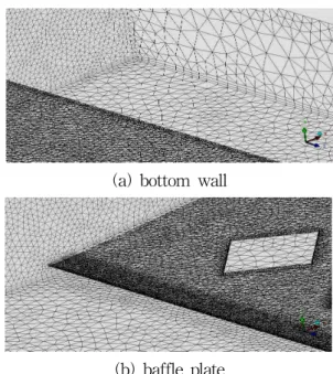
cm, W = 19.8 cm, and H = 4 cm). Fig. 1 shows the grid system in the rectangular channel.
Unstructured tetrahedral grids with prism smoothing are used in the vicinity of the bottom wall and the baffle surface to resolve high velocity gradients. The total number of nodes in those domains are more than 500,000 and total number of tetrahedrons is more than 1,500,000.
(a) bottom wall
(b) baffle plate
Fig. 1 Grid system arrangements around bottom wall and baffle plate
In the present numerical model, a uniform heat flux is specified on the bottom wall (heated wall), which defined at the same value with the experimental conditions. The channel inlet and outlet were set at the bulk velocity corresponding to Reynolds numbers. All walls in the rectangular channel except the bottom wall are defined as the adiabatic smooth walls.
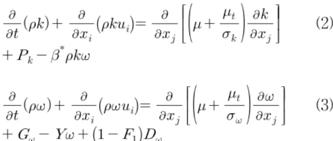
The zonal modelling uses Wilcox's model near solid walls and Launder and Sharma's model near boundary layer edges and in free shear layers, respectively. This switching is achieved with a blending function F1 of the model coefficients as follows:
SST model = F1⋅( - model)
+ (1-F1)⋅( - ε model) (1) where the standard was first proposed by
Wilcox10) as follows:
(2)
(3)
And - ε model was used by Launder and Sharma's model11).
The SST model requires the distance of a node to the nearest wall for performing the blending between and . The wall scale equation is the equation solved to get the wall distance, simply:
∇ (4)
where is the value of the wall scale. the wall distance can be calculated from the wall scale through:
wall distance ∇ ∇ (5)
3. Experimental facility
Pressure drop measuring device
Pressure drop measuring device
Power supply &
thermocouple readout
Foil heater with thermocouple Baffle
Fully developed flow To suction blower
Plexiglass
Wood
Fig. 2 Schematics of test apparatus
Fig. 2 shows a schematic diagram of the test apparatus. A suction-mode blower is used to draw air at room temperature through flow straighteners, passing through a long unheated straight rectangular channel with a cross-section of 19.8 cm x 4 cm and a length of 171.8 cm, finally through the heated test section with L = 71.2 cm. The channel has an aspect ratio of 4.95, and hydraulic diameter of Dh = 6.66 cm. The entrance section is long enough to ensure a
hydrodynamically fully developed flow just before the heated test channel. The left, right and upper sides of the channel are made of 5-mm-thick plexiglass plates, and the bottom side is made of 5-cm-thick wood plate. A total of twenty three so-flux stainless steel foil heaters of the size of 198 mm(L) x 30 mm(W) x 0.1 mm(T) are mounted on the bottom surface of the test section. These foil heaters are aligned perpendicular to the flow direction.
Twenty three copper constantan thermocouples are laid along the heated test section centerline and glued at each strip of the foil heater to measure the wall temperatures. Moreover, one thermocouple is placed at the inlet (10 cm upstream of the heated test section) and ten others are positioned at the outlet (9.2 cm downstream of the heated test section) to measure the inlet and outlet bulk air temperatures, respectively.
Baffle
Heater
5
0
m H
Insulator
n
5
0
c n
Fig. 3 Position of baffles in the test section
Photo. 1 Test section
Details of the baffle position in the test section are shown in Fig. 3. All baffle types mounted on the heated wall have a constant inclination angle of five degree. A gap (n) of 4 mm between heated surface and the baffle is maintained to
avoid flow stagnation. In all configurations, the first baffle and second baffles are placed at the positions (m) of 9.5 cm and (c) of 41 cm downstream from the start of the heated test section. Leading edge of the baffle is kept sharp to reduce possible flow disturbance by the protruding edge. In this study, the baffle made up of plexiglass has the size of length, 23.2 cm, width, 19.8 cm, and thickness, 5 mm. The view of test section used in this study is shown in Photo.
1. The square diamond holes of width, 2.55 cm, transverse gap, 1.2 cm, and longitudinal gap, 7.6 cm were manufactured. All of the thermocouples used in the experiment are carefully calibrated to an accuracy of 0.5oC. The experimental uncertainties are estimated using the procedure outlined by Kline and McClintock9). The variables measured in this experiment are wall temperature, air temperature, velocity and pressure drop. It is found that the uncertainties for Reynolds number, friction factor and Nusselt number are about 2.5%, 10.0%, and 7.8%, respectively.
4. Data Reduction
The local heat transfer coefficient (h) is calculated from the net heat transfer rate per unit surface area exposed to the cooling air, the local wall temperature (Tw), and the local bulk mean air temperature (Tb) as follows :
(6) where A is the total heat transfer area of the heated wall. The heat transfer rate ( ) is defined as:
(7) where Tb1 and Tb2 represent the fluid bulk temperatures at the entrance and exit, respectively. The local Nusselt number (Nu) is defined using the local heat transfer coefficient and the hydraulic diameter Dh for the rectangular channel:
(8) The Reynolds number is calculated on the basis of channel average velocity and channel hydraulic diameter. The channel average velocity is obtained from the flow rate of the circular tube at downstream of test section.
5. Results and discussion
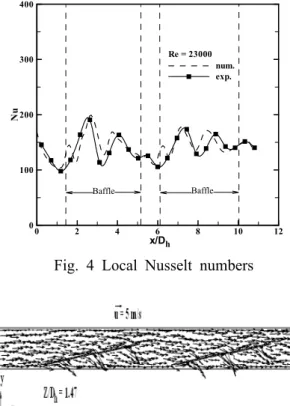
To verify validation of the predicted results, the test computations for the rectangular channel with 9-holed baffles were performed on the node number of 612,268 at the Reynolds number of 23,000 in Fig. 4.
x/D
Nu
0 2 4 6 8 10 12
0 100 200 300 400
num.
exp.
Baffle Baffle
h Re = 23000
Fig. 4 Local Nusselt numbers
Fig. 5 Flow field (x - y surface, z/Dh = 1.47) around the baffle at Re = 23,000
The present experimental data do not precisely match the numerical results. It is not surprising because the discrepancies between calculated and measured results may be attributed to variable fluid properties and the possible influence of buoyancy in the experimental system. In addition, as mentioned earlier, one thermocouple in each
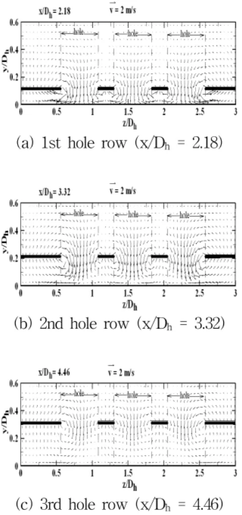
(a) 1st hole row (x/Dh = 2.18)
(b) 2nd hole row (x/Dh = 3.32)
(c) 3rd hole row (x/Dh = 4.46)
Fig. 6 Fluid flow pattern on the cutting-plane at y-z surface of the 1st baffle at Re = 23,000
heater gives the local wall temperature at channel centerline (location of jet impingement) and, therefore, presented results do not reflect span-averaged Nusselt number characteristics.
This figure shows that three peaks of the local
occur on each of baffle. It is due to the multiple impingement effect. This figure also shows that the peaks decline along the dimensionless location x/Dh. This is due to a divergent orientation of the baffle plate. This trend is more conspicuous in the 1st baffle because the axial velocity intensity is greater in the 1st baffle.
Fig. 5 depicts the flow field in the 9-holed baffle. This figure also shows that three rows of impinging jets occur on each baffle; i. e., first impingement is produced by the three holes at the first row of holes at the dimensionless axial location of x/Dh = 2.18, the second impingement
is produced by the second row of holes at x/Dh
= 3.32, and also the third impinging is produced by the third row of holes at the dimensionless axial location of x/Dh = 4.46 downstream from the start of the heater. The three rows of impingement jets also occur on the 2nd baffle.
(a) 1st hole row (x/Dh = 6.76)
(b) 2nd hole row (x/Dh = 7.9)
(c) 3rd hole row (x/Dh = 9.04)
Fig. 7 Fluid flow pattern on the cutting-plane at y-z surface of the 2nd baffle at Re = 23,000
Figs. 6 and 7 show fluid flow patterns on the cutting-plane of y-z coordinate at the 1st hole row, 2nd hole row, and 3rd hole row of two baffles at the bulk velocity of 2 m/s. The velocity intensities around the holes at the 1st hole row are much greater than 3rd hole row.
It be attributed to the fact that the space backward between the baffles and the bottom is more cramped at the 1st row and diverged along the baffle length. These figures depict more clearly that the inclination between the hole and the impact surface affects the transport
(a) 1st hole row (x/Dh = 2.18)
(b) hole row (x/Dh = 3.32)
(c) 3rd hole row (x/Dh = 4.46
Fig. 8 Isotherms on the cutting-plane at y-z surface of the 1st baffle at Re = 23,000
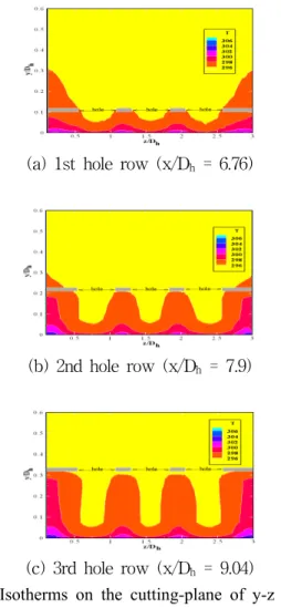
characteristics in the vicinity of the impact surface. Fig. 8 shows the isotherms at three cutting plane of the first, second and third row of holes of the 1st baffle (x/Dh = 2.18, 3.32, and 4.46) in the rectangular channel with 9-holed baffle. The structure of the temperature field is a reflection of the flow pattern. Fig. 9 shows the temperature contours at the cutting planes of the 2nd baffle. It is found that the temperature contour behaviours at these regions are not similar with the contours at the cutting planes of hole row in the 1st baffle. The difference is that those regions at the 2nd baffle are more dominated with hot fluid compared with the 1st baffle (Fig. 8) because the fluid-mixing toward the heated bottom surface by the holes of 1st baffle increases the air temperature downstream of the 1st baffle.
(a) 1st hole row (x/Dh = 6.76)
(b) 2nd hole row (x/Dh = 7.9)
(c) 3rd hole row (x/Dh = 9.04)
Fig. 9 Isotherms on the cutting-plane of y-z surface of 2nd baffle at Re = 23,000.
6. Conclusions
The numerical analysis predicted turbulent flow characteristics and heat transfer in a rectangular channel with two inclined baffles with 9 diamond type holes. The results are presented for a fixed inclination angle of 5o on each baffle (1st and 2nd baffles). Listed below are major findings:
1) The numerical predictions of flow and thermal characteristics depict that the structure of the temperature field is a reflection of the flow pattern.
2) The thermal contours at the 1st baffle are not similar with those at the cutting plane of hole row in the 2nd baffle.
3) The local Nusselt number is greatest around x/Dh=2.5.
4) The velocity intensities around the holes at the 1st hole row are much greater than 3rd hole row.
References
1. C. Berner, F. Durst and D. M. McEligot, 1984, "Flow around Baffles", ASME J. Heat Transfer, Vol. 106, pp. 743 -749.
2. Z. D. Chen and J. J. Chen, 1998, "Local Heat Transfer for Oscillatory Flow in the Presence of a Single Baffle within a Channel", Chemical Engineering Science, Vol. 53, No. 17, pp.
3177-3180.
3. M. A. Habib, A. M. Mobarak, M. A. Sallak, E. A. Abdel Hadi and R. I. Affify, 1994,
"Experimental Investigation of Heat Transfer and Flow over Baffles of Different Heights", ASME J. Heat Transfer, Vol. 116, No. 2, pp.
363-368.
4. O. N. Sara, T. Pekdemir, S. Yapici and M.
Yilmaz, 2001, "Heat Transfer Enhancement in a Channel Flow with Perforated Rectangular Blocks", Int. J. Heat Fluid Flow, Vol. 22, No.
5, pp. 509-518.
5. P. Dutta and S. Dutta, 1998, "Effect of Baffle Size, Perforation and Orientation on Internal Heat Transfer Enhancement", Int. J. Heat Mass Transfer, Vol. 41, No. 19, pp. 3005-3013.
6. P. Dutta and A. Hossain, 2005, "Internal Cooling Augmentation in Rectangular Channel using Two Inclined Baffles", Int. J. Heat Fluid Flow, Vol. 26, pp. 223-232.
7. M. Yilmaz, 2003, "The Effect of Inlet Flow Baffles on Heat Transfer", Int. Comm. Heat Mass Transfer, Vol. 30, No. 8, pp. 1169-1178.
8. Y. T. Yang and C. Z. Hwang, 2003,
"Calculation of Turbulent Flow and Heat Transfer in a Porous-baffled Channel", Int. J.
Heat Mass Transfer, Vol. 46, pp. 771-780.
9. S. J. Kline and F. A. McClintock, 1953,
"Describing Uncertainty in Single Sample Experiments", Mechanical Engineering, Vol.
75, pp. 3-8.
10. D. C. Wilcox, 2004, "Turbulence Modelling for CFD", DCW Industries, 2000-314.
11. B. E. Launder and B. I. Sharma, 1974,
"Application of the Energy-dissipation Model
of Turbulence to the Calculation of Flow near a Spinning Disc", Letters in Heat and Mass Transfer, Vol. 1, pp.131-138.