고체산화물 연료전지 금속연결재용 STS 444의 코발트 보호막 산화 특성
홍종은* , **, 임탁형*, 이승복*, 유영성***, 송락현* † , 신동열*, 이덕열**
*한국에너지기술연구원 신재생에너지연구부, **고려대학교 신소재공학과, ***한국전력연구원 전략기술연구소
Oxidation Properties of Cobalt Protective Coatings on STS 444 of Metallic Interconnects for Solid Oxide Fuel Cells
JONGEUN HONG* , **, TAKHYUNG LIM*, SEUNGBOK LEE*, YOUNGSUNG YOO***, RAKHYUN SONG* † , DONGRYUL SHIN*, DOKYOL LEE**
*Fuel Cell Research Center, New and Renewable Energy Research Division, Korea Institute of Energy Research, 71-2, Jang-dong, Yuseong-gu, Daejeon, Korea
**Department of Materials Science and Engineering, Korea Univ., 5-1 Anam-dong, Seongbuk-gu, Seoul, Korea
***Strategic Technology Laboratory, Korea Electric Power Research Institute, Korea Electric Power Corporation, Daejon, Korea
ABSTRACT
코발트 보호막 코팅이 적용된 페라이트계 스테인리스 스틸인 STS 430과 STS 444 소재에 대해 고체산화물 연료전지용 금속연결재로서의 고온 산화 특성에 대해 살펴보았다. 코발트 코팅층은 800℃
고온 산화 후 코발트 산화물 및 Co 2 CrO 4 , CoCr 2 O 4 , CoCrFeO 4 등과 같은 코발트가 함유된 스피넬 상을 형성하였다. 또한 페라이트계 스테인리스 스틸과 코발트 코팅의 계면에서 크롬과 철이 함유된 치밀 한 산화층을 형성하여 금속연결재 표면의 스케일 성장속도를 감소시키고 금속연결재 내에 함유된 크 롬의 외부 확산을 효과적으로 억제하였다. 한편 STS 430은 고온 산화 후 표면에 형성된 스케일 하부 에 SiO 2 와 같은 내부 산화물이 형성된 반면 STS 444는 표면 스케일 이외에 다른 내부 산화물은 확인 되지 않았으며 고온에서의 면저항 측정 결과, 코발트가 코팅된 STS 444의 전기 전도성이 STS 430 보 다 우수한 것으로 나타났다.
KEY WORDS : Solid oxide fuel cell(고체산화물 연료전지), Metallic interconnect(금속연결재), Ferritic stainless steel(페라이트 스테인리스 스틸), Protective layer(보호막), Cobalt coating(코발트 코팅), Electroplating(전기도금)
† Corresponding author : [email protected]
[ 접수일 : 2009.10.6 수정일 : 2009.11.26 게재확정일 : 2009.12.15 ]
1. Introduction
Fuel cells directly convert the chemical energy
of fossil fuels into electrical energy without com-
bustion or any mechanical process. Among the various types of fuel cells, solid oxide fuel cell (SOFC) is a high-energy power generation system operating at an elevated temperature higher than 1000℃ 1) . Interconnects are an important component of SOFC stacks. They separate fuel and oxidant gases and also electrically connect the anodes and the cathodes of the adjacent fuel cells in stacks.
Therefore, SOFC interconnects must have a high temperature oxidation resistance in both oxidizing and reducing atmospheres and a high electrical conductivity. Ceramic and metallic materials are used as interconnects for SOFC applications 2) . Since the decrease of the operating temperature of SOFCs enables metallic interconnects to replace ceramic interconnects, many studies have been recently focused on discovering appropriate materials for metallic interconnects, due to advantages such as high electrical and thermal conductivities, low material cost, easy fabrication, and mechanical strength.
Fe-Cr alloys of ferritic stainless steel containing chromium content higher than 16 wt. % are especially considered as promising materials. They represent a similar thermal expansion coefficient (TEC) of 12 × 10 -6 compared to that of yttria- stabilized zirconia (YSZ), electrolyte materials 3) . However, the high temperature oxidation is one of the crucial problems in ferritic stainless steels due to the formation of an oxide scale of chromia (Cr 2 O 3 ). The scale increases the resistance of the system so that it deteriorates the performance and long term stability of the SOFC stacks. In addition, the chromium poisoning occurred by the chromium diffusion from the oxide scale into the YSZ electrolyte in the cathode side also decreases the power density of the system 1,4,5) .
In order to reduce the difficulties, various surface coatings have been investigated, which are electri- cally conductive, relatively compact, and chemi-
cally compatible and also prevent the migration of chromium into the cathodes.
Perovskites of (La, Sr)MnO 3 6,7)
and spinels of (Mn, Cr) 3 O 4 8) or (Mn, Co) 3 O 4 9) are reported to be pro- mising materials for the protective coating of metallic interconnects. The protective coatings are effective to decrease oxidation kinetics and improve electrical properties of SOFC metallic interconnects at high temperatures. It is also noted that a (Mn 1.5 Co 1.5 )O 4
spinel layer is successful to suppress chromium outward diffusion 8) . In addition to perovskites and spinels, some studies based on a metallic coating of a transition element selected from Co, Mn, Ni, Cu and Fe have been reported. Badwal et al. 10) reported oxide coatings including at least one metal, M, of the transition elements. A M-Cr spinel layer was created between the metallic substrate containing chromium and the coating layer, resul- ting in a reaction between the coating layer and the surface oxide scale formed on the substrate.
Stanislowski et al. 11) reported that metallic coatings of Co, Ni, and Cu and their oxides effectively inhibited the growth rate of the scale. Also, chro- mium migration could be suppressed by more than 99%. Zahid et al. 12) fabricated MnCo 2 O 4 layers with Co 3 O 4 coating by a wet powder spraying on the surface of Crofer22 APU. After 1000 h of oxidation, a scale formed at the interface between MnCo 2 O 4 layer and MnCr 2 O 4 sub-layer on Crofer22 APU was stable. Liang et al. 13) examined electrical and thermal properties of various spinel oxides.
They observed that cobalt containing spinels repre-
sented higher electrical conductivities than that of
Cr 2 O 3 . In our previous study, STS 430 with a
protective cobalt coating was examined as a metallic
interconnect for SOFCs. It indicated an improved
conductivity and chromium retention at a high
temperature but it was obviously seen that an
internal oxide of SiO 2 was formed below the surface
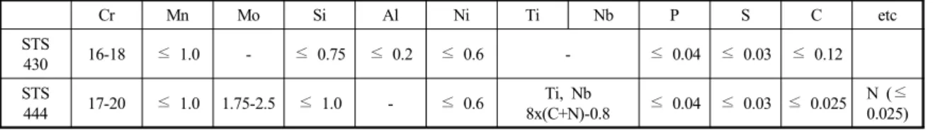
Table 1 Typical chemical composition (wt. %) of STS 430 and STS 444
Cr Mn Mo Si Al Ni Ti Nb P S C etc
STS
430 16-18 ≤ 1.0 - ≤ 0.75 ≤ 0.2 ≤ 0.6 - ≤ 0.04 ≤ 0.03 ≤ 0.12
STS
444 17-20 ≤ 1.0 1.75-2.5 ≤ 1.0 - ≤ 0.6 Ti, Nb
8x(C+N)-0.8 ≤ 0.04 ≤ 0.03 ≤ 0.025 N (≤
0.025)
of STS 430 after oxidation in both the coated and uncoated STS 430. In addition, the surface scale of the uncoated STS 430 was peeled off after oxidation, which was induced by SiO 2 with a smaller thermal expansion coefficient compared to that of steel 14) . Therefore, it would affect not only the stability but also the electrical performance of SOFC stacks since SiO 2 being an insulating material, has a low conductivity. In this study, we intend to improve the electrical conductivity and to enhance the oxidation resistance by means of a protective coating on a ferritic stainless steel as the metallic interconnect for SOFCs. Therefore, we evaluate the oxidation property of STS 444 coated with cobalt. The protective cobalt coating is prepared by electroplating on STS 444 subsequently the electrical conductivity and oxidation properties are investigated in comparison to STS 430 at 800℃
in air.
2. Experimental
2.1 Preparation of protective coating Commercial ferritic stainless steels, STS 430 and 444, are used as metallic interconnect materials for SOFC applications. The typical composition of the steels are listed in Table 1. STS 444 contains a higher chromium concentration than that of STS 430. Samples of STS 430 and 444 have an area of 10 × 10 mm 2 and 3 mm and 1 mm thickness, respectively. Each coupon is mechanically polished with SiC paper to # 2000 grit. For degreasing,
each piece is ultrasonically cleaned in 0.1 M sodium hydroxide (NaOH) solution and then in acetone, respectively and subsequently rinsed in distilled water. The cobalt coating layer is prepared by electroplating. Each sample is pickled in 10%
hydrochloric acid (HCl) for 1 min to remove the surface oxide scale on the stainless steel just before electroplating, followed by rinsing in distilled water.
A cobalt plate with dimensions of 15 × 15 × 1 mm and the coupon of the stainless steel are used as anode and cathode in electroplating, respectively.
An electroplating solution is prepared by dissolving 1 M of CoSO 4 ・7H 2 O, 0.3 M of CoCl 2 ・6H 2 O, and 0.2 M of H 3 BO 3 in 0.5 L of distilled water which was degassed by blowing N 2 gas for 6 h 15) . Cobalt is electroplated on the coupons at a current density of 50 mAcm -2 using Digital Sourcemeter 2400 series (KIETHLEY) for 40〜70 min in the solution, resulting in a coating of ca. 25〜65 ㎛ thickness.
After electroplating, each specimen is rinsed with distilled water (heated to 70〜80℃) and ethanol, respectively, followed by drying at 200℃ in air.
The coated substrate is heat-treated at 800℃ for 10 h in a reducing atmosphere (10% H 2 and N 2
gas) to reinforce the adhesion between cobalt coating layer and stainless steel before the high temperature oxidation.
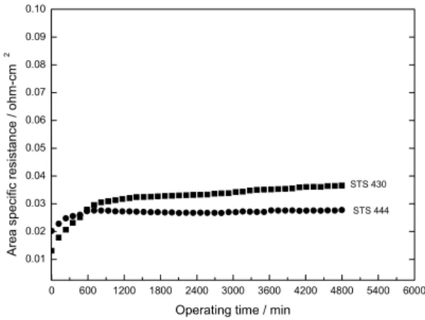
2.2 ASR measurement
The area specific resistance (ASR) is measured
for 800 h at 800℃ in air to evaluate electrical
conductivities of cobalt coated and uncoated steels.
Fig. 1 XRD results of cobalt coatings on SUS 444; (a) as- deposited and (b) 1 h, and (c) 320 h oxidation at 800 ℃ in air.
Fig. 2 Surface images of (a) uncoated and (b) cobalt coated US 444 after oxidation at 800 ℃ in air for 320 h.
The ASR test is conducted by a four-probe method.
Platinum mesh and platinum wires are used for contact media and current leads, respectively. A dead load of 4 × 10 4 Pa is applied on the platinum mesh during the ASR test. Each platinum mesh has two welded platinum leads. A constant current density of 500 mAcm -2 is supplied by Digital Sour- cemeter 2400 series (KIETHLEY) while the voltage is measured.
2.3 Chemical characterizations
Electroplated samples are characterized by X-ray diffraction (XRD) to confirm phase transformations of cobalt coatings along with the oxidation time at 800℃. Scanning electron microscopy (SEM) and energy dispersive spectroscopy (EDS) are used to identify the cross-section, surface morphology, and elemental distributions of the cobalt coatings and interconnects.
3. Results and discussion
3.1 X-ray diffraction analysis
Cobalt coatings are characterized by XRD for
the samples of as-deposited and after oxidation for 1 h and 320 h, respectively, at 800℃ in air (Fig. 1). The as-deposited cobalt coating on STS 444 exhibits a pure cobalt phase with hexagonal structure (Fig. 1(a)). The cobalt coating is oxidized to CoO and CoCo 2 O 4 after oxidation for 1 h. It can be seen that CoCo 2 O 4 of cobalt oxide is confirmed after oxidation for 320 h indicating a complete oxidation of the cobalt coating. In addition, a few cobalt containing spinel phases are developed such as Co 2 CrO 4 , CoCr 2 O 4 , and CoCrFeO 4 after 320 h at 800℃ in air (Fig. 1(c)). Thus, cobalt coating layers are transformed into cobalt oxide and cobalt con- taining spinel phases after the long-term oxidation.
3.2 Microstructure and phase analysis The surface morphology and cross-section of cobalt coatings on STS 444 are investigated by scanning electron microscopy after oxidation in air.
The cobalt-coated steel is heat-treated in 10% H 2
and N 2 gas in order to enhance the adherence between STS 444 and the cobalt coating prepared by electroplating before oxidation.
Fig. 2 shows surface images of uncoated and the cobalt-coated STS 444 after oxidation at 800℃
for 320 h. The surface morphology of the uncoated
steel is coarse and porous with agglomerated
particles. On the other hand, cobalt coated STS
444 reveals a uniform and smooth morphology
compared to that of the uncoated stainless steel.
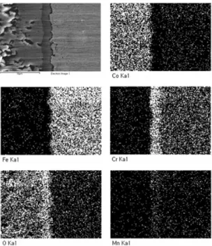
Fig. 3 Elemental mappings of the cross-section of cobalt coated SUS 444 after oxidation at 800 ℃ in air for 1020 h.
Fig. 4 The EDS line scan of the cross-section of cobalt coated STS 444 after oxidation for 1020 h.
Also, the cobalt coated surface indicates a dense surface with good adherence.
The SEM micrograph and elemental mapping of the cross-section of cobalt coated STS 444 after 1020 h are shown in Fig. 3. It can be seen that a dense layer of chromium oxide is thermally grown at the interface between STS 444 and the cobalt coating layer. The result of elemental mapping reveals no diffusion of chromium proceeded into the coating layer after the long-term oxidation in air.
Also, the result of EDS line scan indicates that a dense oxide scale containing Co, Fe, Cr-, and a small amount of Mn is formed at the interface between STS 444 and the cobalt coating as shown in Fig. 4. The oxide scale consists of cobalt con- taining spinel phases such as Co 2 CrO 4 , CoCr 2 O 4 , and CoCrFeO 4 which are confirmed by XRD analysis in Fig. 1. In addition, a small amount of Mn is detected in the dense scale as shown in Fig. 3 and
4. It is normally reported that a small amount of Mn contained in the ferritic stainless steel is trans- formed into (MnCr) 3 O 4 oxide on top of the scale grown on the surface of the steel after high tem- perature oxidation. The (MnC)r 3 O 4 oxide is also electrically conductive and reduces the oxidation rate of chromium containing stainless steels 16) . It can be obviously seen that chromium element rarely exists in the cobalt coating after oxidation for 1020 h due to the cobalt containing dense scale as shown in Fig. 4. A possible explanation for the chromium retention is that transition metals like Co, Ni, and Cu and their oxides are known to not only effectively reduce the growth rate of the scale but also prevent the chromium outward diffusion 11) . Thus, the chromium diffusion is effectively inhibited by the cobalt oxide layer, followed by the for- mation of a dense oxide scale thermally grown at the interface after high temperature oxidation.
The uncoated STS 444 has no spallation from the surface oxide after oxidation as shown in Fig.
2(a). In our previous work, an oxide scale developed
on uncoated STS 430 was partially peeled off after
long-term oxidation since the subscale of SiO 2
Fig. 5 SEM images of cross-sections of (a) uncoated STS 430
14)and (b) uncoated STS 444 of Fig. 2 (a) after oxidation.
Fig. 6 EDS analysis of the surface of uncoated STS 444 as shown in Fig. 2 (a).
0 600 1200 1800 2400 3000 3600 4200 4800 5400 6000 0.01
0.02 0.03 0.04 0.05 0.06 0.07 0.08 0.09 0.10
STS 430 STS 444