http://dx.doi.org/10.5916/jkosme.2015.39.5.522 Original Paper
This is an Open Access article distributed under the terms of the Creative Commons Attribution Non-Commercial License (http://creativecommons.org/licenses/by-nc/3.0), which permits unrestricted non-commercial use, distribution, and reproduction in any medium, provided the original work is properly cited.
Copyright ⓒ The Korean Society of Marine Engineering
†Corresponding Author (ORCID: http://orcid.org/0000-0002-3091-9494): Department of Naval Architecture and Ocean Engineering,, Koje College, 91 Majen 1 gil, Geoje, Gyeongsangnamdo, Korea, E-mail: [email protected], Tel: 055-680-1579
1 Maritime R&D center LIG Nex1 Co., Ltd., E-mail: [email protected], Tel: 031-8026-4414
A Study on Attitude Heading Reference System Based Micro Machined Electro Mechanical System for Small Military Unmanned Underwater Vehicle
A-Rom Hwang†․ Seon-Il Yoon1
(Received November 25, 2014; Revised January 12, 2015;Accepted June 13, 2015)
Abstract: Generally, underwater unmanned vehicle have adopted an inertial navigation system (INS), dead reckoning (DR), acoustic navigation and geophysical navigation techniques as the navigation method because GPS does not work in deep under- water environment. Even if the tactical inertial sensor can provide very detail measurement during long operation time, it is not suitable to use the tactical inertial sensor for small size and low cost UUV because the tactical inertial sensor is expensive and large. One alternative to INS is attitude heading reference system (AHRS) with the micro-machined electro mechanical system (MEMS) inertial sensor because of MEMS inertial sensor's small size and low power requirement. A cost effective and small size attitude heading reference system (AHRS) which incorporates measurements from 3-axis micro-machined electro mechanical system (MEMS) gyroscopes, accelerometers, and 3-axis magnetometers has been developed to provide a complete attitude sol- ution for UUV. The AHRS based MEMS overcome many problems that have inhibited the adoption of inertial system for small UUV such as cost, size and power consumption. Several evaluation experiments were carried out for the validation of the developed AHRS's function and these experiments results are presented. Experiments results prove the fact that the devel- oped MEMS AHRS satisfied the required specification.
Keywords: Unmanned underwater vehicle, Attitude heading reference system, Micro-machined electro mechanical system, Evaluations experiment
1. Introduction
Unmanned underwater vehicles (UUV) have become a main tool for underwater survey operation in scientific, military, and commercial applications; the usage of these vehicles has also extended to the inspection of ship hulls [1] and underwater man-made structures [2][3] because of the ability of autono- mous navigation. The usage of UUV in military area has also been increasing and some small UUV of which length is be- low 2 m especially is used in the some hazardous mission as like mine countermeasure (MCM) [4]. The navigation system is most important system for UUV because the correct posi- tion information is essential to military mission and commer- cial mission. Since GPS-signal is not accessible underwater, the inertial navigation system (INS) and acoustic navigation system have usually been used as the navigation system of UUV. Even if the tactical inertial sensor has been generally used in INS of UUV for confidential mission, it is hard to in- stall INS to small UUV in view of the cost and power con- sumption[5]. One alternative to INS is attitude heading refer-
ence system (AHRS) with the micro-machined electro mechan- ical system (MEMS) inertial sensor because of MEMS inertial sensor's small size and low power requirement. Since AHRS also integrate the results of accelerometer and gyro for the at- titude calculation, it is necessary to use the auxiliary sensor for measuring the absolute direction of vehicle for preventing the accumulation of error through integration. In this paper, the AHRS with MEMS accelerometer, gyro and magnetometer which is developed for small military UUV is introduced and the evaluation process and results are presented.
2. Attitude heading reference system for small UUV
2.1 Configuration
We has been developed small UUV for some military mis- sion as like the submarine training. The AHRS based MEMS had been also developed for the developed small military UUV. The AHRS is designed to be equipped with the 3 axis
MEMS gyro, 3 axis MEMS accelerometer and 3 axis MEMS magnetometer. Figure 1 presents the overview of the AHRS and the specifications of AHRS are summarized at Table 1.
The navigation computer in AHRS calculates the acceleration in 3 axis, roll, pitch and yaw with sensor's output with calcu- lation algorithm based Kalman filter. The configuration of AHRS is presented at Figure 2.
Figure 1: AHRS based MEMS for small high speed UUV.
Figure 2: Configurations of AHRS based MEMS
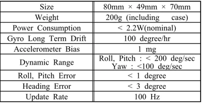
Size 80mm × 49mm × 70mm
Weight 200g (including case) Power Consumption < 2.2W(nominal) Gyro Long Term Drift 100 degree/hr
Accelerometer Bias 1 mg
Dynamic Range Roll, Pitch : < 200 deg/sec Yaw : <100 deg/sec Roll, Pitch Error < 1 degree
Heading Error < 3 degree
Update Rate 100 Hz
Table 1: Specification of AHRS based MEMS
2.2 Attitude determination
Even if strapdown Inertial Navigation Systems (INS) can pro- vide attitude and heading estimates after initialization and align- ment by integrating the attitude rates that are related to attitude angles and the angle rate measurement of the gyroscopes, the strapdown INS implementation suffers from error growth due to the integration of the inertial gyro measurements that contain various errors. Therefore MEMS AHRS can not implement
the integration method due to its high error growth rate.
Alternative for AHRS based MEMS sensor is the method using transform matrix from linear acceleration to specific force based on the Euler’s theorem called the a direction co- sine matrix(DCM) method. According to Euler’s theorem, we can specify the orientation of the body frame relative to the navigation frame using three angles known as Euler angles which can be obtained using three successive rotations about different axes, known as the Euler angle sequence[6][7].
Roll and pitch angle are calculated with DCM under the as- sumption that UUV dose not move and the gravity is
. Each specific force is described as Equation (1)
, (1)is the measured specific force at body fixed coordinate and is the measured specific force navigation coordinate.
Transformation matrix from body coordinate to navigation co- ordinate is in Equation (2)
(2)
where is ∙ sin ∙∙ cos∙
The relationship between and is described as follows
sin
sin cos
cos
. (3) From Equation (3), the pitch and roll are calculated as follows. tan
tan
. (4) If the alignment time is
, pitch and roll in Equation (4) are calculated through integration as like Equation (5). tan
tan
. (5)Journal of the Korean Society of Marine Engineering, Vol. 39, No. 5, 2015. 6 524 As shown Equation (2), the yaw angle can not be calculated
from transform matrix using linear accelerometer. Therefore another measurement other than linear acceleration is required and the angular acceleration is used to solve this problem in this paper because the developed AHRS contains 3 axis gyro.
The relationship between the rate of Euler’s angles and the output from gyro is describes as follows;
cos sin sin cos
cos sin sin cos
sin sin
cos cos
(6)
From Equation (6), the derivative equation can be derived as follow;
sin tan costan cos sin
sin sec cossec
(7)The yaw angle can be calculated from Equation (7) with the calculated roll, pitch angles from Equation (5). Since Equation (5) and (7) require to solve the integration and determination, the estimation method is essential to solve the attitude deter- mination problem. Therefor the extended Kalman filter (EKF) is used in this paper. The system state vector and measure- ment vector for EKF is summarized as follows. The state error vector has six components consisting of a 3-vector quaternion error and 3-vector gyro bias error. This AHRS has the G-slave mode which gives more gain of gyros to attitude calculation block than accelerometers in addition to general Kalman filter.
It reduces attitude errors due to the centrifugal force when the vehicle turns. The detail procedure and the value of parameter for EKF is omitted because those are classified as confidential.
Several evaluation experiments were carried out for the vali- dation of the developed AHRS's function. Experiments are classified as the static motion test, land mobile vehicle test, and the experiment with flight motion simulator (FMS).
Figure 3: Configurations of Navigation Filter
3. Evaluation Experiment 3.1 Magnetometer Calibration
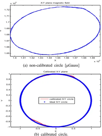
The magnetometer which measures the strength of earth magnetic field can produce the precise absolute yaw angle even if the price of magnetometer is low among the navi- gation senor. However, since the distortion of geomagnetic cause the error of the calculated yaw angle from the magneto- meter, the magnetometer must be calibrated to remove the ef- fect of environmental error for example soft iron effect and hard iron effect. The magnetometer is calibrated through the test with rate table which simulates the 3 degrees of freedom motion of UUV. The measured yaw angles from non cali- brated and calibrated magnetometer are depicted with Figure 4.
Figure 4 proved that the non calibrated magnetometer was dis- torted by environmental effect and magnetometer calculated the absolute direction after calibration.
1.6 1.61 1.62 1.63 1.64 1.65 1.66 1.67 1.68 1.69 x 10⁶ 1.65
1.66 1.67 1.68 1.69 1.7 1.71 1.72
x 106 X-Y plane magnetic field
X
Y
(a) non-calibrated circle [μGauss]
-1 -0.5 0 0.5 1
-1 -0.8 -0.6 -0.4 -0.2 0 0.2 0.4 0.6 0.8
1 Calibrated X-Y plane
X
Y calibrated X-Y circle
Ideal X-Y circle
(b) calibrated circle.
Figure 4: Calibration circle of 2 dimensional circle in x-y plane
3.2 Static test
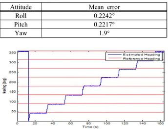
The static motion test was preformed to measure the output sig- nal of the AHRS when roll, pitch, and yaw of rate table were the fixed angle. The static motion test results are summarized at Table 2. Since the error of yaw result in table are very large comparing those of role and pitch, the detail result of yaw are describe at Figure 5. Figure 5 presents the fact that the developed AHRS can measure the stable yaw in all direction with small error.
Attitude Mean error
Roll 0.2242°
Pitch 0.2217°
Yaw 1.9°
Table 2: Error of AHRS based on MEMS under static motion test
Figure 5: Measured heading under station motion test.
3.3 Kinematic test
The field operating test on land was performed for the meas- uring the dynamic characteristic of AHRS's roll and pitch through repeated line movement. The measuring data was com- pared with the data from HG1700 which is the tactical inertial sensor and manufactured by Honeywell. Leveling error between the developed AHRS and HG1700 are presented at Figure 6.
The standard deviations of error in Figure 6 are 0.439° about roll and 0.726° about pitch. Figure 6 shows that the measuring function of our AHRS about roll and pitch has a good perform- ance even if the AHRS is designed based MEMS technology.
(a) Roll error
(b) Pitch error
Figure 6: Kinematic test result of roll and pitch.
3.4 Experiment with FMS
The experiment using FMS were carried out for the ver- ification of AHRS and real auto pilot control algorithm of
small UUV. The sequence and hardware interface of the ex- periment is presented in Figure 7. The conditions of the test are summarized at Table 3.
Figure 7: HILS interface block-diagram of UUV.
Table 3: Conditions for the experiments with FMS.
Condition I II
Target Depth 50 m 50 m
Target Heading 30° -30°
Operating Time 180 sec 180 sec
Velocity 16 knots 16 knots
The measuring data from the AHRS and flight motion simu- lator (FMS) during the test about 2 cases in Table 3 are shown at Figure 8. Figure 8 shows the fact that there are some difference between AHRS and FMS and the oscillation of AHRS data after the yaw of vehicle is reached.
Although there are erroneous and oscillating data from AHRS, the results in Figure 8 show that the error was below 3° and didn't diverge. Since the small error can be considered as the character- istic of MEMS and there was no accumulative error after reaching at certain yaw value, it is considered as to be proven that the de- veloped AHRS can be implemented into real small UUV.
(a) Target heading -30 deg.
(b) Target heading 30 deg.
Figure 8: HILS results under results at table 3.
Journal of the Korean Society of Marine Engineering, Vol. 39, No. 5, 2015. 6 526
4. Conclusion
This paper presents the new developed AHRS based MEMS suitable for small UUV of which length is 1.5m and width is 15 cm. The attitude determination algorithm was developed us- ing DCM method and EKF. The calibration and several tests that are static motion test, kinematic test and experiment with FMS were performed for the evaluation of the developed AHRS. The static motion test and mobile land vehicle test show that the developed AHRS can provide the accurate atti- tude information if the magnetometer in AHRS is calibrated properly. Although there are some errors in experiment results with FMS, it is proved that the developed AHRS can produce the attitude information which is not divergence.
References
[1] H. Kondo, T. Maki, T. Ura, and T. Sakamaki, “AUV navigation based on multi-sensor fusion for breakwater observation,” Proceedings of ISARC, pp. 72-77, 2006.
[2] D. Ribas, P. Ridao, J. D. Tardos, and J. Neira,
“Underwater SLAM in man-made structured environ- ments,” Journal of Field Robotics, vol. 25, no. 11, pp.
898-921, 2008.
[3] M. Walter, F. Hover, and J. Leonard, “SLAM for ship hull inspection using exactly sparse extended in- formation filters,” Proceedings of the IEEE International Conference on Robotics and Automation, pp. 1463-1470, 2008.
[4] C. von Alt, “REMUS 100 transportable mine counter- measure package,” Proceedings of the IEEE Oceans Conference, pp. 1925-1930, 2003.
[5] K. H. Yim, S. I. Yoon, and T. Y. Kim, “Kalman fil- ter with the intelligent algorithm for the underwater navigation system,” Proceedings of the Underwater Defense Technology Conference, 2002.
[6] D. H. Titterton and J. L. Weston, Strapdown inertial navigation technology, Peter Peregrinus Ltd. 1997.
[7] N. S. Reddy and J. Murray, “Transfer orbit stage gy- rocompass alignment algorithm twist and sway envi- ronmnet for mars observer mission on commercial ti- tan,” IEEE Aerospace and Electronic Systems Magazine, vol. 6, no. 2, pp. 3-7, 1991.