1. Introduction
The condenser is an essential facility in power plants and large-scale chemical plants. Its function is to condense the high temperature steam that operated the turbine to water, using seawater flowing through a water-box. Also, it enhances the efficiency of the power plant etc., by in- creasing the generating capacity, through reducing the ex- haust pressure of the turbine. Several tens of thousands of tubes are installed in the condenser, and seawater flows inside tubes [1]. The operating temperature of the shell side in the condenser of a nuclear power plant shows the range of 22.95~43.5 oC and the temperature range of flow- ing seawater inside the tube is from -2.4 to 28.7 oC. Since the condenser is in contact with high temperature’s steam and low temperature’s seawater, if pollution of the secon- dary system by leakage of the condenser tube occurs, the working lifespan of the steam generator, which is one of
the important facilities of a nuclear power plant, may be reduced. Therefore, suitable materials for condenser tub- ing should be selected with the general consideration of corrosion resistance, strength, modulus of elasticity, heat transfer, joint ability between tube sheet and tube by ex- panding or welding, and tube cleaning.
Because of excellent corrosion resistance in seawater, titanium has been used as one of the materials of tube and tube sheet for condensers in nuclear power plants [1].
However, the tube leakage and distortion by falling of sub- stance, erosion by high-pressure steam, or sand erosion in titanium tube at the upper side of the condenser can occur, and the tubes may be failed by hydrogen embrittlement.
For example, tube leakage accidents have occurred by dump steam in the condenser, or falling of substance onto internal structure. Whenever any damages in condenser tubes occurs, Eddy Current Testing (ECT) is conducted, and on the basis of test results, the damaged tubes are plugged. In order to improve the above situation, many designers of the power plants have reviewed a plan to
The Effect of Shielding N
2gas on The Pitting Corrosion of Seal-welded Super Austenitic Stainless Steel
by Autogenous Welding
Ki Tae Kim1, Hyun Young Chang2, and Young Sik Kim1,†
1Materials Research Center for Clean and Energy Technology, School of Materials Science and Engineering, Andong National University, 1375 Gyeongdongro, Andong, Gyeongbuk, 36729, Korea
2Power Engineering Research Institute, KEPCO Engineering & Construction Company, 269 Hyeoksinro, Gimcheon, Gyeongbuk, 39660, Korea
(Received December 21, 2016; Revised March 03, 2017; Accepted March 07, 2017)
Many research efforts on the effect of nitrogen on the corrosion resistance of stainless steels have been reported, but little research has been conducted on the effect of nitrogen for the weldment of stainless steels by the seal-weld method. Therefore, this work focused on the determining the corrosion resistance of tube/tube sheet mock-up specimen for sea water condensers, and elucidating the effect of shielding nitrogen gas on its resistance. The pitting corrosion of autogenously welded specimen propagated preferentially along the dendritic structure. Regardless of the percent of shielding nitrogen gas, the analyzed nitrogen contents were very much lower than that of the bulk specimen. This can be arisen because the nitrogen in shielding gas may partly dissolve into the weldment, but simultaneously during the welding process, nitrogen in the alloy may escape into the atmosphere. However, the pitting resistance equivalent number (PREN) of the interdendrite area was higher than that of the dendrite arm, regardless of the shielding gas percent; and the PREN of the interdendrite area was higher than that of the base metal; the PREN of the dendrite arm was lower than that of the base metal because of the formation of (Cr, Mo) rich phases by welding.
Keywords: super austenitic stainless steel, autogenous GTAW, seal-weld, shielding nitrogen gas, pitting corrosion, critical pitting temperature
†Corresponding author: [email protected]
substitute titanium tubes in the upper side with super stain- less steel tubes having relatively excellent properties for steam and sand erosion, tensile strength, elongation, hard- ness, elastic coefficient etc. Recently in Korea, super aus- tenitic stainless steel tubes for 30% of the tube of the upper side’s tubes of the condenser have been applied to reduce the steam erosion [1].
The applied super austenitic stainless steel contains 6%
Mo and high nitrogen content, and thus their additions generated a synergistic effect by the bipolar passive film [2]. The steel then revealed its superior corrosion resist- ance to pitting and crevice corrosion, and stress corrosion cracking, and has proven to be one of the suitable materi- als for seawater facilities.
However, because the welding between super stainless steel tubes and titanium tube sheet at the early stage of the application was impossible, the joint between them was sealed only by the mechanical expansion method.
Because carbon steel tube sheet was cladded by titanium, seal-welding between the cladded titanium tube sheet and super austenitic stainless steel tube couldn’t be performed, and carbon steel tube sheet was then corroded by the in- gress of seawater. Thus corrosion product from carbon steel tube sheet was observed on the surface of tube sheet through mechanically expanded crevices [3]. Therefore, tube sheet was fabricated by the two processes: the upper tube sheet was clad with super austenitic stainless steel, and the other was clad with titanium. After mechanical tube expanding, the crevice between tube and tube sheet was seal-welded.
A weld joint can be developed by just melting of the edges of plates, sheets or tubes to be welded, especially when the thickness is lesser than 5 mm thickness. A weld joint by melting the facing surfaces and subsequently sol- idification only without using any filler metal is termed an “autogenous weld” [4]. Thus, the composition of the autogenous weld metal corresponds to the base metal only.
When high nitrogen-bearing super austenitic stainless steel was welded by the Gas Tungsten Arc Welding (GTAW) method, desorption of nitrogen from the weldment could
occur, and thus the mechanical properties and corrosion resistance might be affected; and in particular, nitrogen in stainless steels is one of the beneficial elements to en- hance the passive properties. Heubner et al. and Rockel et al. have reported that the impact factor of nitrogen is 30 times the effect of chromium in the PREN [5,6]. They showed that the critical pitting temperature (CPT) in- creased linearly in proportional to PREN.
Suutala and Kurkela determined the CPTs of base metal and welded metal of austenitic stainless steels [7] and re- vealed that the CPT of welded metal was lowered than that of the base metal. Therefore, in order to maintain the corrosion resistance of welded metal, higher Mo-bear- ing filler metal than that of the base metal, or an insert ring for seal-welding between tube and tube sheet can be used. In the case of an insert ring, it was well known that the ring can offer better corrosion resistance than the base metal. However, the use of an insert ring is not effec- tive from an engineering aspect, because of the high num- ber of condenser tubes (of more than 20,000); and even if the insert ring is applied, the corrosion resistance of the weldment might be reduced, because of the difficulties of post weld heat treatment in the field. Therefore, another way to maintain corrosion resistance is the application of shielding gas including nitrogen gas. The addition of nitro- gen gas can compensate for the desorption of nitrogen from weldment more than that of 100% Ar shielding gas, and its corrosion resistance was a little improved [8].
However, if the shielding nitrogen gas exceeded any limit, the CPT was reduced, and the nitrogen content in weld- ment didn’t be increased further.
Many researches on the effect of nitrogen on the corro- sion resistance of stainless steels have been reported, but little research has been conducted on the effect of nitrogen for the weldment of stainless steels by the seal-weld method. Therefore, this work focused on determining the corrosion resistance of seal-welded tube/tube sheet mock-up specimen for sea water condensers, and elucidat- ing the effect of shielding nitrogen gas on its resistance.
Table 1 Chemical composition of tube sheet and tube for mock-up test
Material
Chemical compositions, wt%
PREN30
Cr Ni Mo Mn Si Cu N C P Fe
UNS S32050 23.52 22.01 6.24 0.28 0.09 0.08 0.32 0.016 0.023 bal. 52.1
*PREN30(Pitting Resistance Equivalent Number) = %Cr + 3.3(%Mo + 0.5%W)+ 30%N
2. Experimental Methods
2.1 Preparation of Mock-up specimen
Mock-up specimen for the corrosion test was prepared by GTAW according to KS D 0297(2009) [9]. The base metal for the tests was super austenitic stainless steel (SASS) and its PREN30 was 52.1. The thickness of the clad SASS’s tube sheet was 6 mm and the SASS tube thickness was 0.889 mm. Table 1 shows the chemical composition of the tube sheet and tube. The shielding welding gas was controlled as 100%Ar, 3%N2+97%Ar, 5%N2+95%Ar, and 8%N2+92%Ar. The peak welding cur- rent was 80A, and the welding voltage was 11.1~12.7V.
The travel speed was 135 mm/min, and thus the heat input was 0.395 ~ 0.452 kJ/mm. Fig. 1 shows one of the mock-up specimens.
2.2 CPT measurement
CPT measurement test was performed by A KS D 0297(2009) [9] and ASTM G48-03 A [10]. The mock-up specimen was polished using a SiC Paper #120 and then passivated for 24h in a desiccator. The test solution was 6% FeCl3. If the weight loss showed over 0.1 mg/cm2, the specimen was checked by liquid penetration test to detect the pit sites. The pit depth was measured by 3D digital video-microscopy (HIROX KOREA KH-7700) and the CPT means the minimum temperature of the test sol- ution for which the pit depth exceeds 0.025 mm 2.3 Throat thickness and hardness measurement ASME CODE 2004 Section VIII, Division 2, "Article
F-3 - “Special Requirements for Tube-To-Tube sheet Welds" requires the minimum throat thickness to be over 2/3 of the tube thickness [11]. The mock-up specimen was cut in 4 directions of 0°, 90°, 180°, and 270°. After the etching on cross-section by ASTM A262 etch test [12], the throat thickness was measured by a 3D digital vid- eo-microscopy (HIROX KOREA KH-7700). The Vickers hardness of the base metal and welded area was measured by Akashi, AVK-C100.
2.4 Microstructure and composition analysis
A thermodynamical phase diagram of the experimental alloy was plotted using Thermo-Calc®, and during the cooling after welding, some phases to be formed were forecasted. Microstructures of the weldment and corroded areas were obtained using a SEM-BSE mode (VEGA II LMU, TESCAN). The crystallographic microstructure was analyzed using an XRD (D/max RAPID-S, Rigaku) and its scan rates were 4°/min and 1°/min.
The composition of dendrite and interdendrite areas by welding was measured by an EPMA (EPMA-1600, Shimadzu, Japan); and the accelerated voltage was 15 kV and the beam size was about 1 ㎛. Their PREN30 values were calculated using these analyzed compositions of den- drite arm and interdendrite, their PREN30 values were cal- culated and their CPTs were also calculated via the follow- ing CPT-PREN relation equation [13]:
CPT = 3.2*PREN30 – 78.1 (1)
3. Results
The requirement for corrosion resistance for seal-weld- ed tube/tube sheet using a sea water for a nuclear power plant in Korea is that the critical pitting temperature in 6% FeCl3 by KS D0297 [9] and ASTM G48-03 A [10]
shall be 55 oC and over [3]. Thus, we performed the pitting corrosion test on the mock-up specimen manufactured with different shielding gas condition. Fig. 1 shows the effect of N2 shielding gas percent on the critical pitting temperature of autogenous GTAW welded UNS32050.
The immersion test was performed at 6% FeCl3 solution at each temperature for 72 h. The CPT of the specimen welded under 100%Ar shielding gas was evaluated as 55
oC. However, the CPT’s of 3%N2+97%Ar, 5%N2+95%Ar, 8%N2+92%Ar shielding gas conditions, they were eval- uated as 60 oC. This means that autogeneous welding de- graded the pitting corrosion resistance of the base metal, but the nitrogen gas addition as shielding gas improved the corrosion resistance.
Fig. 2 reveals the microstructures of autogenous GTAW Fig. 1 Effect of N2 shielding gas on the critical pitting temperature
of autogenous GTAW welded UNS32050 by KS D0297 (6%
FeCl3, 72 hours immersion test at each temperature, red dashed line depicts the CPT of the base metal).
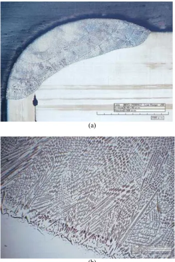
welded tube/tube sheet. Fig. 2a shows the cross-section of welded tube/tube sheet. Because of mechanical tube expansion, a crevice between the tube and tube sheet oc- curred (it should be noted that this crevice can’t be ex- posed to the corrosion solution because the other side was also seal-welded according to KS D0297 [9]). Fig. 2b con- firmed the dendritic microstructure of the weldment, and the throat thickness shows over 1 mm, which value sat- isfies the requirement of Article F-3 [11].
Fig. 3 shows the corrosion propagation path during pit- ting corrosion test of the autogeneous GTAW welded mock-up specimen. Fig. 3a reveals a corroded pit and se- lective pit growth can be confirmed around the large pit on the right side. We can find that this selective pit growth was closely related to the dendritic microstructure as shown in Fig. 3b.
4. Discussion
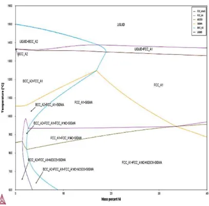
During the fusion welding process, the weldment was heated-up in a very short time, and then was melted, and thereafter was solidified, and cooled down in a few seconds. Since several chemical reactions between molten slag/melted metal, welding atmosphere/melted metal, and welding atmosphere/molten slag occurred at high temper- ature ranges, these reactions and the heating/cooling proc- ess could affect the microstructure of weldment. Fig. 4 shows the phase diagram of UNS32050 by nickel contents plotted using the Thermo-Calc® program and the red dot- ted line denotes the Ni content of the experimental alloy.
After the metal solidified, it can be seen that intermetallic compounds could be precipitated. During the cooling after (a)
(b)
Fig. 2 Microstructures of autogenous GTAW welded tube/tube sheet; (a) tube/tube sheet, and (b) weld bead (Optical microscope, 10wt% oxalic acid, 6 V, 10 seconds).
(a)
(b)
Fig. 3 Corrosion propagation path during pitting corrosion test of autogenous GTAW welded mock-up specimen; (a) SEM-BSE mode on corroded pit, and (b) SEM-BSE mode on corroded dendrite.
welding, sigma and kai phases, carbides and nitride could be formed depending upon the holding time.
Fig. 5a shows pitting corroded morphologies and bright areas formed ahead of the pit propagation path. These bright phases (ⓐ, ⓑ, ⓒ)as shown in Fig. 5b were con- firmed as (Cr, Mo) rich phase through EDS analysis. That
is, the dendrite areas were preferentially corroded, and in these areas (Cr, Mo) rich phases were precipitated.
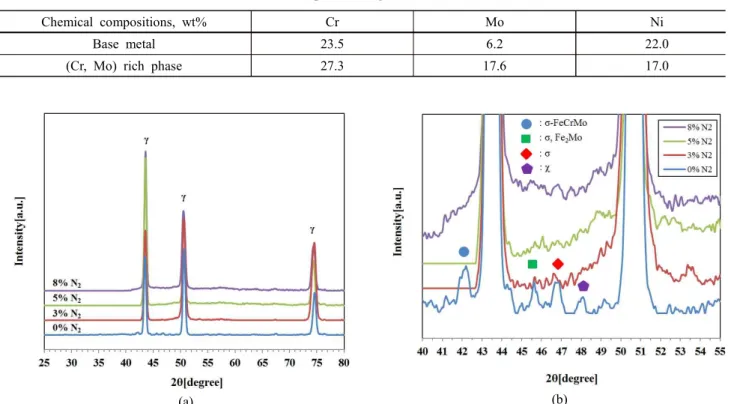
Table 2 summarizes the EPMA results of base metal and (Cr, Mo) rich phase in Fig. 5b. We performed the XRD analysis to identify the bright phase. Fig. 6 shows the effect of shielding gas on the formation of intermetallic Fig. 4 Phase diagram of UNS32050 by nickel contents plotted using the Thermo-Calc® program (red dotted line denotes the Ni content of the experimental alloy).
(a) (b)
Fig. 5 Pitting corroded morphologies and (Cr, Mo) rich phases formed ahead of the pit propagation path in the case of the specimen welded using 100% Ar shielding gas (SEM, BSE mode); (a) corroded area, (b) precipitation ahead the pit(red circle in (a)).
compounds at the weldment. The effect of shielding gas was not clear at the high scan speed of 4 o/min in XRD measurement as shown in Fig. 6a, but the several inter- metallic compounds were identified at the low scan speed of 1 o/min in Fig. 6b. Moreover, with increasing N2 gas concentration in the shielding gas, the intensities of the intermetallic compounds are being diminished gradually, but still existed [14]. The chai phase and sigma phase are typical (Cr, Mo) rich phases that are found frequently in stainless steels. It is well known that the chai phase forms before the sigma phase, and under prolonged aging it transforms to the sigma phase [15-17]. The chai phase is more enriched in Mo than is the sigma phase [15,18]
and so Mo tends to encourage chi formation. The sigma phase is Cr-enriched phase and because of its significant influence, the sigma phase has been researched for a very long time by a large number of workers [19-23].
Fig.s 3 and 5 show that pitting corrosion propagated preferentially along the dendritic structure. Thus, we per- formed the chemical composition on the dendrite arm and interdendrite areas. Fig. 7 shows the EPMA analysis points of the dendrite arm and interdendrite in the weldments by different shielding gas percent. The effect of shielding nitrogen gas was evaluated from the EPMA analysis. Fig.
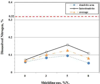
8 shows the effect of shielding nitrogen gas on nitrogen
contents in the dendrite arm and interdendrite of the weld- ments and in this Fig., the red dotted line denotes the nitro- gen content of the bulk specimen. Regardless of the shield- ing nitrogen gas percent, the analyzed nitrogen contents were very much lower than that of the bulk specimen.
This can be arisen because the nitrogen in shielding gas may partly dissolve into the weldment, but simultaneously during the welding process, nitrogen in the alloy may es- cape into the atmosphere. Nitrogen is one of the important elements to increase the localized corrosion resistance of the stainless steels. There are three ways in which nitrogen can dissolve in liquid iron: molecular, atomic, and ionic.
The nitrogen concentration remaining in the solidified weld metal represents a balance between N absorption, which is dominated by one of the faster processes - atomic or ionic and the evolution of nitrogen by bubble formation on, for example, inclusions [24].
However, with increasing shielding nitrogen gas per- cent, the analyzed nitrogen contents in the dendrite arm and interdendrite areas were increased but in 92% Ar+8%
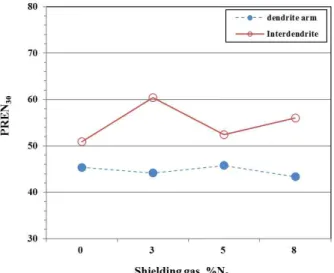
N2, it was slightly decreased. Therefore, using the EPMA analysis data from Fig. 7, we calculated the PREN of the dendrite arm and interdendrite areas. Fig. 9 shows the ef- fect of the shielding nitrogen gas on the PREN30 of den- drite arm and interdendrite areas calculated using chemical Table 2 EPMA results of base metal and (Cr, Mo) rich phase in Fig. 5(b)
Chemical compositions, wt% Cr Mo Ni
Base metal 23.5 6.2 22.0
(Cr, Mo) rich phase 27.3 17.6 17.0
(a) (b)
Fig. 6 Effect of shielding gas on the formation of intermetallic compounds at the weldment; (a) XRD scan speed 4o/min, and (b) XRD scan speed 1o/min.
compositions obtained by EPMA analysis. As identified at the above, the PREN of the interdendrite area was high- er than that of the dendrite arm regardless of the shielding gas percent. The PREN of the interdendrite area was high- er than that of the base metal, but the PREN of the dendrite arm was lower than that of the base metal. Finally, we compared the CPT between that obtained from the experi- ments, and that calculated from the composition on the dendrite arm using an eq. 1. Fig. 10 shows the results of the comparison. Even though the results of the experi- ments and the calculation were not coincident with each other, Fig. 10 can explain the CPT degradation by the welding process. Vilpas et al. reported the effect of the nitrogen content of shielding gas on the critical pitting temperature of a super austenitic stainless steel GTAW welds [25]. The results indicate that the CPT values of weld metal increase with increasing weld nitrogen content through the shielding gas. Similar results are also given by Hertman et al. [26], who reported a vast improvement in the pitting corrosion resistance of nitrogen containing
● Dendrite arm + Inter dendrite
(a) (b)
(c) (d)
Fig. 7 EPMA analysis points of dendrite arm and interdendrite in the weldments by different shielding gas percent; (a) 100% Ar, (b) 97% Ar+3% N2, (c) 95% Ar+5% N2, and (d) 92% Ar+8% N2.
Fig. 8 Effect of shielding nitrogen gas on nitrogen contents in the dendrite arm and interdendrite of the weldments (red dashed line depicts the nitrogen content of the bulk specimen).
GTA weld metals. In addition, Ogawa et al. [27] demon- strate that to utilize the effect of nitrogen on the pitting corrosion resistance of weld metal, it is effective to change the composition and enhance the nitrogen solubility of weld metal by adding elements, such as Mn to the filler metal. The effect of nitrogen in pitting corrosion resistance can be explained as follows [14]: 1) The formation of ammonia ion by nitrogen in pits/crevices consumes pro- tons, thereby leading to less severe reduction in the pH value [28-34] and the promotion of repassivation. In sul- fate solution, it has been propounded that ammonia ion
may form a protective, passive ammonium sulfate layer [35]. Ammonium has also been proposed to react with free chloride in chlorinated water, forming less oxidizing species [36]. Additionally, the rate of generation of ammo- nia ion increases proportionately with the nitrogen content of the alloys [28]. 2) The formation of corrosion-inhibiting nitrate and nitrite [32,37-40]. 3) The incorporation of ni- trogen into the surface passive film [41-45]. 4) Nitrogen is also believed to accumulate preferentially to active sites such as kinks and steps thereby hindering dissolution [46].
5) The repulsive action between chloride ion and neg- atively charged nitrogen that accumulates at the passive layer [33,47,48]. The repulsion of chloride ion gives rise to the fast repassivation of pits [49]. It has been suggested that negatively charged nitrogen may change into ammo- nium [49,50]. 6) Prevention of anion attack because of the enrichment of nitrogen at the film/substrate interface during passivation. Some authors have suggested that the formation of a stable protective layer of a Cr, Mn, N-rich nitride (Ni2Mo3N) is responsible for the protection [51-53], but Olefjord and Wergrelius [30] do not seem to endorse this notion. Alternatively, a layer of an inter- metallic phase beneath the passive film has been suggested to be the reason [50]. Olsson [54], besides finding N accu- mulation at the oxide/substrate interface, also detected N at the top of the passive layer. 7) Y. S. Kim [2] has sug- gested the synergistic effect of nitrogen and molybdenum on the localized corrosion of stainless steels: Nitrogen ex- ists as atomic nitrogen, nitric oxide, nitro-oxyanions, and N-H species, but not nitride in the passive film. Because of its high mobility, the enriched atomic nitrogen can act as a reservoir. The formation of N-H species buffers the film pH and facilitates the formation of oxyanions in the film. Nitro-oxyanions improve the cation selectivity of the film, increasing the oxide content and film density.
Nitro-oxyanions act similar to a strong inhibitor both in the passive film, and at active sites. This facilitates the formation of chromium oxide. Also, nitro-oxyanions can make more molybdate and nitric oxide by reacting with Mo. The coexistence of nitrogen and molybdenum in stainless steel drastically increases the corrosion resistance in chloride solutions.
That is, CPT degradation by the welding process came from the formation of intermetallic compounds and the evacuation of dissolved nitrogen in the alloy, but the shielding nitrogen gas improved the CPT.
4. Conclusions
1) The pitting corrosion resistance according to KS D0297 was determined for the seal-welded tube/tube sheet Fig. 9 Effect of shielding nitrogen gas on the PREN30 of the den-
drite arm and interdendrite areas calculated using the chemical compositions obtained by EPMA analysis.
Fig. 10 Comparison between the critical pitting temperatures ob- tained by pitting corrosion test and calculated by EPMA analysis on the dendrite arm and CPT-PRE relation Eq. (1) (red dashed line depicts the CPT of the base metal).
mock-up specimen for a sea water condenser, and the ef- fect of shielding nitrogen gas on its resistance was elucidated. CPT degradation by the welding process comes from the formation of intermetallic compounds and the evacuation of dissolved nitrogen in the alloy, but the shielding nitrogen gas improved the corrosion resistance.
2) The pitting corrosion of autogenously welded speci- men propagated preferentially along the dendritic structure. Regardless of the shielding nitrogen gas percent, the analyzed nitrogen contents were very much lower than that of the bulk specimen. This can arise because nitrogen in the shielding gas may partly dissolve into the weldment, but simultaneously during the welding process, nitrogen in the alloy may escape into the atmosphere. However, the PREN of the interdendrite area was higher than that of the dendrite arm, regardless of the shielding gas per- cent, and the PREN of the interdendrite area was higher than that of the base metal but the PREN of dendrite arm was lower than that of the base metal, because of the formation of (Cr, Mo) rich phases by welding.
Acknowledgement
This work was supported by a grant from the 2016 Research funds of Andong National University.
References
1. J. H. Oh, D. W. Yun, and H. Y. Chang, Power Eng., 21, 1 (2010).
2. Y. S. Kim, Corros. Sci. Tech., 9, 20 (2010).
3. I. S. Hwang, Industry and Energy, Report on the Corrosion Failure of Water Condenser of Uljin, pp. 15-28, NPP #5, Ministry of Commerce, Korea (2006).
4. N. Bailey, Weldability of Ferritic Steels, p. 18, Abington Publishing, Cambridge, England (1995).
5. U. Heubner and M. Rockel, Werstoffe und Korrosion, 37, 7 (1986).
6. M. B. Rockel, W. Herda, and U. Brill, Proc. Stainless steels ’91 conf., p. 78, Chiba, ISIJ, Japan (1991).
7. N. Suutala and M. Kurkela, Proc. Stainless Steels '84 conf., p. 240, The Metals Society, Gothenburg, London (1984).
8. H. J. Kim, S. H. Jeon, S. T. Kim, I. S. Lee, and Y. S.
Park, Corros. Sci. Tech., 13, 2 (2014).
9. KS D 0297, Test method for determination of pitting corro- sion resistance for seal weldment between tube and tube sheet (2009).
10. ASTM G48, Standard Test Methods for Pitting and Crevice Corrosion Resistance of Stainless Steels and Related Alloys by Use of Ferric Chloride Solution (2003).
11. ASME Code Section VIII, Division 2, Article F-3, Special Requirements for Tube-To-Tube sheet Welds (2004).
12. ASTM A 262, Standard Practices for Detecting Susceptibility
to Intergranular Attack in Austenitic Stainless Steels (2002).
13. Y. S. Kim, S. Park, and H. Y. Chang, Met. Mater. Int., 20, 69 (2014).
14. J. Ki. L. Lai, K. H. Lo, and C. H. Shek, Stainless Steels – An Introduction and Their Recent Developments, p. 96, Bentham Science Publishers, Sharjah (2012).
15. T. H. Chen, K. L. Weng, and J. R. Yang, Mater. Sci.
Eng. A, 338, 259 (2002).
16. J. Dobranszky, P. J. Szabo, T. Berecz, T. Berecz, V. Hrotko, and M. Portko, Spectrochim. Acta B, 59, 1781 (2004).
17. I. Calliari, M. Zanesco, and E. Ramous, J. Mater. Sci., 41, 7643 (2006).
18. J. Michalska and M. Sozanska, Mater. Charact., 56, 355 (2006).
19. C. J. Park, S. H. Kwon, and H. S. Kim, Corros. Sci. Tech., 2, 18 (2003).
20. T. Yamane, K. Suzuki, and Y. Minamino, J. Mater. Sci.
Lett., 4, 296 (1985).
21. J. Barcik, Mater. Sci. Technol., 4, 5 (1988).
22. M. Schwind, J. Kallqvist, J. O. Nilsson, J. Agren, and H. O. Andren, Acta Mater., 48, 2473 (2000).
23. Y. S. Sato and H. Kokawa, Scr. Mater., 40, 659 (1999).
24. U. K. Mudali and B. Raj, High Nitrogen Steels and Stainless Steels-Manufacturing, Properties and Applications, 1st ed., p. 205, Narosa Publishing House, ASM International, New Delhi (2004).
25. M. Vilpas and H. Hannien, Mater. Sci. Forum, 318-320, 603 (1999).
26. S. Hertman and S. Wessman, Mater. Sci. Forum, 318-320, 579 (1999).
27. T. Ogawa. K. Murata, S. Aoki, and E. Tsunetomi, J. Jap.
Weld. Soc., 49, 564 (1980).
28. G. C. Palit, V. Kain, and H. S. Gidayar, Corrosion, 49, 977(1993).
29. H. Baba, T. Kodama, and Y. Katada, Corros. Sci., 44, 2393 (2002).
30. I. Olefjord and L. Wergrelius, Corros. Sci., 38, 1203 (1996).
31. S. Azuma, H. Miyuki, and T. Kudo, ISIJ Int., 36, 793 (1996).
32. H. Yashiro, D. Hirayasu, and N. Kumagai, ISIJ Int., 42, 1477 (2002).
33. L. Vehovar, A. Vehovar, M. M. Hukovic, and M. Tandler, Mater. Corros., 53, 316 (2002).
34. W. T. Tsai, B. Reynders, M. Stratmann, and H. J. Grabke, Corros. Sci., 34, 1647 (1993).
35. C. R. Clayton, L. Rosenzweig, and M. Oversluizen, J.
Electrochem. Soc., 133, C303 (1986).
36. M. B. Ives, Y. C. Lu, and J. L. Luo, Corros. Sci., 32, 91 (1991).
37. R. C. Newman and M. A. A. Ajjawi, Corros. Sci., 26, 1057 (1982).
38. H. Baba and Y. Katada, Corros. Sci., 48, 2510 (2006).
39. H. Yashiro, D. Hirayasu, and N. Kumagai, ISIJ Int., 42, 1477 (2002).
40. T. Misawa and H. Tanabe, ISIJ Int., 35, 787 (1996).
41. J. E. Truman, M. J. Coleman, and K. R. Pirt, Br. Corros.
J., 12, 236 (1977).
42. S. Song, W. Song, and Z. Fang, Corros. Sci., 31, 395
(1990).
43. S. Ningshen, U. K. Mudali, and G. Amarendra, Corros.
Sci., 48, 1106 (2006).
44. A. S. Lim and A. Atrens, Appl. Phys. A, 51, 411 (1990).
45. U. K. Mudali, S. Ningshen, and D. K. Dayal, Bull.
Electrochem., 15, 74 (1999).
46. R. C. Newman and T. Shahrabi, Corros. Sci., 27, 827 (1987).
47. A. S. Vanini, J. P. Audouard, and P. Marcus, Corros. Sci., 36, 1825 (1994).
48. G. Lothongkum, P. Wongpanya, and S. Morito, Corros.
Sci., 48, 137 (2006).
49. A. Ahmed and A. Fathy, Ironmak. Steelmak., 59, 3311 (2005).
50. H. J. Garbke, ISIJ Int., 36, 777 (1996).
51. Y. Lu, R. Bandy, and C. R. Clayton, J. Electrochem. Soc., 130, 1774 (1983).
52. C. R. Clayton, G. P. Halada, and J. R. Kearns, Mat. Sci.
Eng. A, 198, 135 (1995).
53. I. Olefjord, B. Brox, and U. Jevelstam, J. Electrochem.
Soc., 132, 2854 (1985).
54. C. O. A. Olsson. Corros. Sci., 37, 467 (1995).