S
ince Bra�nemark and his colleagues1had intro- duced the concept of osseointegration, dental implants have been successfully used for fully and partially edentulous patients. The use of single implant has continued to increase and become refined.One of the common problems of single dental implant prostheses is the loosening of the screw,
and the problem is especially more common in external connection types.2-6 When it occurs, patients complain soreness at the interface between the soft tissue and the implant, swelling, and/or fistula formation, difficulty in mastication, and prosthetic instability.
From a biomechanical point of view, the 2 important methods used to counteract screw loosening, that is the incorporation of an anti-rota-
A STUDY OF THE EFFECT OF AN ANTI-
ROTATIONAL INNER POST SCREW SYSTEMS ON ABUTMENT SCREW LOOSENING FOR SINGLE IMPLANT : PART 1
Sun-Young Choi, D.D.S., M.S.D., Jai-Bong Lee, D.D.S., M.S.D., Ph.D.
Department of Prosthodontics, Graduate School, Seoul National University
Statement of problem.Implant abutment screw joints tend to loosen under clinical condi- tions. Abutment screw loosening results in loss of preload in function.
Purpose. Anti-rotational inner post screw (ARIPS) systems were compared with conventional abutment screws to reduce screw loosening. Reverse torque values were evaluated.
Material and methods. 32 implant assemblies (Warentec, Co, Ltd, Seoul, Korea) were organized as the 30-Ncm-torque conventional groups and 30-Ncm-torque ARIPS groups in exter- nal and internal system. The specimens were tested to 106cycles at a load of 200N. Preload reverse torque, postload reverse torque, and the ratio of postload reverse torque to preload reverse torque were evaluated. The data were analyzed with unpaired t-test in external and internal systems.
Results. In the ratio of postload reverse torque to preload reverse torque, the ARIPS groups showed significant differences than the conventional screw group in both external and inter- nal system.
Conclusion. Within the limitations of this study, abutment screw loosening was effective- ly reduced using ARIPS system.
Key Words
Dental implant, abutment screw loosening, anti-rotational inner post screw (ARIPS) system, reverse torque values
J Korean Acad Prosthodont : Volume 45, Number 3, 2007
tional elements and the screw joint preload.7 The two methods can be combined to reinforce each other.
As to the anti-rotational elements, Bra�nemark8 first introduced the implant external hexagon design. With the introduction of single-tooth implant-supported prosthesis, prosthesis index- ing and anti-rotational mechanisms have been added. And larger external hexagons, internal octagons, 1-degree Morse taper, frictional fit abutment, and the spline structure (close-sliding fit) were introduced. Bickford9reported on meth- ods to prevent screw loosening in vibration loos- ening by making slots, designing geared faces, and using lock wires or pins. Artzi et al10reported a screw lock method that a long hexagonal titani- um bar was inserted into the hexagon of a screw head, and resin fixed a screw. Cavazos and Bell11 advocated the application of hand torque, the addition of undercuts in the internal surface of the screw access chamber, and the injection of impres- sion material. Aboyoussef et al12 proposed a method that reduced screw loosening by making four milled notches around standard abutments.
The other important mechanical factor is the screw joint preload, which is defined as the ten- sile force that is built up in the abutment screw as a product of screw tightening.13,14It is depen-
dent on the applied torques and additionally on the component material, screw head and thread design, and surface roughness.13,15 The magni- tude of the torques is limited by the screw yield strength and the strength of the bone/implant inter- face.15,16
In this paper, the concept of post screw and lock- ing sleeve was introduced. The screw head was fabricated as a long post, so the inside of the abutment was filled. Notches were carved into the side of the post screw and corresponding abutment section. The resin-locking sleeve was located between the two notches. An implant assembly using a post screw was termed an anti-rotation- al inner post screw system, hereafter called an ARIPS system. This study used ARIPS systems to reduce the abutment screw loosening.
MATERIAL AND METHODS
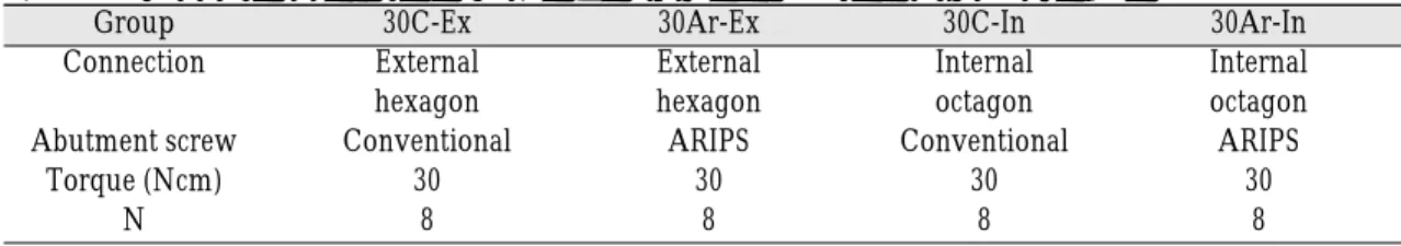
32 implant assemblies, 16 external hexagons and 16 internal octagons, were used (Table I). These assemblies were organized as the 30-Ncm-torque conventional screw groups (30C-Ex, 30C-In), 30- Ncm-torque ARIPS groups (30Ar-Ex, 30Ar-In) in external and internal systems. Each assembly was consisted of a 4.3 × 10 mm threaded, rough surface fixture (Warentec, Co, Ltd, Seoul, Korea),
Table I. Connection structure and tightening torque for specimen groups
Group 30C-Ex 30Ar-Ex 30C-In 30Ar-In
Connection External External Internal Internal
hexagon hexagon octagon octagon
Abutment screw Conventional ARIPS Conventional ARIPS
Torque (Ncm) 30 30 30 30
N 8 8 8 8
ARIPS = anti-rotational inner post system.
30C-Ex = 30Ncm torque-Conventional abutment screw-External hexagon group; 30Ar-Ex = 30Ncm torque-ARIPS screw-External hexagon group; 30C-In = 30Ncm torque-Conventional abutment screw-Internal octagon group;
30Ar-In = 30Ncm torque-ARIPS screw-Internal octagon group.
N = Number of specimens in each group.
6 mm abutment (Warentec, Co, Ltd), abutment screw, and superstructure jig (15 × 7 × 4 mm).
The abutment screws were conventional screws (Warentec, Co, Ltd) and newly designed ARIPS screws (Figs 1 and 2). The ARIPS screws were fab- ricated using the same titanium alloy used as conventional screws and were tightened with specially designed ARIPS screwdriver (Fig. 3). The superstructure jigs (Fig. 4) were manufactured with reinforced stainless steel and the internal diam- eter of central hole of the jig was milled within an
error of 0.01 mm. Thirty-degrees inclined planes were applied to both sides, to transfer lateral forces to implant assembly.
Fig. 1.Experimental ARIPS (anti-rotational inner post system) screws in internal octagons (left) and external hexagons (right).
Fig. 3. Experimental ARIPS (anti-rotational inner post system) screw driver, which screwed the implant deeply into a screw notch with two grooves.
Fig. 4. Experimental superstructure jig. Thirty-degrees inclined planes were applied to both sides to transfer lateral forces to implant assembly.
Fig. 2. Geometric dimensions of ARIPS (anti-rota- tional inner post system) screws of internal octagons (left) and external hexagons (right).
After applying a hand-tightening force on implant assembles, the specimens were embed- ded with clear resin (Ortho-Jet; Lang Dental Mfg. Co, Wheeling, Ill, USA) in a 20 × 20 × 30 mm mold using a surveyor. The resin was a polymethyl methacrylate resin exhibiting similar values in the modulus of elasticity to human trabecular bone (1.95 GPa).17The implants were placed so that 3 mm of bone resorption was sim- ulated18, and the surveyor was used to ensure that the implants were placed perpendicular to the base.
The fabrication process of an ARIPS resin-lock- ing sleeve is as follows: implant assembly was tight- ened with a target torque force. Tightening torque was applied, and according to a protocol suggested by Dixon et al19and Breeding et al,2010 minutes lat- er the screws were retightened to the same torque to minimize embedment relaxation. Then, the notch position was marked on the abutment.
Next, the implant assembly was separated (mea- suring preload reverse torques). Finally, notches on the abutment were formed using a high- speed diamond bur (Fig. 5). Tightening torque was reapplied and the composite resin (Heliomolar HB;
Ivoclar vivadent, Auckland, New Zealand) was filled in the locking sleeve (Fig. 6). Abutment screw tightening was applied using a digital torque gauge (MGT50; MARK-10 Corp, Copiague, NY). Because the torque controller recommend- ed by manufacturers could have resulted in dif- ferences in the tightening torque, the applica- tion of a precise tightening torque was attempt- ed using the digital torque gauge.
To apply cyclic loads, a universal testing machine (Fig. 7) was used at room temperature. This machine was an impact tester with a pressure gauge attached to the filter controller, to precisely measure and Fig. 5. ARIPS (anti-rotational inner post system) screw
notch. (A) 1.5cm (B) 2 cm.
Fig. 6. Sectional view of resin locking sleeve of ARIPS (anti-rotational inner post system) screw. The composite resin (Heliomolar HB) was filled in the locking sleeve.
Fig. 7. Universal testing machine. This machine was an impact tester with a pressure gauge attached to the fil- ter controller, and included load cells.
control the fluid pressure. The loading system included load cells (Loadcell DBBP-100; Bongshin Loadcell Co, Seongnam, Korea) attached for the purpose of measuring applied loads and detect- ing any changes in load.
200 N of cyclic load was applied and load was limited to a tolerance of within 10%. 18 Richter et al 21reported that the maximum occlusal force of implant prostheses for a molar region was 121.1
±69.6 N. The loading force of this study was within the range of posterior occlusal force for fixed prostheses supported by implants (35-330 N).22The loading stylus was cone shaped, made of stainless steel, and had a 3 mm diameter hemisphere tip.
The loading rate was 0.87 Hz and the number of cycles was 1.0× 10⁶. A target of 106cycles could be estimated 1 year of simulated function. This esti- mation was that a person has 3 episodes of mas- tication per day, each 15 minutes in duration at a masticatory rate of 60 cycles per minute (1 Hz). This is equivalent to 2,700 cycles per day, roughly 106per year.
Postload reverse torque was measured using a digital torque gauge under the jig-assembled conditions. The process that the jig held the sleeve to the side was considered similar as that the prosthesis was clinically attached to an abut-
ment.
SPSS Statistical Software for Windows (release 12.0, SPSS, Chicago, Ill, USA) was used for statistical analysis. Preload reverse torque, postload reverse torque, and the percentage of postload reverse torque to preload reverse torque were evaluated.
The data were analyzed with unpaired t-test in external and internal systems (P<. 05).
RESULTS
Preload reverse torque and postload reverse torque values were evaluated (Table II and III).
4 screws (3 conventional screws, 1 ARIPS screws) were fractured during load application at the interface between the screw shank and the first thread.
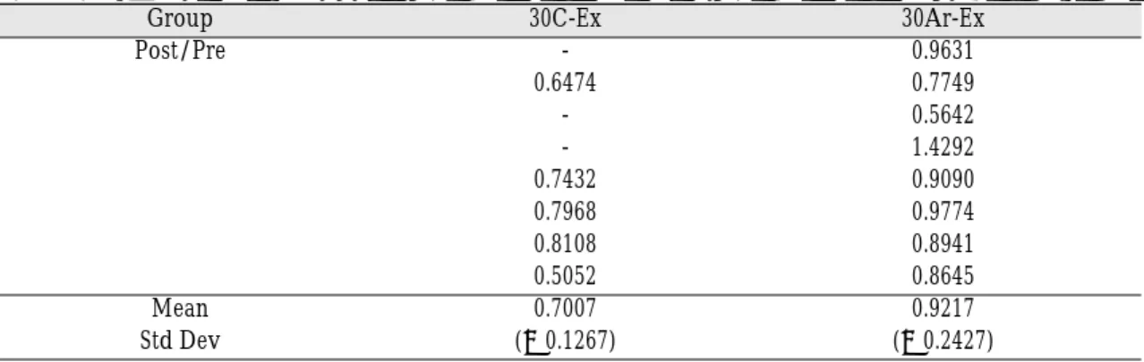
The ratio of post load reverse torque to preload reverse torque in external system was estab- lished (Table IV) and statistical results of unpaired t- test were established (Table V). There are sig- nificant differences between the conventional screw group and ARIPS group in external system (P<. 05). And the ratio of post load reverse torque to preload reverse torque in internal system was established (Table VI) and statistical results of unpaired t- test were established (Table VII).
Table II. Preload reverse torque values of specimens (Ncm)
Group 30C-Ex 30Ar-Ex 30C-In 30Ar-In
Preload torque 27.2 24.4 27.6 27.2
27.8 27.1 26.7 25.7
29.1 31.9 31.7 32.0
23.8 24.2 31.2 27.5
29.6 27.5 27.9 27.2
25.1 26.6 28.6 28.8
29.6 27.4 25.5 29.2
28.7 26.6 27.3 27.6
30C-Ex = 30Ncm torque-Conventional abutment screw-External hexagon group; 30Ar-Ex = 30Ncm torque-ARIPS screw-External hexagon group; 30C-In = 30Ncm torque-Conventional abutment screw-Internal octagon group; 30Ar- In = 30Ncm torque-ARIPS screw-Internal octagon group.
Table V. The results of Unpaired t-test in external groups
Group N Mean Std Dev Std Error T DF P
30C-Ex 5 0.701 0.127 0.057 -2.15 10 .0290*
30Ar-Ex 8 0.922 0.244 0.086 -2.15 10
30C-Ex = 30Ncm torque-Conventional abutment screw-External hexagon group; 30Ar-Ex = 30Ncm torque-ARIPS screw-External hexagon group.
* = significantly different (P<0. 05).
Table IV. The percentage of postload reverse torque to preload reverse torque in external groups
Group 30C-Ex 30Ar-Ex
Post/Pre - 0.9631
0.6474 0.7749
- 0.5642
- 1.4292
0.7432 0.9090
0.7968 0.9774
0.8108 0.8941
0.5052 0.8645
Mean 0.7007 0.9217
Std Dev (±0.1267) (±0.2427)
30C-Ex = 30Ncm torque-Conventional abutment screw-External hexagon group; 30Ar-Ex = 30Ncm torque-ARIPS screw-External hexagon group.
Post/ Pre = postload reverse torque/ preload reverse torque.
- : Abutment screws were fractured during cyclic loading procedures.
Table III. Postload reverse torque values of specimens (Ncm)
Group 30C-Ex 30Ar-Ex 30C-In 30Ar-In
Postload torque - 23.5 17.5 22.5
18.0 21.0 8.5 33.5
- 18.0 27.0 22.5
- 34.5 14.5 27.5
22.0 25.0 15.0 19.5
20.0 26.0 21.5 25.5
24.0 24.5 16.5 -
14.5 23.0 16.5 21.0
30C-Ex = 30Ncm torque-Conventional abutment screw-External hexagon group; 30Ar-Ex = 30Ncm torque-ARIPS screw-External hexagon group; 30C-In = 30Ncm torque-Conventional abutment screw-Internal octagon group; 30Ar- In = 30Ncm torque-ARIPS screw-Internal octagon group.
- : Abutment screws were fractured during cyclic loading procedures.
There are significant differences between the conventional screw group and ARIPS group in internal system (P<. 05). The 30-Ncm-toruqe ARIPS groups showed significant differences than the 30-Ncm-toruqe conventional screw groups in both external and internal systems.
DISCUSSION
The ratio of postload reverse torque to pre- load reverse torque was clinically important ref- erences to prevent the loss of preload. In the ratio of postload reverse torque to preload reverse torque, the external and internal groups with the ARIPS system displayed significant differences
than conventional screw groups.
Based on the estimated results, the ARIPS sys- tem presented superior results under the same pre- load conditions to the conventional screw after load- ing. The reason of the efficacy of ARIPS systems might be that the ARIPS screw was fitted with a long post that expanded the contact area to the abut- ment, and the presence of the locking sleeve cre- ated a more stable engagement of anti-rotational element and an increased moment arm.
A few number of abutment screws were frac- tured during load application at the interface between the screw shank and the first thread. This result coincided with a report on stress distribution of preloaded screws by Alkan et al in 2004.23 Table VI. The percentage of postload reverse torque to preload reverse torque in internal groups
Group 30C-In 30Ar-In
Post/Pre 0.6340 0.8272
0.3148 1.3035
0.8517 0.7031
0.4647 1.0000
0.5376 0.7169
0.7517 0.8854
0.6470 -
0.6043 0.7608
Mean 0.6012 0.8853
(±0.1653) (±0.2115)
30C-In = 30Ncm torque-Conventional abutment screw-Internal octagon group; 30Ar-In = 30Ncm torque-ARIPS screw- Internal octagon group.
- : Abutment screws were fractured during cyclic loading procedures.
Table VII. The results of Unpaired t-test in internal groups
Group N Mean Std Dev Std Error T DF P
30C-In 8 0.601 0.166 0.059 -2.87 11
.0008**
30Ar-In 7 0.885 0.212 0.080 -2.87 11
30C-In = 30Ncm torque-Conventional abutment screw-Internal octagon group; 30Ar-In = 30Ncm torque-ARIPS screw-Internal octagon group.
** = significantly different (P<0.01).
In the previous stage of the experiment, the differences of the notch joints between the hand tightening and the mechanical tightening were happened. The broader abutment notch than screw notch can guarantee a locking area. To maximize the effect of ARIPS screw, additional studies, on size of a notch and strength of locking resin, are required.
Reverse torque values were not evaluated in clin- ical trials, so there are limitations of this method in applications. And it was necessary to reex- amine the effect on the abutment screw when it was retightened. Weiss et al24reported that repeat- ed opening and closing of abutment screws caused progressive loss of torque retention.
Tzenakis et al25reported that in gold prosthetic screw with repeated torque tightening, the grad- ual elimination of micro roughness and allowed a greater amount of preload. Further studies are required on the effects of repeated torque tight- ening on a titanium abutment screws.
CONCLUSION
Within the limitations of this study, the fol- lowing conclusions were drawn:
1. There were significant differences in reverse torque values between the conventional screw groups and ARIPS groups after cyclic loadings.
2. In the percentage of postload reverse torque to preload reverse torque, The 30-Ncm-toruqe ARIPS groups showed significant differences than the 30-Ncm-toruqe conventional screw groups in external system.
3. In the percentage of postload reverse torque to preload reverse torque, The 30-Ncm-toruqe ARIPS groups showed significant differences than the 30-Ncm-toruqe conventional screw groups in internal system.
REFERENCES
1. Adell R, Lekholm U, Bra�nemark PI. A 15-year study of osseointegrated implants in the treat- ment of the edentulous jaw. Int J Oral Surg 1981;10:387-416.
2. Binon PP. The effect of implant/abutment hexag- onal misfit on screw joint stability. Int J Prosthodont 1996;9:149-160.
3. Jemt T, Linden B, Lekholm U. Failures and com- plications in 127 consecutively inserted fixed pros- theses supported by implants: From prostheses treat- ment to first annual check up. Int J Oral Maxillofac Implants 1992;7:40-43.
4. Jemt T. Failures and complications in 391 con- secutively inserted fixed prostheses supported by implants in edentulous jaws: A study of treat- ment from the time of prosthesis placement to the first annual checkup. Int J Oral Maxillofac Implants 1991;6:270-276.
5. Jemt T. Multicenter study of overdentures supported by Bra�nemark. Int J Oral Maxillofac Implants 1992;7:513-522.
6. Becker W, Becker B. Replacement of maxillary and mandibular molars with single endosseous im- plants restorations: a retrospective study. J Prosthet Dent 1995;74:51-5.
7. Khraisat A, Hashimoto A, Nomura S, and Miyakawa O. Effect of lateral cyclic loading of abutment screw loosening of an external hexa- gon implant system. J Prosthet Dent 2004;91:326- 34.
8. Binon PP. Implants and components: entering the new millennium. Int J Oral Maxillofac Implants 2000;15:76-94.
9. Bickford JH. An introduction of the design and be- havior of bolted joints. New York Marcel Dekker Inc. 1981:248-76.
10. Artzi Z, Dreiangel A. Securing the abutment post screw in single implant prosthesis. J Prosthet Dent 1997;78:432-3.
11. Cavazos E, Bell FA. Preventing loosening of implant abutment screws. J Prosthet Dent 1996;76:566-9.
12. Aboyoussef H, Weiner S, Ehrenberg D. Effect of an antirotation resistance form on screw loosening for single implant-supported crowns. J Prosthet Dent 2000;83:450-5.
13. Jorneus L, Jemt T, Carlsson L. Loads and design of screw joints for single crowns supported by os- seointegrated implants. Int J Oral Maxillofac Implants 1992;7:353-9.
14. Rangert B, Jemt T, Jorneus L. Forces and moment on Bra�nemark implants. Int J Oral Maxillofac Implants 1989;4:241-7.
15. McGlumphy EA, Mendel DA, Holloway JA.
Implant screw mechanics. Dental Clin North Am 1998;2:71-89.
16. Tjellstrom A, Jacobsson M, Albrektsson T. Removal torque of osseointegrated craniofacial implants: a clinical study. Int J Oral Maxillofac Implants 1988;3:287-9.
17. Larson WR, Dixon DL, Aquilino SA, Clancy JM. The effect of carbon graphite fiber reinforcement on the strength of provisional crown and fixed partial den- ture resins. J Prosthet Dent 1991;66:816-20.
18. ISO/DIS 14801 Dental implants-Dynamic con- tinuous fatigue test, International Organization for Standardization, 2001.
19. Dixon DL, Breeding LC, Sadler JP, McKay ML.
Comparison of screw loosening, rotation, and de- flection among three implant designs. J Prosthet Dent 1995;74:270-8.
20. Breeding LC, Dixon DL, Nelson EW, Tietge JD.
Torque required loosening single-tooth implant abut- ment screws before and after simulated function.
Int J Prosthodont 1993;6:435-9
21. Richter EJ. In vivo vertical forces on implants.
Int J Oral Maxillofac Implants 1995;10:99-108.
22. Mericske-Stern R, Zarb GA. In vivo measure- ments of some functional aspects with mandibu-
lar fixed prostheses supported by implants. Clin Oral Imp Res 1996;7:153-61.
23. Alkan I, Sertgoz A, Ekici B. Influence of occlusal forces on stress distribution in preloaded dental im- plant screws. J Prothet Dent 2004;91:319-25.
24. Weiss EI, Kozak D, Gross MD. Effect of repeated closures on opening torque values in seven abut- ment-implant systems. J Prosthet Dent 2000;84:194- 9.
25. Tzenakis GK, Nagy WW, Fournelle RA, Dhuru VB.
The effect of repeated torque and salivary conta- mination on the preload of slotted gold implant prosthetic screws. J Prosthet Dent 2002;88:183- 91.
Reprint request to:
JAE-BONGLEE, D.D.S., M.S.D., PH.D.
DEPARTMENT OFPROSTHODONTICS,GRADUATESCHOOL,SEOUL NATIONALUNIVERSITY
28 YONKUN-DONG,CHONGRO-GU, SEOUL,110-749, KOREA [email protected]