1. 서 론
국내에서 개발 중인 일체형 원자로인 SMART (system-integrated modular advanced reactor)는 증기
발생기 원자로냉각재 펌프 가압기 등 내부기기들, , 이 원자로 용기 내부에 설치되는 설계 특성상 원 자로 압력용기에 다수의 노즐이 존재한다.(1) 이러
한 다수의 노즐 중 몇몇 노즐은 저합금강-Alloy 계열 니켈기 합금 오스테나이트 스테인리스 강
690 -
의 조합으로 구성된 이종금속 용접부가 위치하게 된다. Alloy 690 계열 니켈기 합금은 Alloy 600 계 열보다 응력부식균열(PWSCC: primary water stress 에 대한 저항성이 우수한 합금으 corrosion cracking)
로 아직까지 응력부식균열이 발생된 사례가 보고 된 바 없다.(2) 이러한 이종금속 용접부는 예민화 현상 때문에 일반적으로 용접 후열처리를 수행하 학술논문
< >
DOI http://dx.doi.org/10.3795/KSME-A.2012.36.6.599
ISSN 1226-4873일체형 원자로 안전주입 노즐 이종금속 용접부에 대한 레이저 피닝 적용의 수치 해석적 연구
서중현* · 김종성* · 정명조** · 류용호**
순천대학교 기계공학과 한국원자력안전기술원
* , **
A Numerical Analysis on Application of Laser Peening to Dissimilar Metal Welds in a Safety Injection Nozzle of Integral Reactor
Joong Hyun Seo* , Jong Sung Kim* , Myung Jo Jhung** and Yong Ho Ryu**
* Dept. of Mechanical Engineering, Sunchon Nat’l Univ., ** Korea Institute of Nuclear Safety (Received May 3, 2011 ; Revised March 13, 2012 ; Accepted March 28, 2012)
Key Words: Laser Peening(레이저 피닝), Welding Residual Stress(용접 잔류응력), Dissimilar Metal Welds
이종 금속 용접부 동적 유한요소 해석
( ), Dynamic Finite Element Analysis( )
초록 일체형 원자로의 안전주입 노즐 이종금속 용접부의 잔류응력에 대한 레이저 피닝의 효과를 고찰: 하기 위해 상용 프로그램인 ABAQUS를 이용하여 implicit 동적 유한요소 해석을 통해 연구를 수행하였 다. implicit 동적 유한요소 해석은 기존의 실험 결과와의 비교에 따르면 레이저 피닝을 통한 잔류응력 이완에 대해 타당하다고 확인된다 한편 내부 보수용접이 수행된 이종금속 용접부에 대해 해석이 수행. 되며 그 결과는 축방향 및 원환 잔류응력 모두 내부 보수용접에 기인하여 노즐의 내표면에서 인장임을 나타낸다 또한 용접 잔류응력 이완에 대한 최대 충격 압력 압력 지속 시간 스폿 직경 및 피닝 방향과. , , 같은 여러 변수의 효과를 고찰하기 위해 변수 해석 또한 수행하였다 결과적으로 레이저 피닝은 내표. , 면 근처 영역의 잔류응력을 주로 이완시키는 예방정비 효과가 있음을 확인하였다.
Abstract: A numerical analysis has been performed through implicit dynamic finite element analysis using the commercial package, ABAQUS in order to investigate effect of laser peening on welding residual stress mitigation of dissimilar metal welds in a safety injection nozzle of integral reactor. The implicit dynamic finite element analysis are compared with the previous experimental results. By comparison, it is identified that the implicit dynamic finite element analysis is valid for residual stress mitigation via laser peening. Implicit static finite element residual stress analysis has been performed for the dissimilar metal welds subject to inner repair welding. The analysis results represent that both axial and hoop residual stresses are tensile on inner surface of safety injection nozzle due to inner repair welding. Also Parametric study has performed to investigate effect of laser peening variables such as maximum impact pressure, duration time of pressure, spot diameter and peening direction on the welding residual stress mitigation. As a result, it is found that laser peening has the preventive maintenance effect to mitigate mainly residual stresses of region near inner surface.
Corresponding Author, [email protected] 2012 The Korean Society of Mechanical Engineers
Ⓒ
단축시킬 뿐만 아니라 균열 발생 시 균열 진전 구 동력의 주요 인자로 작용하게 된다.(7,8) 따라서 일 체형 원자로 안전주입 노즐 이종금속 용접부에 내 면 보수용접을 수행하여 인장 잔류응력이 높게 발 생하게 된 경우에는 잔류응력을 이완시키기 위한 효율적인 수단의 적용이 필요하다 인장 잔류응력. 이완 방법들로는 PWOL(pre-emptive weld overlay), 레이저 피닝(laser peening), MSIP(mechanical stress
워터 제트 피닝
improvement process), (water jet peening), IHSI(induction heating stress improvement) 등이 있는데 공정시간이 짧고 열에너지 원이 필요 없으며 전체적인 소성변형과 미세조직 변화를 야 기 시키지 않는 레이저 피닝을 본 연구의 예방정 비 방안으로 삼고자 한다.
김종성 등은 용접 구조물의 사용중 적합성 평 가를 위한 잔류응력 유한요소 해석절차를 검증 개발하였으며,(9) 개발한 절차를 원전 가압기 노즐 이종금속 용접부에 적용하여 축방향 잔류응력 분 포에 대한 공학적 수식을 개발한 바 있다.(10) 송 태광 등은 원전 노즐 이종금속 용접부의 잔류응 력 예측을 위한 Round Robin 해석을 수행하여 잔 류응력 해석의 합리적인 타당성을 확인한 바 있 다.(11) Nam은 레이저 피닝에 의해 모재에 부가되 는 잔류응력 현상을 유한요소 해석을 통해 보여 주었으며,(12) DeWald 등은 변위 측정과 유한요소 해석을 이용한 contour 방법을 통해 레이저 피닝 에 의한 Alloy 22 용접부의 인장 잔류응력 이완 거동의 평가를 수행하였다.(13) Sano 등은 비등경 수로 오스테나이트 용접부와 가압경수로 이종금 속 용접부의 잔류응력 이완을 위해 적용할 수 있 는 레이저 피닝 방안을 개발하였다.(14) 그러나 레 이저 피닝이 원전 설비 이종금속 용접부에 적용 시 잔류응력이 이완되는 효과를 체계적으로 해석 한 연구는 찾아보기 힘들다.
본 연구에서는 일체형 원자로의 안전주입 노즐 이종금속 용접부의 용접 잔류응력에 대한 레이저 피닝의 효과를 고찰하기 위해 상용 프로그램인
최종적으로 용접 잔류응력 이완에 대한 최대 충격 압력 압력 지속 시간 스폿 직경 및 피닝 방향과, , 같은 레이저 피닝 변수의 효과를 고찰하기 위해 해 당 변수에 대한 해석을 수행하였다.
동적 유한요소 해석 검증 2.
검증 해석 대상 2.1
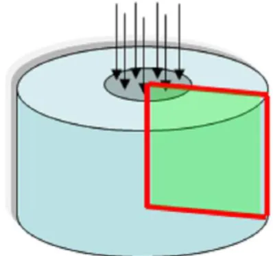
은 레이저 피닝을 통한 잔류응력 완화에 Fig. 1
대한 implicit 동적 유한요소 해석의 타당성을 검 증하기 위한 단일 레이저 펄스와 용접부가 없는 지름 30 mm, 높이 15 mm의 35CD4 30 HRC 합 금강 밀도( : 7800 kg/m3, 탄성계수 : 210 GPa, 프 와송 비 : 0.29, 항복강도 : 0.87 GPa)의 축대칭 모델이다.(16) Fig. 2는 실험을 통해 도출한 압력 변화와 전산 모사를 위해 사용한 압력 변화를 보 여주고 있다.(16) Fig. 3은 유한요소 모델을 제시하 고 있다 사용한 유한요소는. CAX4R(4-node bilinear axisymmetric quadrilateral, reduced integration, hourglass control)와 CINAX4(4-node linear axisym- metric one-way infinite quadrilateral)로서 절점 수와 요소 수는 각각 91,202개와 90,600개다 모든 요소를. 로만 구성하여 해석하면 막대한 계산시간 CAX4R
이 소요되므로 효율적인 해석을 위해 CAX4R과
를 혼용하였다 를 이용하여
CINAX4 . ABAQUS Implicit
Fig. 1 Configuration of the axisymmetric model with a single laser pulse and no weld
(a) Experimental results
(b) Used in simulation (I=4GW/cm2)
Fig. 2 Pressure-time history of a single pressure pulse on the specimen surface
Fig. 3 Finite element model of the axisymmetric model with a single laser pulse and no weld
동적 유한요소 해석을 수행하였다. ABAQUS의 경우 수치적 감쇄 제어 변수(numerical damping control parameter) 의 값은-0.05로 기본설정 되어 있다.
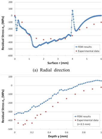
(a) Radial direction
(b) Depth direction (radial distance r=3.5 mm) Fig. 4 Comparison of FEM result with the previous
study results
검증 결과 2.2
는 해석 결과 반경방향 잔류응력 분포 를
Fig. 4 ( )
기존 실험(16)과 비교한 결과를 제시하고 있다 일. 부 표면 영역 (r=4 mm 근처 에서 반경방향 잔류) 응력 값이 튀는 해석결과를 도출하나 실험은 특 정 위치에서만 측정하기 때문에 이러한 튀는 현 상을 도출할 수 없다 실험 결과와 비교 시 실험. 결과와 합리적으로 잘 일치함을 알 수 있다 따. 라서 implicit 동적 유한요소 해석은 레이저 피닝 을 통한 잔류응력 이완을 신뢰성있게 모사할 수 있다고 확인되었다.
이종금속 용접부의 잔류응력에 미치는 3.
레이저 피닝의 영향 고찰
본 해석 대상 3.1
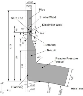
는 본 연구의 해석 대상인 일체형 원자로 Fig. 5
안전주입 노즐 이종금속 용접부의 형상을 제시하 고 있다 일체형 원자로의 경우 아직 구체적인. ,
Fig. 5 Configuration of the dissimilar welds in a safety injection nozzle of systematically integral reactor
용접부 형상이 설계된 상태가 아니므로 기존의 상용 원전 1차측 기기 노즐의 이종금속 용접부를 참조하여 설계하였다 각 부위별 재질로는 노즐. 은 SA508 Gr.3, Cl.1, 버터링과 버터링 안전단의- 용접금속은 Alloy 52/152, 안전단은 SA182 F316, 클래딩과 안전단 배관의 용접금속은- ER308, 배관 은 SA376 TP316이 사용된다고 가정하였다 내면. 보수용접을 실시하지 않으면 노즐 내면에 인장 잔류응력이 크게 발생하지 않으므로 본 평가에서 는 내면 보수용접을 수행하였다고 가정하였다.
온도 및 응력 해석에 사용된 재료물성치는 ASME B&PV Code, Sec. II, Part D,(17) 기존의 연
구자료(18~20) 및 재료공급자가 제공한 값(21)을 사용
하였고 밀도는 온도에 무관하게 일정하게 설정하 였으며 (F316은 7.71×10⁻⁶ kg/mm3, TP316은 7.97×10⁻⁶ kg/mm3, ER308은 8.01×10⁻⁶ kg/mm3, Alloy 52/152는 8.47×10⁻⁶ kg/mm3, SA508 Gr.3, Cl.1은 7.83×10⁻⁶ kg/mm3) 온도에 따른 밀도의 변 화는 온도에 따른 비열 변화에 반영하였다 프와. 송 비는 온도에 무관하게 일정한 값들을 갖도록 설정하였다(F316은 0.27, TP316과 ER308은 0.294,
는 를 은
Alloy 52/152 0.324 , SA508 Gr.3, Cl.1 0.29
본 해석에서는 내면 보수용접 잔류응력 해석을 우선적으로 수행한 후 레이저 피닝 방안 적용에 따른 잔류응력 해석을 수행하였다 따라서 경계. 조건은 내면 보수용접 및 레이저 피닝 방안 적용 의 각 경우에 대해 제시하였다.
내면 보수용접의 경우 그루브 부위는 용접금, 속의 용착 동안에는 단열상태로 가정하였다 한. 편 용접금속은 액상선 온도보다 높은 1500℃ 정 도의 높은 온도로 용착된다고 가정하였다 용착. 시 입열량은 용접시방서 상의 전압 전류 값들을, 식 (1), (2)에 대입하여 계산된 값이 용착시간 동 안 작용한다고 가정하였다.
(1)
(2)
여기서 는 용접 패스 체적에 작용하는 체적 열유속(J/m3sec), 는 용접 패스가 용착되는 표 면에 작용하는 표면 열유속(J/m2sec), V는 단위 용 접 패스당 체적(m3), A는 단위 용접 패스당 표면 열유속이 가해지는 표면적(m2)이다. 는 효율, E 는 전압, I는 전류이다.
배관 끝단면은 배관 중심점과 x, y방향 (Fig. 5 에 제시 변위의 자유도를 연계시켰으며) x, y, z 방향 모멘트가 발생하지 않는다고 가정하였다.
원자로 압력용기 절단면은 y방향 변위를 구속시 켰다.
은 레이저 피닝 적용시 작용하는 충격 Fig. 6
하중이 작용하는 경계조건을 제시하고 있다 이. 러한 충격하중은 최대 압력 6GPa로 Fig. 7과 같 이 작용하며 레이저 스폿 크기는 직경 2mm 정도 로 가정하였다.(24,25)
유한요소 모델링 3.2
은 온도 및 잔류응력 해석을 위해
Fig. 8 ABAQUS
Fig. 6 Boundary condition of impact pressure during laser peening
Fig. 7 Normalized impact pressure variation during laser peening
를 이용하여 모델링한 축대칭 유한요소 모델이 다 유한요소 모델은 요소특성이 각각. 4절점 요 소이다 용접부는 좀 더 세밀하게 유한요소 모델. 링을 수행하였다. Fig. 8에 제시한 바와 같이 내 면 보 수 용 접 패 스 는 8패 스 로 모 델 링 하 였 다.
잔류응력 해석 및 레이저 피닝 효과 평가 3.3
용접 구조물의 사용중 적합성 평가를 위한 잔 류응력 해석절차(9)를 적용하여 내부 보수용접 이 후 잔류응력 분포를 도출한다. ABAQUS를 이용, 열전도 기반 온도해석 및 implicit한 축대칭 이차 원 탄소성 유한요소 응력해석을 수행한다 내면. 보수용접은 정적 해석을 수행하였으며 레이저 피 닝은 동적 해석을 수행하였다.
는 내면 보수용접 이후의 잔류응력 분포 Fig. 9
를 제시하고 있다. Fig. 9로부터 축방향 및 원환
Fig. 8 Axisymmetrical finite element model of the dissimilar welds in a safety injection nozzle of systematically integral reactor
(a) Axial (b) Hoop Fig. 9 Residual stress distributions after inner
repair welding
잔류응력 모두 내부 보수용접에 기인하여 안전주 입 노즐의 내표면에서 인장임을 알 수 있다. Fig.
은 레이저 피닝 적용 이후의 잔류응력 분포를 10
제시하고 있다. Fig. 9와 10을 상호 비교하면 다 음과 같은 사실을 도출할 수 있다.
레이저 피닝은 내표면의 잔류응력을 저감하는
◦
예방정비 효과가 있음
레이저 피닝은 주로 내표면 근처 영역의 잔류
◦
응력을 저감시킴
은 레이저 피닝 방안 적용에 따른 내표 Fig. 11
(a) Axial (b) Hoop Fig. 10 Residual stress distributions after laser
peening
(a) Axial
(b) Hoop
Fig. 11 Variation of residual stress distributions along inner surface
면 선 상의 잔류응력 분포 변화를 보여주고 있 다. Fig. 11에서 보이는 바와 같이 레이저 피닝 적용시 내표면의 잔류응력은 축방향 원환 응력,
(a) Axial
(b) Hoop
Fig. 12 Variation of residual stress distributions along welding center line
모두 상당히 저감하는 경향을 보인다.
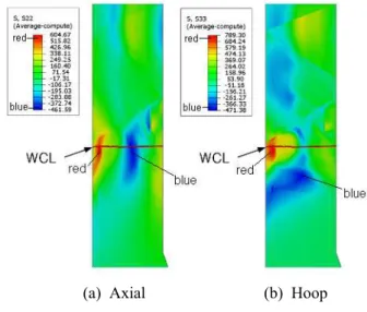
는 레이저 피닝 방안 적용에 따른 내면 Fig. 12
보수용접 중앙선 (WCL : weld center line) 상의 잔류응력 분포 변화를 보여주고 있다. WCL은
에 제시되고 있다 에서 보이는 바와
Fig. 9 . Fig. 12
같이 레이저 피닝 적용시 주로 내표면 쪽의 잔류 응력이 저감된다.
잔류응력 이완에 미치는 레이저 피닝 변수 3.4
의 영향 고찰
은 레이저 피닝 변수의 영향을 고찰하 Table 1
기 위한 변수 해석에 사용된 각각의 변수 값들을 제시하고 있다.
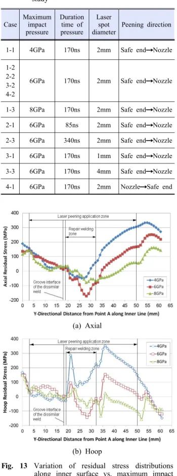
은 최대 충격압력 변화에 따른 내표면 Fig. 13
상의 잔류응력 분포 변화를 보여주고 있다. Fig.
는 최대 충격압력 변화에 따른 내면 보수용접 14
중앙선 상의 잔류응력 분포 변화를 보여주고 있 다. Fig. 13과 14에서 보이는 바와 같이 최대 충 격압력이 증가할수록 내면 보수용접 영역의 내표
Case
Maximum impact pressure
Duration time of pressure
Laser spot diameter
Peening direction
1-1 4GPa 170ns 2mm Safe end Nozzle 1-2
2-2 3-2 4-2
6GPa 170ns 2mm Safe end Nozzle
1-3 8GPa 170ns 2mm Safe end Nozzle 2-1 6GPa 85ns 2mm Safe end Nozzle 2-3 6GPa 340ns 2mm Safe end Nozzle 3-1 6GPa 170ns 1mm Safe end Nozzle 3-3 6GPa 170ns 4mm Safe end Nozzle 4-1 6GPa 170ns 2mm Nozzle Safe end
Table 1 Laser peening variables for the parametricstudy
(a) Axial
(b) Hoop
Fig. 13 Variation of residual stress distributions along inner surface vs. maximum impact pressure
면에서의 이완효과는 증가하다가 감소하며 이완 이 발생하는 영역 깊이는 증가함을 알 수 있다.
는 충격압력 지속시간 변화에 따른 내표 Fig. 15
면 상의 잔류응력 분포 변화를 보여주고 있다.
은 충격압력 지속시간 변화에 따른 내면보 Fig. 16
수용접 중앙선 상의 잔류응력 분포 변화를 보여 주고 있다. Fig. 15와 16에서 보이는 바와 같이 충격압력 지속시간이 증가할수록 내표면에서의 이완효과는 증가하며 이완이 발생하는 영역의 깊 이도 증가함을 알 수 있다.
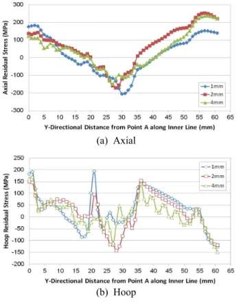
은 레이저 스폿 직경 변화에 따른 내표 Fig. 17
면 상의 잔류응력 분포 변화를 보여주고 있다.
은 레이저 스폿 직경 변화에 따른 내면 보 Fig. 18
수용접 중앙선 상의 잔류응력 분포 변화를 보여 주고 있다. Fig. 17과 18에서 보이는 바와 같이 레이저 스폿 직경은 최대 충격 압력과 충격 압력 지속시간에 비해 상대적으로 미미한 영향을 주고 있음을 알 수 있다.
(a) Axial
(b) Hoop
Fig. 14 Variation of residual stress distributions along welding center line vs. maximum impact pressure
(a) Axial
(b) Hoop
Fig. 15 Variation of residual stress distributions along inner surface vs. duration time of pressure
(a) Axial
(b) Hoop
Fig. 16 Variation of residual stress distributions along welding center line vs. duration time of pressure
(a) Axial
(b) Hoop
Fig. 17 Variation of residual stress distributions along inner surface vs. spot diameter
(a) Axial
(b) Hoop
Fig. 18 Variation of residual stress distributions along welding center line vs. spot diameter
(a) Axial
(b) Hoop
Fig. 19 Variation of residual stress distributions along inner surface vs. peening direction
(a) Axial
(b) Hoop
Fig. 20 Variation of residual stress distributions along welding center line vs. peening direction
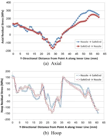
는 레이저 피닝 방향 변화에 따른 내표 Fig. 19
면 상의 잔류응력 분포 변화를 보여주고 있다.
은 레이저 피닝 방향 변화에 따른 내면 보 Fig. 20
수용접 중앙선 상의 잔류응력 분포 변화를 보여 주고 있다. Fig. 19와 20에서 보이는 바와 같이 레이저 피닝 방향의 영향은 미미함을 알 수 있 다.
4. 결 론
일체형 원자로 안전주입 노즐 이종금속 용접부 의 용접 잔류응력 이완에 대한 레이저 피닝의 효 과와 레이저 피닝 변수의 영향을 implicit 동적 유 한요소해석을 통해 고찰한 결과 다음과 같은 결, 론을 얻었다.
레이저 피닝은 주로 내표면 근처 영역의 잔 (1)
류응력만을 저감시키는 예방정비 효과가 있다.
최대 충격압력이 증가할수록 내표면에서의 (2)
이완효과는 증가하다가 감소하며 이완이 발생하 는 영역의 깊이는 증가한다.
충격압력 지속시간이 증가할수록 내표면에 (3)
서의 이완효과는 증가하며 이완이 발생하는 영역 의 깊이도 증가한다.
레이저 스폿 직경은 최대 충격 압력과 충격 (4)
압력 지속시간에 비해 상대적으로 미미한 영향을 준다.
레이저 피닝 방향이 잔류응력 이완정도에 (5)
미치는 영향은 미미하다.
참고문헌
(1) KINS, 2009, Development of Regulatory Assessment Technology for Small and Medium Power Reactors, KINS/HR-1050.
(2) Gorman, J., Hunt, S., Riccardella, P. and White, G.A., 2008, Chapter 44. PWR Reactor Vessel Alloy 600 Issues, Companion Guide to the ASME Boiler
& Pressure Vessel Code, Third Edition, Volume 1, ASME.
(3) KEPRI, 2007, Development of Material Degradation Evaluation System for Major Nuclear Components, Final Report.
(4) Wu, W.W. and Tsai, C.H., 1998, "Hot Cracking
Part 1: Alloy 82/182 Pipe Butt Welds, TR-1001491 (MRP-44).
(7) Gilles, P. and Cipiere, M.F., 2006, "Residual Stress Influence on Dissimilar Material Weld Junction Fracture," Fracture of Nano and Engineering Materials and Structures, Proceedings of the 16th European Conference of Fracture, Alexandroupolis, Greece.
(8) Anastasius, Y., 2006, Residual Stress and Its Effects on Fatigue and Fracture, Proceedings of a Special Symposium held within the 16th European Conference of Fracture - ECF16, Alexandroupolis, Greece, Springer.
(9) Kim, J.S., Jin, T.E., Dong, P. and Prager, M., 2003, "Development of Residual Stress Analysis Procedure for Fitness-For-Service Assessment of Welded Structure," Transactions of KSME A, Vol.27, No.5, pp.713~723.
(10) Kim, J.S. and Jin, T.E., 2007, "Development of Engineering Formulae for Welding Residual Stress Distributions of Dissimilar Welds on Nozzle in Nuclear Component," Proceedings of ASME 2007 PVP Conference, San Antonio, USA, PVP2007-26729.
(11) Song, T.K., et al., 2009, "Assessment of Round Robin Analysis Results on Welding Residual Stress Prediction in a Nuclear Power Plant Nozzle,"
Transactions of KSME A, Vol.33, No.1, pp.72~81.
(12) Nam, T.S., 2002, Finite Element Analysis of Residual Stress Field Induced by Laser Shock Peening, Dissertation Presented in Partial Fulfillment of the Requirements for the Degree Doctor of Philosophy in the Graduate School of the Ohio
Laser Peening," Welding International.
(15) Simulia, 2009, ABAQUS User’s Manuals, Ver.6.8.
(16) Ballard, P., 1991, Residual Stresses Induced by Rapid Impact - Applications of Laser Shoc- king, Doctorial Thesis, Ecole Polytechnique, France.
(17) ASME B&PV Code Committee, 2001, ASME B&PV Code, Sec.II, Part D.
(18) Lee, J., et al., 2007, “Mechanical Properties Evaluation in Inconel 82/182 Dissimilar Metal Welds,” Proceedings of SMiRT19.
(19) Battelle, 2002, Investigation of Weld Residual Stresses and Local Post-Weld Heat Treatment, Final PVRC JIP Report.
(20) EU JRC Institute for Energy, 2004, Protocol for Finite Element Simulations of the NET Single-Bead-on-Plate Test Specimen.
(21) Huntington Alloys. Inc., 1980, CMTR.
(22) Hans Nordberg, March 2004, Note on the Sensitivity of Stainless Steels tro Strain Rate, Avesta Polarit Research Foundation, Research Report, No 04-0-1.
(23) Davies, R.G. and Magee, C.L., 1977, “The Effect of Strain Rate Upon the Bending Behavior of Materials,” Trans. of ASME, J. of Engineering Materials and Technology, Vol. 99, pp.47~51.
(24) Ding, K. and Ye, L., 2006, Laser Shock Peening Performance and Process Simulation, Woodhead Publishing Limited.
(25) Singh, G., 2009, Effective Simulation and Optimization of Laser Peening Process, a Thesis of Doctor of Philosophy, Wright State University.