논문 2013-50-11-5
복합 좌우향 전송선로를 이용한 UWB 대역통과 필터의 설계
( Design of UWB Bandpass Filter using CRLH Transmission Line )
김 기 래**
( Girae Kim
ⓒ)
요 약
본 논문에서는 덤벨형 결함 접지면 구조를 갖는 복합 좌-우향(CRLH) 전송선로를 이용하여 초광대역 대역통과 여파기를 설 계하였다. 결함 접지면 구조와 마이크로스트립 인터디지털 캐패시터를 이용하여 CRLH 전송선로를 구현하고 이것을 이용하여 필터를 설계하였다. CRLH 전송선로는 저역통과와 고역통과 필터의 복합적인 특성을 나타내는데, 그것들의 차단주파수를 잘 조절함으로써 초광대역의 대역통과 필터의 특성을 얻을 수 있다. UWB 필터 특성을 얻기 위해 1, 2 ,4, 8 셀을 갖는 CRLH 전 송선로에 대해 시물레이션하였고, 본 논문에서는 결과를 검증하기 위해 4 셀 구조의 UWB 필터를 설계 제작하였다. 측정된 결 과는 시뮬레이션 결과와 일치하며 5GHz 중심주파수에서 88%의 넓은 대역폭을 갖는다.
Abstract
A novel design method of ultra wideband bandpass filter using CRLH transmission line with Dumbell type DGS is presented in this paper. Defected Ground Structure and microstrip interdigital capacitor are used to design the ultra wideband (UWB) filter. CRLH transmission line has composite characteristics of low pass and high pass filter. As control of cutoff frequency of low pass and high pass response on CRLH transmission line, we can get characteristic of UWB filter. We designed and simulated for CRLH transmission lines with one, two, four, and eight cells. A UWB filter using four cells CRLH is designed and fabricated to verify the results. The characteristics of designed filter have center frequency of 5GHz and relative bandwidth of 88%.
Keywords: Composite Right-Left Handed (CRLH) Traqnsmission Line, Defected Ground Structure (DGS), Ultra wideband (UWB) filter
Ⅰ. Introduction
Ultra Wide Band (UWB) technology has aroused significant interest of researchers since the U.S.
Federal Communications Commission (FCC) approved the unlicensed use of UWB (3.1∼10.6 GHz) for commercial communication purpose[1]. To date, numerous studies on planar filter technologies have been explored for UWB applications[2~3]. An example
* 평생회원, 신라대학교 전자공학과
(Dept. of Electronic Engineering, Silla University)
ⓒ Corresponding Author(E-mail: [email protected]) 접수일자: 2013년7월15일, 수정완료일: 2013년10월25일
of UWB bandpass filter using stub-loaded multi- mode resonator (MMR) is represented in [4]. A widened upper-stopband is realized by incorporating this MMR with two interdigital parallel-coupled feed lines. The insertion loss obtained is less than 0.8dB, and return loss higher than 14.3 dB with a fraction bandwidth of 114 %; however, its selectivity is rather poor. Recently, classic microwave bandpass filter theory has been well established in designing narrow and moderate bandwidth filters. But it is not suitable for designing filters with a large bandwidth. So, a great effort has been made in designing the ultra
wideband (UWB) bandpass filter with novel structures, and many methods are used to design the UWB bandpass filter[5~6]. In this paper, a novel kind of UWB bandpass filter is designed based on the composite right-/left handed (CRLH) transmission line[7], which has highpass property at lower frequencies and lowpass property at higher frequencies, thus constructs an UWB filter. Dulbell type defected ground structure and interdigital capacitor are introduced to satisfy the necessity of the filter. The proposed structure has good characteristics of low insertion loss, ultra wide passband, and improved selectivity characteristics. It has low insertion loss of 0.5dB, and fractional bandwidth of 98% at 5GHz center frequency. The structures with different cell number are studied, but a four cell CRLH UWB filter is fabricated and measured, which has good agreement between simulation and measurement results.
Ⅱ. CRLH Transmission Line
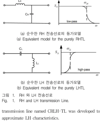
Metamaterial is an artificially engineered structure that gains its material properties from its structure as its intrinsic material composition[8,9]. For the purely right-handed (RH) transmission line as shown in Figure 1(a), it consists of series inductance and shunt capacitance and shows a lowpass response. In contrast, for the purely left-handed(LH) transmission line as shown in Figure 1(b), it consists series capacitance and shunt inductance and shows a highpass response. In lossless condition, we can get cutoff frequencies of RHTL and LHTL in equivalent circuit of Figure 1 as following (1) and (2).
(1)
(2)
The purely LH transmission line cannot be realized in the natural materials because of unavoidable parasitic RH effect; therefore an artificial
(a) 순수한 RH 전송선로의 등가모델 (a) Equivalent model for the purely RHTL
(b) 순수한 LH 전송선로의 등가모델 (b) Equivalent model for the purely LHTL 그림 1. RH 와 LH 전송선로
Fig. 1. RH and LH transmission Line.
transmission line named CRLH-TL was developed to approximate LH characteristics.
Figure 2 displays the infinitesimal equivalent circuit model of the CRLH-TL. The transmission line can be realized by cascading N unit cell with period of . The total length of the transmission line is N times
. Each unit cell in this periodic structure includes the series inductance (), series capacitance (), shunt capacitance () and shunt inductance () in this model.
The equivalent circuit of CRLH transmission line, which consist of a pure RHTL cascaded with a pure LHTL is shown in Figure 2. It takes on bandpass property under the balanced condition, where and
are the high-pass cutoff frequency of pure LHTL and the low- pass cutoff frequency of pure RHTL, respectively. The center frequency of the passband is as following (3).
(3)
Given the values of the CRLH structure has a bandpsass characteristic when
. For the requirements of UWB filter under the balanced condition, the key problem is to design
그림 2. CRLH 전송선로의 등가회로
Fig. 2. Infinitesimal equivalent circuit model of the CRLH-TL.
a CRLH transmission line with larger and smaller . Although the CRLH transmission line based on the equivalent LC circuit is a bandpass filter in nature the design method is completely different from that of conventional filter.
Ⅲ. Proposed UWB Filter
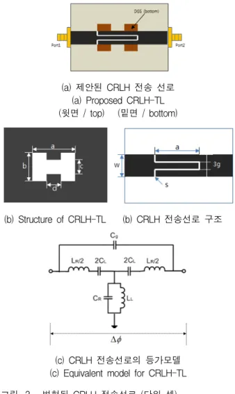
In this paper, The modified CRLH structure is described by the circuit model as shown in Figure 3.
The LH shunt inductance and series capacitor, the RH shunt capacitor and series inductance are similar to those of the conventional CRLH structure of Figure 2. An additional cross-coupled capacitance is introduced to created some novel characteristics.
In this paper, the series tank is realized with microstrip interdigital capacitor, and the shunt tank is implemented by dumbbell type defected ground structure.
In Figure 3, the interdigital capacitor was designed with the finger width g=0.6mm, spacing between adjacent fingers s=0.2mm, the finger length a=10mm, line width for 50ohm of w=2.3mm. The dumbell type DGS has length of a=10mm, width of b=2.7mm and gaps of c=2.3mm, d=4mm. The proposed band pass filter is simulated by full-wave EM simulator HFSS.
(a) 제안된 CRLH 전송 선로 (a) Proposed CRLH-TL (윗면 / top) (밑면 / bottom)
(b) Structure of CRLH-TL (b) CRLH 전송선로 구조
(c) CRLH 전송선로의 등가모델 (c) Equivalent model for CRLH-TL 그림 3. 변형된 CRLH 전송선로 (단위 셀) Fig. 3. Modified CRLH Transmission Line.
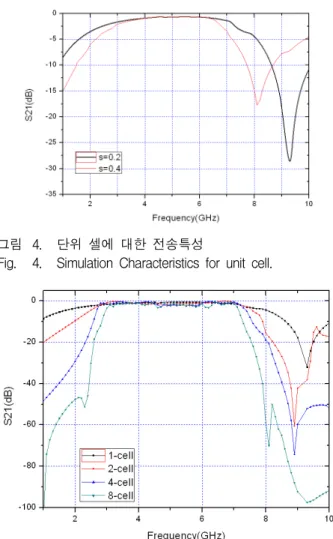
The S21 characteristics for proposed CRLH transmission line of Figure 3 are shown in Figure 4.
The S21 characteristics are compared when spacing between adjacent fingers is s=0.2mm and s=0.4mm.
When the spacing between adjacent fingers (s) is 0.2mm as shown in Figure 4, bandwidth of filter is from 2.2GHz to 7.5GHz. The interdigital capacitor has a relatively larger value of series capacitor while DGS in ground plane will decrease the shunt capacitor , which may satisfy the ultra wideband condition ≪ . The other parameters are carefully selected to meet balanced CRLH requirement, which avoids the bandgap in the wide pass-band range. We used the board for microstrip line with a dielectric constant of and a
그림 4. 단위 셀에 대한 전송특성
Fig. 4. Simulation Characteristics for unit cell.
그림 5. 셀수에 따른 필터의 시뮬레이션 결과 Fig. 5. Simulation Results of UWB filter.
thickness of 1mm. The unit cell as well as the periodic structure is studied. Each cell structure is composed of an interdigital capacitor with a defected aperture on ground plane. The interdigital capacitor was designed with the finger width g=0.6mm, spacing between adjacent fingers s=0.25mm, the finger length a=10mm, line width for 50ohm of w=2.3mm, pitch of each cell p=9.5mm, and the number of fingers N=3. The dumbell type DGS has length of a=10mm, width of b=2.7mm and gaps of c=2.3mm, d=4mm. Simulated frequency response of one-cell, two-cell, four-cell, and 8-cell CRLH structures are compared in Figure 5, which shows an obvious UWB bandpass response with a wide passband range 2.8 to 7.2GHz and a low insertion loss of less than 0.5dB. The relative bandwidth is
about 88%. The out-of-band suppression of the UWB filter gets better as the cell number increases.
Ⅳ. EXPERIMENT RESULTS
To validate the theory, four cell CRLH structure was fabricated and measured with Agilent Vector Network Analyzer. Figure 6(a) and 7(b) are configurations of top and bottom side of four cells
(a) 마이크로스트립 인터디지털 캐패시터 (윗면) (a) Microstrip interdigital capacitor (top side)
(b) 결함 접지면 구조 (밑면) (b) Defected ground structure (bottom side) 그림 6. 제안하는 UWB 필터 구조
Fig. 6. The proposed structure for UWB filter.
(a) 윗면 사진 (Top view)
(b) 밑면 사진 (Bottom view) 그림 7. 제작된 4-셀 구조의 UWB 필터 Fig. 7. Fabricated four-cell UWB filter.
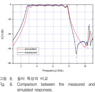
그림 8. 필터 특성의 비교
Fig. 8. Comparison between the measured and simulated responses.
filter, and Figure 7(a) and 7(b) are photos of top and bottom side of four cells CRLH UWB filter, respectively. The comparison of simulation and measurement results are shown in Figure 8.
V. CONCLUSION
The novel design method of UWB bandpass filter using the composite right-/left handed (CRLH) transmission line is represented in this paper. The DGS and interdigital capacitor are used to construct the basic CRLH structure. The proposed structure has good characteristics of low insertion loss and ultra wide passband. It has low insertion loss of 0.5dB, and fractional bandwidth of 88% at 5GHz center frequency. The structures with different cell number are studied, but a four cell CRLH UWB filter is fabricated and measured, which has good agreement between simulation and measurement results.
REFERENCES
[1] Federal Communications Commission (FCC), Revision of Part 15 of the Commission’s Rules Regarding Ultra-Wideband Transmission Systems, First Report and Order, FCC 02-48, 2002.
[2] H.L. Hu, X.D. Huang, and C.H. Cheng,
“Ultra-wideband bandpass filter using CPW-to -microstrip coupling structure, “Electron Lett.
42, 2006.
[3] T.N. Kuo, S.C. Lin, and C.H. Chen, “Compact Ultra-wideband bandpass filters using composite microstrip coplanar waveguide structure, IEEE
Trans on Micrrowave Theory Tech. MTT-54
pp. 3772-3778, 2006.[4] R. Li and L. Zhu, “Compact UWB bandpass filter using stub-loaded multiple-mode resonator,” IEEE Microwave Wireless Compon.
Lett., Vol.16, no.8, pp.440-442, Aug. 2006.
[5] Singh, P.K.,Sarbani, and Y. Wang,“Planar ultra- wideband bandpass filter using edge coupled microstrip lines and stepped impedence open stub,” IEEE Microwave Wireless Compon. Lett., Vol. 17, 649-651, 2007.
[6] Menzel, W. and P. Feil, “Ultra-wideband (UWB) filter with WLAN notch,” Proc. 36th EUMC, 595-598, 2006.
[7] V. G. Veselago, “The electrodynamics of substances with simulataneously negative values of ε and μ ”, Sov. Phys. Usp., vol.10, pp. 509, Jan.1968.
[8] O. F. Siddiqui, M. Mojahedi, and G. V.
Eleftheriades, “Periodically loaded transmission line with effective negative refractive index and negative group velocity,” IEEE Trans. Antennas
Propag., vol. 51, no. 10, pp. 2619-2625, Oct.
2003.
[9] A. A. Oliner, “A periodic-structure negative- refractive index medium without resonant elements,” in Proc. USNC/URSI Nat. Radio Sci.
Meeting, pp. 41, San Antonio, TX, 2002.
저 자 소 개 김 기 래(평생회원)
1986년 서강대학교 전자공학과 학사 졸업 (공학사) 1988년 서강대학교 전자공학과 석사 졸업 (공학석사) 1998년 경남대학교 전자공학과 박사 졸업 (공학박사) 1988∼1993년 삼성전자(주) 정보통신연구소 1993∼1999년 마산대학교 정보통신공학과 조교수 1999∼현재 신라대학교 전자공학과 교수
<주관심분야 : 무선통신시스템, 초고주파 회로설 계, 레이더 시스템, 전자파 흡수체>