CopyrightⒸ2012 KSAE / 117-05 pISSN 1225-6382 / eISSN 2234-0149 DOI http://dx.doi.org/10.7467/KSAE.2012.20.3.026
Transactions of KSAE, Vol. 20, No. 3, pp.26-36 (2012)
대형 2행정 디젤기관용 축압분배기 부착 전자제어식 퀼 시스템 모터구동 실린더 주유기의 주유 불균일률에 관한 연구
배 명 환*1)․정 화2)․배 창 환3)
경상대학교 기계공학부1)․경상대학교 대학원 기계설계학과2)․호서대학교 BK21사업단 융합대학원3)
A Study on Inequality Rate of Lubrication for Motor-driven Cylinder Lubricator by the Electronically Controlled Quill System Equipped with an Accumulating Distributor in a Large Two-stroke Diesel Engine
Myung-whan Bae*1)․Hwa Jung2)․Chang Hwan Bae3)
1)
School of Mechanical Engineering, Gyeongsang National University, Gyeongnam 660-701, Korea
2)
Department of Mechanical Engineering for Production, Graduate School, Gyeongsang National University, Gyeongnam 660-701, Korea
3)
Graduate School of Convergence Technology, BK21 Project, Hoseo University, Chungnam 336-795, Korea
(Received 27 September 2011 / Revised 4 November 2011 / Accepted 12 December 2011)Abstract : Minimizing the cylinder wear and the consumption rate of cylinder oil in a large two-stroke diesel engine is of great economic importance. A motor-driven cylinder lubricator for Sulzer RT-flex large two-stroke diesel engines developed by authors is in need of mounting a quill system to lubricate cylinder parts for a smooth operation. In order to apply the common-rail lubricating system to the developed cylinder lubricator as the second research stage, the mechanical quill system with a progressively quantitative distributor (M.D.S.) is improved in the electronically controlled quill system with an accumulating distributor (E.D.S.). In this study, the effects of lubricator motor speed, plunger stroke and cylinder back pressure on oil feed rate and inequality rate are experimentally investigated by applying E.D.S. to the developed cylinder lubricator. It is found that the oil feed rate of E.D.S. is higher than that of M.D.S.
because of the increase of delivery speed and volume by changing the role of accumulator in the same experimental condition. It can be also shown that, in E.D.S., the inequality rate is decreased a little or hardly unchanged as the cylinder back pressure and plunger stroke is elevated, while the inequality rate increased in M.D.S.. The inequality rates of E.D.S.
and M.D.S. are lowered as the lubricator motor speed is increased.
Key words : Cylinder lubricator(실린더 주유기), Electronically controlled quill system equipped with an accumulating distributor(축압분배기 부착 전자제어식 퀼 시스템), Inequality rate of lubrication(주유 불균일 률), Large two-stroke diesel engine(대형 2행정 디젤기관), Oil feed rate(송출유량)
1)1. 서 론
최근 중국, 인도 등의 급속한 경제성장과 유가의 불안정한 급등은 미래 경제전망의 예측을 불가능하
* Corresponding author. E-mail: [email protected]
게 하고 있다. 이러한 가운데에서도 한국의 조선업 계는 최근 몇 년간 호황세가 지속되고는 있지만, 2007년도 초반에는 시기에 따라 중국의 조선업계에 의해 수주량이 추월당하는 상황에 달해 언제까지 세 계 1위의 자리에 안주해 있을지가 불안한 상태이다.
따라서 한국의 조선업계는 이제 단순 노동집약산업
대형 2행정 디젤기관용 축압분배기 부착 전자제어식 퀼 시스템 모터구동 실린더 주유기의 주유 불균일률에 관한 연구
의 단계를 벗어나 기술집약적인 산업구조로 변모되 어야 수주량, 건조량 및 잔량을 포함한 조선강국을 지속적으로 유지할 수 있을 것이다.
최근, 대형 2행정 디젤기관의 부품개발에도 전자 제어 기술의 발달과 환경규제 강화 추세에 따라 이 들에 대한 적용이 많이 이루어지고 있다. 특히 저속 디젤기관의 시장은 기관의 기동특성에 맞게 커먼레 일 방식을 적용하여 연료를 분사하고, 실린더유 주 유시점을 조정함으로써 연료 소모량과 배출가스를 줄여 최적의 운전조건을 제공할 수 있는 전자제어 기관의 출시를 가속화하여 왔다. 그 결과, 전자제어 기관의 수요는 점차 증가하는 추세이고, 전자제어 기관 핵심부품의 가격 비중이 상대적으로 많은 부분 을 차지하고 있기 때문에, 수입의존도가 높아 국산 화 개발의 중요성이 더욱 커지고 있다.
한편, 장행정화에 의해 고출력 및 고효율을 도모 하면, 열효율을 이론값에 근접시킬 수 있기 때문에, 더 이상 연료소비율 개선의 여지는 거의 없지만, 실 린더와 피스톤 링의 접동거리가 늘어나 양호한 윤활 상태를 유지시키는 것이 어렵게 된다. 따라서 운전 비용을 절감시키기 위해서는 연료에 비해 단가가 높은 실린더 윤활유의 저감대책이 중요하게 되는데, Baba 등1)은 주유량 저감에 의해 운전비용을 대폭적 으로 절감시킬 수 있음을 보고하였다.
그러나 기존 실린더 주유기를 사용해서는 적정한 윤활상태에서 주유량을 저감시키기 어렵기 때문에, 최근 고속고압 주유방식과 SIP(Swirl Injection Principle) 주유방식이 개발되어 다양한 시험을 통해 실린더 주유량을 감소시킬 수 있다고 하는 실적 데 이터가 발표되었다.2~4)
저자들은 독자적인 기술로 개발한 실린더 주유기 를 사용하여 모형 실린더에 실제 적용되는 분배기를 설치하고 끝단의 퀼을 전자제어에 의해 조절할 수 있도록 솔레노이드 밸브를 장착시켜 주유하였을 경 우5)와 연료분사에 적용하고 있는 커먼레일 시스템 을 윤활유 주유에도 적용하기 위해 퀼 구조를 단순 화시켜 제작한 개량 전자제어 퀼을 사용하여 주유하 였을 경우6)에 대해 실린더 주유기 특성을 조사하여 성능에 미치는 영향을 파악해 보았다. 그런데 기존 의 기계식 분배기는 정량식 순차적으로 분배가 이루
어지지만, 본 연구와 같은 전자제어 퀼 시스템의 경 우에는 순차적이 아니고 규정압력 이상이 되면 자동 적으로 윤활유가 분배되는 시스템이다.
본 연구에서는 실린더 주유기에 커먼레일 시스템 을 적용시키기 위한 2단계로서 실린더 주유기의 성 능에 미치는 영향을 파악하기 위해, 실제기관의 분 위기에 맞도록 질소가스를 사용하여 모형 실린더 내 의 압력을 일정하게 형성시키고, 주유기 회전속도와 플런저 행정을 파라미터로 하여 모형 실린더와의 사 이에 축압분배기를 설치한 다음, 전자제어 퀼을 장 착시켜 솔레노이드 밸브에 의해 윤활유를 주유시킨 다. 4개의 실린더에 주유된 송출유량을 각각 측정하 고, 기존 정량분배기 기계식 퀼 시스템과 축압분배 기 부착 전자제어식 퀼 시스템에 대한 실린더 주유 기의 주유 불균일률을 각 실린더별로 조사하여 비교 하는 것이 목적이다.
2. 실험 장치 및 방법
2.1 실험장치
Fig. 1에는 축압분배기 부착 전자제어식 퀼 시스 템에 의해 실린더 주유기에 배압을 걸어 준 상태에 서 주유기 본체의 성능을 시험하기 위하여 구성한 실험장치의 개략도를 보여주고, Table 1에는 실린더 주유기의 주요 제원을 나타내고 있다.
질소가스에 의해 배압이 형성되도록 외경 100
Fig. 1 Schematic diagram of experimental apparatus
Myung-whan Bae․Hwa Jung․Chang Hwan Bae
Table 1 Specifications of test cylinder lubricator
Item Specification
Type RTA48T
Plunger diameter (mm) 12
Stroke (mm) 9
Discharge quantity
(cc/(point․stroke)) 2.03
mm, 높이 50 mm, 두께 25 mm의 모형 실린더가 설치 되어 있는데, 내부의 주유 모습을 관찰할 수 있도록 아크릴로 제작하였다. 또한, 주유기 출구로부터 관 길이 5 m 지점에 축압분배기를 설치하였고, 6.78 m 지점의 끝단에는 전자제어에 의해 작동되는 솔레노 이드 밸브를 대형 2행정 디젤기관용 실제 퀼에 부착 시켜 윤활유가 유효한 기간 내에 분사될 수 있도록 하였다.(이하 축압분배기 부착 전자제어식 퀼 시스 템(Electronically Controlled Quill System with an Accumulating Distributor ; E.D.S.)이라고 칭한다.)7) 한편, 정량적 순차방식의 분배기를 사용한 기계식 퀼에 의해 분사했을 경우를 정량분배기 기계식 퀼 시스템(Mechanical Quill System with a Progressively Quantitative Distributor ; M.D.S.)이라고 칭하여 축압 분배기 부착 전자제어식 퀼 시스템의 주유 불균일률 과 비교하였다.
전자제어 시스템은 전원이 DC 12 V이고, 주유구 끝단에서 0.03 m 떨어진 지점에 설치한 압전식 압력 계에서 측정된 압력이 규정압력 이상일 경우에 제어 시스템은 퀼에 부착된 솔레노이드 밸브에 DC 12 V 가 공급된다. 이 때 규정전압은 전자제어 시스템에 설치된 선택스위치에 의해 조절할 수 있다.
기존 정량분배기 기계식 퀼 시스템의 경우에는 주 유기에서 분배기로 공급되는 오일은 순차적 정량방 식 분배기(Lubriquip, 4 section divider)에 의해 4개의 유관으로 오일이 공급된다. 기존 퀼에는 실린더, 압 축 스프링, 피스톤 및 다이어프램으로 구성된 어큐 뮬레이터가 내부에 설치되어 있다.8)
본 연구의 축압분배기 부착 전자제어식 퀼 시스템 은 기존 정량분배기 기계식 퀼 시스템의 각 퀼 내에 설치되어 있는 어큐뮬레이터를 하나의 축압분배기 내에 설치하고, 축압분배기 내에 오일 압력조절기를
Fig. 2 Accumulated distributor
장착하여 40 bar 이상 압력에서 작동할 수 있도록 체 크밸브(nonreturn valve)를 설정하여 과도하게 상승 된 압력으로 주유되는 것을 방지하였다. Fig. 2는 실 험에 사용한 축압분배기를 보여주고 있는데, 피스 톤은 직경 25 mm, 행정 20 mm로서 20 bar 이상의 압 력에서 작동하도록 스프링 탄성계수를 설정하였다.
윤활유는 주유기로 유입되기 전 오일탱크에 저장 하였고, 코일식 전기히터(3 kW × 2 대)의 가열에 의 해 윤활유 온도를 본 실험에서 사용한 45℃까지 증 가시켰다. 유압펌프에 의해 가열된 윤활유가 주유기 내 저장탱크 안으로 유입되고, 온도센서가 부착된 온도조절기를 탱크 내에 설치하여 자동적으로 설정 온도를 조절하였다.
주유기 내에 코일식 전기히터(75 W)와 자동 온도 조절기를 설치하여 오일탱크와 주유기 사이의 관을 통과하는 시간, 주유기내로 유입되어 체류하는 시 간, 주유구를 통하여 주유관을 통과하는 시간 동안 에 발생되는 온도 변화를 작게 하였고, 설정온도가 유지되도록 하였다. 또한, 관 전체를 보온재로 감싸 서 가능한 온도차를 줄이도록 하였다.
주유기 축에 설치된 광센서를 이용한 레이저 회전 속도 측정기(Pocket tachometer TESTO 465)에 의해 주유기 본체인 플런저 펌프 회전속도를 측정하였고, 회전속도는 모터 축에 연결된 인버터(KC-1500A) 주 파수에 의해 바꿀 수 있도록 했다.
1기의 실린더는 상단 및 하단에서 주유하기 때문 에, 4 실린더용 주유기의 경우에는 주유구가 전체 8 개인데, 동일한 실험조건에서는 각 주유구의 토출량 이 같다고 가정하여 1번 주유구의 성능만을 측정했 고, 나머지 주유구의 토출량은 탱크로 반송되도록 관을 설치하였다. 압전식 압력계를 설치하여 1번 주
A Study on Inequality Rate of Lubrication for Motor-driven Cylinder Lubricator by the Electronically Controlled Quill System Equipped with an Accumulating Distributor in a Large Two-stroke Diesel Engine
유구의 끝단에서 0.03 m 떨어진 위치의 토출압력, 퀼 에서 분사되기 직전 주유관 끝단의 송출압력 및 질 소 탱크로부터 모형실린더 내로 주입되기 전의 배압 형성용 질소가스 압력을 각각 측정하였다.
퀼에서 2.5 m 떨어진 지점의 유관에 타이머가 부 착된 솔레노이드 밸브(KSO-G-2B)를 설치하여 유량 측정시간을 제어하였다. 주유관은 내경 6 mm인 스 테인리스 강관을 사용했다.
2.2 실험방법
Table 2에는 측정항목에 따른 실험조건을 나타내 고 있다. 실제 운전 중인 디젤기관과 유사한 환경을 설정하기 위해 본 실험에서는 오일온도를 45℃로 가 열하여 사용하였다. 주유기 모터의 회전속도는 60, 80, 100 및 120 rpm로 변화시켰고, 플런저 행정은 9 mm이지만, 2 mm에서 8 mm까지 2 mm씩 증가시켰 다. 이전 연구9)에 의하면 주유관 길이는 주유기 성능 에 거의 영향을 미치지 않았기 때문에, 본 연구에서 는 주유관 길이를 이전 연구10~12)와 동일한 6.78 m로 하였다.
실험에서 모형 실린더 내의 배압은 6, 11 및 16 bar 로 하였는데, 실제 대형 2행정 디젤기관은 실린더 내 에서 공기를 압축하는 과정 중인 10 ~ 20 bar일 때 주 유기로부터 실린더 오일이 주유된다. 따라서 주유기 에서 분출되는 압력이 실린더내의 압력보다 높을 때 에만 실린더 오일이 분사되어 윤활유로서의 역할을 할 수 있다. 본 연구에서 6 bar는 실린더 오일이 분사 될 때의 실린더 내 압력범위는 아니지만, 비교하기 위해 실험조건으로 추가하였다. 주유구 끝단에서 0.03 m 떨어진 지점에 설치한 압전식 압력계에서 측 정된 압력이 설정한 배압 이상일 경우에 전자제어 시스템은 퀼에 부착된 솔레노이드 밸브에 DC 12 V 의 전원이 공급되어 작동하게 된다. 이 때 설정된 배 압에 해당되는 규정전압은 선택스위치에 의해 0.5 V (6 bar), 1.0 V(11 bar), 1.5 V(16 bar)로 조절할 수 있다.
각 실험조건에서 측정된 압력파형을 디지털 스토 레지 오실로스코프(Yokogawa DL9240, 8 bits, 2.5 MW/CH)에 저장하고, 저장된 압력파형에서 최대 토 출 및 송출 압력을 구하였다.
타이머 부착 솔레노이드 밸브를 이용하여 120초
Table 2 Experimental conditions and measuring items Plunger stroke (mm) 2, 4, 6, 8 Pump motor speed (rpm) 60, 80, 100, 120
Back pressure (bar) and
Control pressure of quill (bar) 6, 11, 16
Oil pipe length (m) 6.78
Measured spot of maximum
discharge pressure (m) 0.03
동안의 유량을 전자저울(Precisa XT 1220M, 최소 측 정단위 0.001 g)로 계량하여 송출유량을 단위시간당 질량값으로 나타내었는데, 송출유량은 각 실험조건 에 대해 5회 측정하여 최대 및 최소값은 버리고 나머 지 3회 측정값의 평균을 취하였다.
실험에 사용된 실린더 오일은 Mobil Gard 570으로 주요한 물리적 및 화학적 특성은 저자들의 논문5)을 참고하기 바란다. 본 연구의 실험에 있어서 주유기 회전속도의 변동률은 1 rpm 미만이었고, 실린더의 오일온도 변동률은 2℃ 미만이었다.
3. 실험 결과 및 고찰
3.1 송출유량
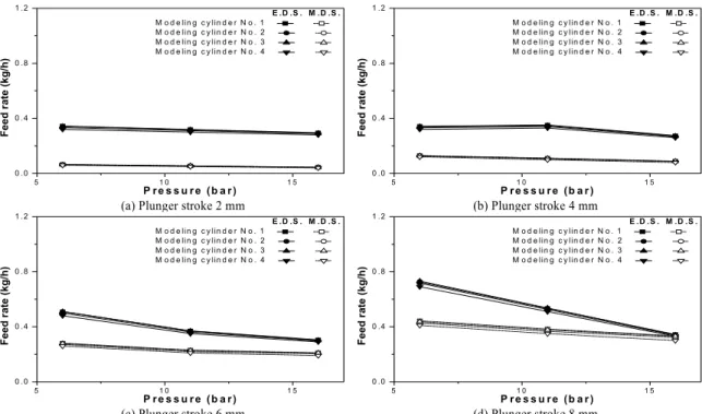
Figs. 3 ~ 6은 실린더 주유기 회전속도 60, 80, 100 및 120 rpm일 경우, 오일온도 45℃에서 플런저 행정 에 대한 각 실린더를 파라미터로 하여 모델링 실린 더 배압에 따른 정량분배기 기계식 퀼 시스템 (M.D.S.)과 축압 분배기 부착 전자제어 퀼 시스템 (E.D.S.)의 송출유량 값을 비교하여 나타내고 있다.
그림으로부터 M.D.S.와 E.D.S.에 관계없이 플런 저 행정과 주유기 회전속도가 증가할수록 송출유량 은 증가하였지만, 실린더 배압의 증가에 따라서는 송출유량이 감소하였다.
본 송출유량 값에 있어서 M.D.S. 및 E.D.S. 모든 경 우에 플런저 행정이 증가할수록 각 실린더 배압에 따른 4개 실린더의 송출유량이 불균일하여 값이 일 정하지는 않았고, 배압에 따른 영향은 M.D.S.의 경 우에 배압이 높을수록, E.D.S.의 경우에 배압이 낮을 수록 송출유량 값의 차이가 약간 발생함을 알 수 있 는데, 이것은 플런저 행정이 증가할수록 변화가 더 큼을 알 수 있었다. 한편, 본 연구에서는 E.D.S.가
배명환․정 화․배창환
5 1 0 1 5
0 .0 0 .4 0 .8 1 .2
Feed rate (kg/h)
P r e s s u r e (b a r )
E .D .S . M .D .S . M o d e lin g c y lin d e r N o . 1 M o d e lin g c y lin d e r N o . 2 M o d e lin g c y lin d e r N o . 3 M o d e lin g c y lin d e r N o . 4
5 1 0 1 5
0 .0 0 .4 0 .8 1 .2
Feed rate (kg/h)
P r e s s u r e (b a r )
E .D .S . M .D .S . M o d e lin g c y lin d e r N o . 1 M o d e lin g c y lin d e r N o . 2 M o d e lin g c y lin d e r N o . 3 M o d e lin g c y lin d e r N o . 4
(a) Plunger stroke 2 mm (b) Plunger stroke 4 mm
5 1 0 1 5
0 .0 0 .4 0 .8 1 .2
Feed rate (kg/h)
P r e s s u r e (b a r )
E .D .S . M .D .S . M o d e lin g c y lin d e r N o . 1 M o d e lin g c y lin d e r N o . 2 M o d e lin g c y lin d e r N o . 3 M o d e lin g c y lin d e r N o . 4
5 1 0 1 5
0 .0 0 .4 0 .8 1 .2
Feed rate (kg/h)
P r e s s u r e (b a r )
E .D .S . M .D .S . M o d e lin g c y lin d e r N o . 1 M o d e lin g c y lin d e r N o . 2 M o d e lin g c y lin d e r N o . 3 M o d e lin g c y lin d e r N o . 4
(c) Plunger stroke 6 mm (d) Plunger stroke 8 mm
Fig. 3 Comparison of feed rate relative to back pressure between the electronically controlled quill system equipped with an accumulating distributor and the mechanical quill system with a progressively quantitative distributor for four kinds of plunger stroke as a parameter of the respective modeling cylinder at a 120 rpm of cylinder lubricator speed(oil pipe length
= 6.78 m, oil temperature = 45℃)
5 1 0 1 5
0 .0 0 .4 0 .8 1 .2
Feed rate (kg/h)
P r e s s u r e (b a r )
E .D .S . M .D .S . M o d e lin g c y lin d e r N o . 1 M o d e lin g c y lin d e r N o . 2 M o d e lin g c y lin d e r N o . 3 M o d e lin g c y lin d e r N o . 4
5 1 0 1 5
0 .0 0 .4 0 .8 1 .2
Feed rate (kg/h)
P r e s s u r e (b a r )
E .D .S . M .D .S . M o d e lin g c y lin d e r N o . 1 M o d e lin g c y lin d e r N o . 2 M o d e lin g c y lin d e r N o . 3 M o d e lin g c y lin d e r N o . 4
(a) Plunger stroke 2 mm (b) Plunger stroke 4 mm
5 1 0 1 5
0 .0 0 .4 0 .8 1 .2
Feed rate (kg/h)
P r e s s u r e (b a r )
E .D .S . M .D .S . M o d e lin g c y lin d e r N o . 1 M o d e lin g c y lin d e r N o . 2 M o d e lin g c y lin d e r N o . 3 M o d e lin g c y lin d e r N o . 4
5 1 0 1 5
0 .0 0 .4 0 .8 1 .2
Feed rate (kg/h)
P r e s s u r e (b a r )
E .D .S . M .D .S . M o d e lin g c y lin d e r N o . 1 M o d e lin g c y lin d e r N o . 2 M o d e lin g c y lin d e r N o . 3 M o d e lin g c y lin d e r N o . 4
(c) Plunger stroke 6 mm (d) Plunger stroke 8 mm
Fig. 4 Comparison of feed rate relative to back pressure between the electronically controlled quill system equipped with an accumulating distributor and the mechanical quill system with a progressively quantitative distributor for four kinds of plunger stroke as a parameter of the respective modeling cylinder at a 100 rpm of cylinder lubricator speed(oil pipe length
= 6.78 m, oil temperature = 45℃)
대형 2행정 디젤기관용 축압분배기 부착 전자제어식 퀼 시스템 모터구동 실린더 주유기의 주유 불균일률에 관한 연구
5 1 0 1 5
0 .0 0 .4 0 .8 1 .2
Feed rate (kg/h)
P r e s s u r e (b a r )
E .D .S . M .D .S . M o d e lin g c y lin d e r N o . 1 M o d e lin g c y lin d e r N o . 2 M o d e lin g c y lin d e r N o . 3 M o d e lin g c y lin d e r N o . 4
5 1 0 1 5
0 .0 0 .4 0 .8 1 .2
Feed rate (kg/h)
P r e s s u r e (b a r )
E .D .S . M .D .S . M o d e lin g c y lin d e r N o . 1 M o d e lin g c y lin d e r N o . 2 M o d e lin g c y lin d e r N o . 3 M o d e lin g c y lin d e r N o . 4
(a) Plunger stroke 2 mm (b) Plunger stroke 4 mm
5 1 0 1 5
0 .0 0 .4 0 .8 1 .2
Feed rate (kg/h)
P r e s s u r e (b a r )
E .D .S . M .D .S . M o d e lin g c y lin d e r N o . 1 M o d e lin g c y lin d e r N o . 2 M o d e lin g c y lin d e r N o . 3 M o d e lin g c y lin d e r N o . 4
5 1 0 1 5
0 .0 0 .4 0 .8 1 .2
Feed rate (kg/h)
P r e s s u r e (b a r )
E .D .S . M .D .S . M o d e lin g c y lin d e r N o . 1 M o d e lin g c y lin d e r N o . 2 M o d e lin g c y lin d e r N o . 3 M o d e lin g c y lin d e r N o . 4
(c) Plunger stroke 6 mm (d) Plunger stroke 8 mm
Fig. 5 Comparison of feed rate relative to back pressure between the electronically controlled quill system equipped with an accumulating distributor and the mechanical quill system with a progressively quantitative distributor for four kinds of plunger stroke as a parameter of the respective modeling cylinder at an 80 rpm of cylinder lubricator speed(oil pipe length
= 6.78 m, oil temperature = 45℃)
5 1 0 1 5
0 .0 0 .4 0 .8 1 .2
Feed rate (kg/h)
P r e s s u r e (b a r )
E .D .S . M .D .S . M o d e lin g c y lin d e r N o . 1 M o d e lin g c y lin d e r N o . 2 M o d e lin g c y lin d e r N o . 3 M o d e lin g c y lin d e r N o . 4
5 1 0 1 5
0 .0 0 .4 0 .8 1 .2
Feed rate (kg/h)
P r e s s u r e (b a r )
E .D .S . M .D .S . M o d e lin g c y lin d e r N o . 1 M o d e lin g c y lin d e r N o . 2 M o d e lin g c y lin d e r N o . 3 M o d e lin g c y lin d e r N o . 4
(a) Plunger stroke 2 mm (b) Plunger stroke 4 mm
5 1 0 1 5
0 .0 0 .4 0 .8 1 .2
Feed rate (kg/h)
P r e s s u r e (b a r )
E .D .S . M .D .S . M o d e lin g c y lin d e r N o . 1 M o d e lin g c y lin d e r N o . 2 M o d e lin g c y lin d e r N o . 3 M o d e lin g c y lin d e r N o . 4
5 1 0 1 5
0 .0 0 .4 0 .8 1 .2
Feed rate (kg/h)
P r e s s u r e (b a r )
E .D .S . M .D .S . M o d e lin g c y lin d e r N o . 1 M o d e lin g c y lin d e r N o . 2 M o d e lin g c y lin d e r N o . 3 M o d e lin g c y lin d e r N o . 4
(c) Plunger stroke 6 mm (d) Plunger stroke 8 mm
Fig. 6 Comparison of feed rate relative to back pressure between the electronically controlled quill system equipped with an accumulating distributor and the mechanical quill system with a progressively quantitative distributor for four kinds of plunger stroke as a parameter of the respective modeling cylinder at a 60 rpm of cylinder lubricator speed(oil pipe length = 6.78 m, oil temperature = 45℃)
Myung-whan Bae․Hwa Jung․Chang Hwan Bae
M.D.S.보다도 동일한 실험조건에서 어느 경우에서 나 송출유량이 많이 나타났다.
그림에서 플런저 행정이 커질수록 송출유량이 증 가하는 것은 송출체적이 증가되기 때문이고, 실린더 배압이 증가할수록 송출유량이 감소하는 것은 송출 속도가 떨어지고, 주유기간이 상대적으로 짧아지기 때문이다.6) 또한, 주유기 회전속도가 빨라지면 송출 속도가 커지므로 송출유량은 증가한다.
본 연구에서 E.D.S.의 경우에는 퀼 내부의 심압봉 을 제거한 상태인 φ 7 mm의 관에서 실린더 오일을 주유하고, M.D.S.의 경우에는 어큐뮬레이터의 역할 을 살리기 위해 내부에 φ 6 mm의 심압봉을 삽입하 였기 때문에 실제로 실린더 오일이 양쪽 0.5 mm 간 격의 관사이로 통과하게 된다. 따라서 M.D.S.의 경 우에 점성이 큰 실린더 오일은 접촉면적이 2배 정도 크기 때문에 점성저항이 커져서 송출속도가 작아지 고, 송출체적도 작아져 송출유량이 감소된다. 이러 한 이유 때문에, Figs. 3 ~ 6에서 M.D.S.보다 E.D.S.의 송출유량이 더 많이 나타났다.
한편, 기계식의 각 퀼 내에 축압 기능을 갖는 어큐 뮬레이터를 E.D.S.의 경우에는 축압분배기 내부의 피스톤 방식으로 설계하고 제작하여 설치했는데, 이 방식은 기계식의 복잡한 퀼 내부를 단순화시켜 점성 저항을 감소시킬 수 있었다. 이 경우, 축압분배기 내 에 압력조절기를 설치하여 설정압력인 40 bar 이상 이 되면 유입된 오일이 오일탱크로 피드백되어 과도 한 주유를 방지할 수 있도록 하였다.
3.2 주유 불균일률
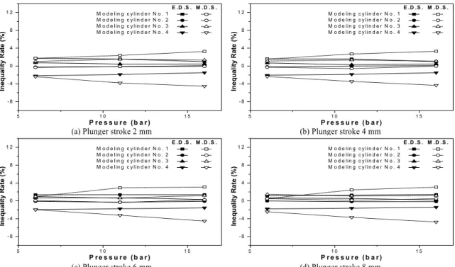
Figs. 7 ~ 10에서는 Figs. 3 ~ 6에서 측정한 각 모델 링 실린더에 대한 송출유량의 편차를 파악하기 위해 축압분배기 부착 전자제어식 퀼 시스템과 정량분배 기 기계식 퀼 시스템의 주유 불균일률을 비교하여 나타내고 있다. 여기서 주유 불균일률은 축압분배기 의 각 분배구에서 각 실린더로 토출되는 송출유량의 균일성을 알아보기 위한 척도로서, 4개 실린더의 주 유량 평균값을 기준으로 하여 각 실린더의 송출유량 과의 차로서 정의를 내려 다음과 같이 산출하였다.
주유 불균일률 평균 송출유량
송출유량 평균 송출유량
×
Fig. 7은 주유기 회전속도가 120 rpm일 때 4개의 모델링 실린더에 대한 주유 불균일률을 나타낸 것으 로 실린더 배압 및 플런저 행정의 증가에 따른 E.D.S.
와 M.D.S.의 주유 불균일률의 변화가 크지 않음을 보여주고 있다. 그림에서 E.D.S.의 경우에는 주유 불 균일률의 범위가 -1.67 ~ 1.33%이고, M.D.S.는 -2.91
~ 2.44%로, E.D.S.에 비해 M.D.S.의 주유 불균일률이 더 높게 나타남을 알 수 있다.
Figs. 8, 9 및 10은 실린더 주유기 회전속도 60, 80 및 100 rpm일 경우의 실린더 배압에 따른 각 실린더 의 주유 불균일률을 보여준 것으로, 100 rpm에서 E.D.S.의 주유 불균일률은 -2.50 ~ 1.97%, M.D.S.의 주유 불균일률은 -4.74 ~ 3.31%이고, 80 rpm에서 E.D.S.의 주유 불균일률은 -4.4 ~ 2.77%, M.D.S.의 경 우는 -6.98 ~ 4.19%이며, 60 rpm에서 E.D.S.의 주유 불균일률은 -5.82 ~ 3.81%, M.D.S.는 -7.83 ~ 5.99%로 나타났다.
Figs. 7 ~ 10에서는 실린더 주유기 회전속도에 관 계없이 M.D.S.의 주유 불균일률이 E.D.S.보다 대체 적으로 1.44 ~ 2.06배 정도 높게 나타나고 있다. 본 연 구에서 개발한 축압분배기 부착 전자제어식 퀼 시스 템(E.D.S.)은 DC 12 V의 전원공급에 의한 솔레노이 드 밸브의 작동에 따라 유효한 기간 내에 윤활유가 주유되도록 되어 있으며, 퀼에서 2.5 m 떨어진 지점 에서 유관에 타이머가 부착된 솔레노이드 밸브에 의 해 동시에 작동되는 축압분배기도 퀼과 동일한 압력 으로 윤활유가 분배되어 윤활유의 주유 불균일률이 M.D.S.에 비해 낮게 나타나고 있다. 한편, M.D.S.는 정량적 순차적 방식에 의해 윤활유가 분배되고 퀼 내의 어큐뮬레이터와 복잡한 구조에 의한 접촉면적 이 많아 점성저항이 증가되어 주유 불균일률이 높게 나타나는 것으로 판단된다.
또한, 주유기 회전속도가 높아질수록 E.D.S.와 M.D.S.의 주유 불균일률이 낮아지고 있음을 알 수 있는데, 이것은 주유기 회전속도가 증가할수록 각 실린더 간의 송출유량 편차도 적어지고, 송출속도가 빨라짐에 따른 송출유량이 증가되어 상대적으로 E.D.S.와 M.D.S.의 주유 불균일률이 낮아졌다고 판 단된다.
동일한 주유기 회전속도에 있어서 M.D.S.의 경우
A Study on Inequality Rate of Lubrication for Motor-driven Cylinder Lubricator by the Electronically Controlled Quill System Equipped with an Accumulating Distributor in a Large Two-stroke Diesel Engine
5 1 0 1 5
- 8 - 4 0 4 8 1 2
Inequality Rate (%)
P r e s s u r e ( b a r )
E .D .S . M .D .S . M o d e lin g c y lin d e r N o . 1 M o d e lin g c y lin d e r N o . 2 M o d e lin g c y lin d e r N o . 3 M o d e lin g c y lin d e r N o . 4
5 1 0 1 5
- 8 - 4 0 4 8 1 2
Inequality Rate (%)
P r e s s u r e ( b a r )
E .D .S . M .D .S . M o d e lin g c y lin d e r N o . 1 M o d e lin g c y lin d e r N o . 2 M o d e lin g c y lin d e r N o . 3 M o d e lin g c y lin d e r N o . 4
(a) Plunger stroke 2 mm (b) Plunger stroke 4 mm
5 1 0 1 5
- 8 - 4 0 4 8 1 2
Inequality Rate (%)
P r e s s u r e ( b a r )
E .D .S . M .D .S . M o d e lin g c y lin d e r N o . 1 M o d e lin g c y lin d e r N o . 2 M o d e lin g c y lin d e r N o . 3 M o d e lin g c y lin d e r N o . 4
5 1 0 1 5
- 8 - 4 0 4 8 1 2
Inequality Rate (%)
P r e s s u r e ( b a r )
E .D .S . M .D .S . M o d e lin g c y lin d e r N o . 1 M o d e lin g c y lin d e r N o . 2 M o d e lin g c y lin d e r N o . 3 M o d e lin g c y lin d e r N o . 4
(c) Plunger stroke 6 mm (d) Plunger stroke 8 mm
Fig. 7 Comparison of lubrication inequality rate relative to back pressure between the electronically controlled quill system equipped with an accumulating distributor and the mechanical quill system with a progressively quantitative distributor for four kinds of plunger stroke as a parameter of the respective modeling cylinder at a 120 rpm of cylinder lubricator speed(oil pipe length = 6.78 m, oil temperature = 45℃)
5 1 0 1 5
- 8 - 4 0 4 8 1 2
Inequality Rate (%)
P r e s s u r e ( b a r )
E .D .S . M .D .S . M o d e lin g c y lin d e r N o . 1 M o d e lin g c y lin d e r N o . 2 M o d e lin g c y lin d e r N o . 3 M o d e lin g c y lin d e r N o . 4
5 1 0 1 5
- 8 - 4 0 4 8 1 2
Inequality Rate (%)
P r e s s u r e ( b a r )
E .D .S . M .D .S . M o d e lin g c y lin d e r N o . 1 M o d e lin g c y lin d e r N o . 2 M o d e lin g c y lin d e r N o . 3 M o d e lin g c y lin d e r N o . 4
(a) Plunger stroke 2 mm (b) Plunger stroke 4 mm
5 1 0 1 5
- 8 - 4 0 4 8 1 2
Inequality Rate (%)
P r e s s u r e ( b a r )
E .D .S . M .D .S . M o d e lin g c y lin d e r N o . 1 M o d e lin g c y lin d e r N o . 2 M o d e lin g c y lin d e r N o . 3 M o d e lin g c y lin d e r N o . 4
5 1 0 1 5
- 8 - 4 0 4 8 1 2
Inequality Rate (%)
P r e s s u r e ( b a r )
E .D .S . M .D .S . M o d e lin g c y lin d e r N o . 1 M o d e lin g c y lin d e r N o . 2 M o d e lin g c y lin d e r N o . 3 M o d e lin g c y lin d e r N o . 4
(c) Plunger stroke 6 mm (d) Plunger stroke 8 mm
Fig. 8 Comparison of lubrication inequality rate relative to back pressure between the electronically controlled quill system equipped with an accumulating distributor and the mechanical quill system with a progressively quantitative distributor for four kinds of plunger stroke as a parameter of the respective modeling cylinder at a 100 rpm of cylinder lubricator speed(oil pipe length = 6.78 m, oil temperature = 45℃)
배명환․정 화․배창환
5 1 0 1 5
- 8 - 4 0 4 8 1 2
Inequality Rate (%)
P r e s s u r e ( b a r )
E .D .S . M .D .S . M o d e lin g c y lin d e r N o . 1 M o d e lin g c y lin d e r N o . 2 M o d e lin g c y lin d e r N o . 3 M o d e lin g c y lin d e r N o . 4
5 1 0 1 5
- 8 - 4 0 4 8 1 2
Inequality Rate (%)
P r e s s u r e ( b a r )
E .D .S . M .D .S . M o d e lin g c y lin d e r N o . 1 M o d e lin g c y lin d e r N o . 2 M o d e lin g c y lin d e r N o . 3 M o d e lin g c y lin d e r N o . 4
(a) Plunger stroke 2 mm (b) Plunger stroke 4 mm
5 1 0 1 5
- 8 - 4 0 4 8 1 2
Inequality Rate (%)
P r e s s u r e ( b a r )
E .D .S . M .D .S . M o d e lin g c y lin d e r N o . 1 M o d e lin g c y lin d e r N o . 2 M o d e lin g c y lin d e r N o . 3 M o d e lin g c y lin d e r N o . 4
5 1 0 1 5
- 8 - 4 0 4 8 1 2
Inequality Rate (%)
P r e s s u r e ( b a r )
E .D .S . M .D .S . M o d e lin g c y lin d e r N o . 1 M o d e lin g c y lin d e r N o . 2 M o d e lin g c y lin d e r N o . 3 M o d e lin g c y lin d e r N o . 4
(c) Plunger stroke 6 mm (d) Plunger stroke 8 mm
Fig. 9 Comparison of lubrication inequality rate relative to back pressure between the electronically controlled quill system equipped with an accumulating distributor and the mechanical quill system with a progressively quantitative distributor for four kinds of plunger stroke as a parameter of the respective modeling cylinder at an 80 rpm of cylinder lubricator speed(oil pipe length = 6.78 m, oil temperature = 45℃)
5 1 0 1 5
- 8 - 4 0 4 8 1 2
Inequality Rate (%)
P r e s s u r e ( b a r )
E .D .S . M .D .S . M o d e lin g c y lin d e r N o . 1 M o d e lin g c y lin d e r N o . 2 M o d e lin g c y lin d e r N o . 3 M o d e lin g c y lin d e r N o . 4
5 1 0 1 5
- 8 - 4 0 4 8 1 2
Inequality Rate (%)
P r e s s u r e ( b a r )
E .D .S . M .D .S . M o d e lin g c y lin d e r N o . 1 M o d e lin g c y lin d e r N o . 2 M o d e lin g c y lin d e r N o . 3 M o d e lin g c y lin d e r N o . 4
(a) Plunger stroke 2 mm (b) Plunger stroke 4 mm
5 1 0 1 5
- 8 - 4 0 4 8 1 2
Inequality Rate (%)
P r e s s u r e ( b a r )
E .D .S . M .D .S . M o d e lin g c y lin d e r N o . 1 M o d e lin g c y lin d e r N o . 2 M o d e lin g c y lin d e r N o . 3 M o d e lin g c y lin d e r N o . 4
5 1 0 1 5
- 8 - 4 0 4 8 1 2
Inequality Rate (%)
P r e s s u r e ( b a r )
E .D .S . M .D .S . M o d e lin g c y lin d e r N o . 1 M o d e lin g c y lin d e r N o . 2 M o d e lin g c y lin d e r N o . 3 M o d e lin g c y lin d e r N o . 4
(c) Plunger stroke 6 mm (d) Plunger stroke 8 mm
Fig. 10 Comparison of lubrication inequality rate relative to back pressure between the electronically controlled quill system equipped with an accumulating distributor and the mechanical quill system with a progressively quantitative distributor for four kinds of plunger stroke as a parameter of the respective modeling cylinder at a 60 rpm of cylinder lubricator speed(oil pipe length = 6.78 m, oil temperature = 45℃)
대형 2행정 디젤기관용 축압분배기 부착 전자제어식 퀼 시스템 모터구동 실린더 주유기의 주유 불균일률에 관한 연구
에는 실린더 배압과 플런저 행정이 커질수록 주유 불균일률이 증가되고 있지만, E.D.S.의 경우에는 실 린더 배압과 플런저 행정의 증가와 별로 관계없이 거의 일정한 값을 보여주고 있음을 알 수 있다. 이것 은 E.D.S.의 경우에 실린더 수와 관계없이 축압분배 기가 하나인데 반해서, 기존 M.D.S.의 경우에는 각 실린더마다 부착된 퀼 내의 다이어프램 방식 어큐뮬 레이터에 높은 압력으로 윤활유가 공급되어 축척되 고, 끝단에서 주유되기 때문에 동일한 조건에서 실 린더 배압과 플런저 행정이 커질수록 각 실린더 간 의 송출유량 편차가 커져서 결국은 주유 불균일률도 높아졌다고 판단된다.8)
4. 결 론
본 연구에서는 저자들이 독자적으로 개발한 대형 2행정 디젤기관용 실린더 주유기에 축압분배기 부 착 전자제어식 퀼 시스템을 적용하여 모형 실린더에 배압을 걸어 주면서 실린더 주유기의 송출유량 및 주유 불균일률 특성을 조사하고 기존의 정량분배기 기계식 퀼 시스템과 비교하여 다음과 같은 주요한 결과를 얻었다.
1) 동일 실험조건에서는 기계식의 각 퀼 내에 축 압기능을 갖고 있는 어큐뮬레이터를 축압분배기 내 부의 피스톤 방식으로 설계하여 기계식의 복잡한 퀼 내부를 단순화시킨 축압분배기 부착 전자제어식 퀼 시스템의 송출 속도 및 체적이 증가되어 정량분배기 기계식 퀼 시스템의 경우보다도 송출유량이 증가되 었다.
2) 실린더 배압이 증가할수록 송출속도가 작아지 고, 주유기간이 상대적으로 짧아지기 때문에 송출유 량이 감소하였는데, 축압분배기 부착 전자제어식 퀼 시스템의 경우가 정량분배기 기계식 퀼 시스템보다 감소폭이 더 컸다.
3) 플런저 행정이 커질수록 송출체적이 증가되었 고, 주유기 회전속도가 빨라질수록 송출속도가 증가 되어 축압분배기 부착 전자제어식 및 정량분배기 기 계식 퀼 시스템 모두 송출유량은 증가하였다.
4) 주유기 회전속도가 증가할수록 각 실린더 간의 송출유량 편차도 적어지고, 송출속도의 빨라짐에 따
른 송출유량이 증가되어 상대적으로 주유 불균일률 이 낮아졌는데, 축압분배기 부착 전자제어식 퀼 시 스템의 경우가 정량분배기 기계식 퀼 시스템보다 1.3 ~ 2.2배 정도 낮게 나타났다.
5) 동일한 주유기 회전속도에 있어서 실린더 배압 과 플런저 행정이 증가할수록 축압기의 역할에 의해 축압분배기 부착 전자제어식 퀼 시스템은 주유 불균 일률이 약간 낮아지거나 거의 변화가 없음을 보여주 었지만, 정량분배기 기계식 퀼 시스템의 경우는 높 아졌다.
후 기
본 연구는 항공기부품기술연구소의 연구장려금 (과제명 : 대형 2행정 디젤기관 실린더 오일펌프의 성능 및 최적 주유율 특성<Characteristics of Perform- ance and Optimal Lubricating Rate for Cylinder Oil Pump in a Large Two-stroke Diesel Engine>), 주식회 사 한영의 기술지도 과제(과제명 : Sulzer 디젤엔진 용 실린더 주유기(CLU 4) 국산화 개발 기술지도<
Technological Know-how Guidance of a Home- manufactured Cylinder Lubricator for Sulzer Diesel Engines>) 과제비 및 2단계 BK21 사업단(첨단기계 항공고급인력양성사업단)의 지원을 받았기에 도움 을 주신 관계자 여러분께 감사드린다.
References
1) S. Baba, H. Tanaka and T. Kobayashi, “Elec- tronically Controlled Cylinder Lubrication System,” Journal of the Japan Institution of Marine Engineering, Vol.37, No.12, pp.29-33, 2002.
2) T. Jensen, “Swirl Injection Lubrication Low Cylinder Oil Consumption without Sacrificing Wear Rates,” Journal of the Japan Institution of Marine Engineering, Vol.37, No.2, pp.41-50, 2002.
3) M. Tanaka, “Improved Cylinder Lubricator,”
Journal of the Japan Institution of Marine Engineering, Vol.37, No.2, pp.32-40, 2002.
4) K. Sakaguchi and T. Yamamoto, “Latest Develop-
Myung-whan Bae․Hwa Jung․Chang Hwan Bae
ments in Cylinder Lubricating Systems,”
Journal of the Japan Institution of Marine Engineering, Vol.40, No.2, pp.72-77, 2005.
5) M. W. Bae, H. Jung, I. D. Kim and C. H. Kang,
“Feed Rate Characteristics of Motor-driven Cylinder Lubricator with Distributer and Electronic Control Quill in a Large Two-stroke Diesel Engine,” 2006 Spring Conference Proceeding, Vol. I, KSAE, pp.426-432, 2006.
6) M. W. Bae, H. Jung, Y. H. Jung, I. D. Kim and C. H. Kang, “Performance Characteristics of Motor-driven Cylinder Lubricator with Distributer and Improved Electronic Control Quill in a Large Two-stroke Diesel Engine,” 2006 Fall Conference Proceeding, Vol. I, KSAE, pp.213- 219, 2006.
7) M. W. Bae, H. Jung and C. H, Bae, “A Study on Feed Rate Characteristics of Motor-driven Cylinder Lubricator by the Electronically Controlled Quill System Equipped with an Accumulating Distributor in a Large Two- stroke Diesel Engine,” Transactions of KSAE, Vol.19, No.4, pp.91-98, 2011.
8) M. W. Bae, H. J. Ok and H. Jung, “A Study on Effect of Quill Accumulator upon Performance of Motor- driven Cylinder Lubricator Cylinder in a Large Two- stroke Diesel Engine,” Trans- actions of KSAE, Vol.15, No.2, pp.115-125, 2007.
9) M. W. Bae, H. Jung, M. H. Ahn, K. H. Kyung, Y. K. Kim and Y. Mochimaru, “Feed Rate Characteristics of Cylinder Lubricator Driven by Motor in a Large Two-Stroke Marine Diesel Engine,” Proceedings of the Korea Conference on Liquid Atomization and Spray Systems 2003, pp.102-111, 2003.
10) M. W. Bae, H. Jung and H. J. Ok, “A Study on Effect of Cylinder Back Pressure on Feed Rate and Delivery Characteristics of Motor-driven Lubricator in a Large Two-stroke Diesel Engine,” Transactions of KSAE, Vol.13, No.5, pp.19-28, 2005.
11) M. W. Bae, H. Jung, H. J. Ok and Y. Mochimaru,
“The Effect of Back Pressure on Performance of Motor-Driven Cylinder Lubricator in a Large Two-stroke Marine Diesel Engine,” Procee- dings of the 7th International Symposium on Marine Engineering ISME TOKYO 2005 (ISME 2005-32-4), pp.1-7 (CD), 2005.
12) M. W. Bae, H. Jung, H. J. Ok, I. D. Kim and Y.
Mochimaru, “Effect of Quill Accumulator upon Performance of Motor-driven Cylinder Lubri- cator in a Large Two-stroke Diesel Engine,”
Proceedings of the 18th Internal Combustion Engine International Symposium(Society of Automotive Engineers of Japan, Inc. JSAE), pp.1- 6(CD), 2005.