Hyundai Heavy Industries Co. Ltd., 1 Jheonha-Dong, Ulsan, KOREA 682-792
Ships' hull is typically protected by a combination of protective coating system and electrical cathodic protection system, which has been an economical and effective measure for ship's hull to date. However, ships' rudder and adjacent hull areas are known to be subjected to premature corrosion damages, which require more frequent coating repair than other hull areas. Conventional organic coating system for ship's hull has been known only to remain intact just for 2~3 months on the rudder and adjacent area, especially for the fast-going ships such as container carriers or naval vessels. In this study, special organic/inorganic coating materials, which are commercially available, were tested in terms of cavitation resistance as an alternative to existing rudder & hull protection system. Both standard ultrasonic tester and in-house developed ultra water jet test method were employed as a means to evaluate their performance against cavitation induced damages.
Additionally, the overall cost evaluation and workability at actual shipyard were discussed.
Keywords : ship, rudder, cavitation, corrosion, organic coating
†Corresponding author: [email protected]
1. Introduction
Marine vessels' outer hull is typically protected by a combination of protective organic coating system and elec- trical cathodic protection system (including Impressed Cathodic Current System, ICCP, and Sacrificial Anode) which has been an economical and effective measure for ship's hull to date. Coating systems for struts, rudders, and other erosion-prone areas consist of several components.
After a surface preparation having a proper surface profile, anti-corrosive primer coats are applied. This is followed by application of a cavitation-resistant coating and a top coat of an anti-fouling paint. However, conventional or- ganic coating system for ship's hull has been known only to remain intact just for 2~3 months or so on the rudder and adjacent area, especially for the fast-going ships such as container carriers or naval vessels. Ships' rudder, rudder stock and adjacent hull areas, thus, are known to be sub- jected to premature corrosion damages, which require more frequent coating repair than other hull areas.1) The drastic change of water flow by propeller action has been considered as a source of cavitation bubble, thereby, its implosion may apply a tremendous impact on rudder coating.2) For some cases, as an alternative or reinforce-
ment to the existing hull coating system, noble metal sheathing such as 316L austenitic stainless steel is plated for the cavitation-prone areas. However, it could not be recognized as a perfect solution because of the high-in- stallation cost and other problems such as galvanic corro- sion with carbon steel on which the noble metals were welded.
In this study, several types of organic/inorganic coating materials, commercially available, and eligible as new can- didates, were tested in a comparison with the standard pro- tection method. Te evaluate the cavitation resistance of these new materials, both standard ultrasonic tester and house-devised ultra water jet test method were employed to simulate an actual service condition. Besides that, the overall cost evaluation and workability at actual shipyard were discussed also to provide economically viable sol- ution to the concerned issue. Additionally, the overall cost evaluation and workability at actual shipyard were dis- cussed.
2. Backgrounds and case history
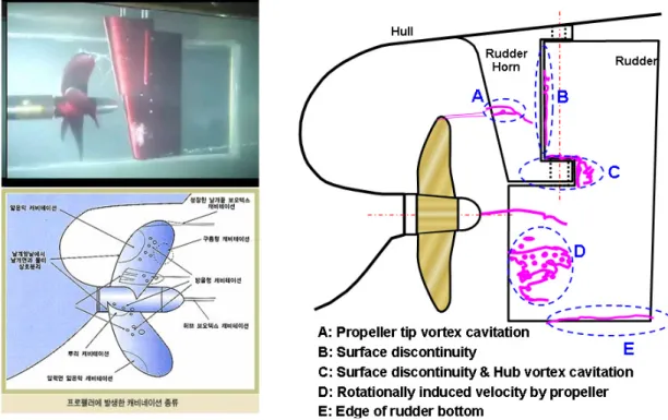
Erosion damage to rudder surface can be resulted from either impact erosion or cavitation erosion. The former is caused by direct impact of fluid jet stream on the rudder surface, whereas the latter is caused by shock wave due to collapse of cavitation induced bubble. From the point
Fig. 1. Schematic diagram of the cavitation erosion part for semi-spade rudder2)
of fluid dynamics, cavitation at the rudder surface can be generated either by the local, negative loading or by the vortex at the rudder shoe, as schematically shown in Fig.
1.2) The cavitation generated at the rudder surface will cause vibration and subsequent fatigue fracture of the rudder. As a countermeasure for these phenomena, several attempts have been made to optimize the fluid dynamic shape of the rudder, such as changing propeller design with minimized flow disturbance, elimination of surface discontinuity.
Despite continuous efforts to reduce premature rudder damage for last decades, however, protective organic coat- ing systems currently applied on the fast-going ships such as container carriers or naval vessel's rudders, propeller shaft struts, and other high-stress underwater hull areas often failed within a few months of their installation.
Premature corrosion due to failure of these protective coat- ings in underwater hull areas has been one of several cor- rosion issues related to high speed marine vessels.
Numerous on-site survey of the ships at the dry-dock re- vealed that the total affected area was typically up to ~ 40% of the total coated areas, and in most cases the most severe coating loss occurred in a localized area of the out- board sides of both rudders, as shown in Fig. 2.1) Coating loss resulting in exposed rudder shell plating and subsequent corrosion damage has been significant con- cerns for ship operators regarding the long-term safety of
the ships. Divers could perform partial coating touch-up and repair in the water, but major refurbishment and main- tenance of coating system should be carried out during dry-docking maintenance availabilities. Thus, corrosion damage to exposed rudder shell plating increases main- tenance costs and reduce the operation times of the ship, threatening the natural desires to lengthen the dry-docking cycle for improving the ships operational economic efficiency.
U.S. Navy has reported that coatings applied to these areas during both new construction and repair availabilities generally last about a year. According to U. S. Navy's Naval Sea Systems Command (NAVSEA)'s evaluation, typical recoating of rudders, struts, etc. costs the fleet from
$25,000 to well over $100,000 per occurrence per ship, depending on the surface preparation method used, the coating system selected, and the application process.1) Since these costs did not include the cost of repairing any damage to the substrate, it could be predicted that loss of the protective coating can allow metal loss and deterio- ration, increasing repair costs in dry-dock. The struts, rud- ders, and other erosion-prone areas of ships often require tougher and more resilient coating systems than other un- derwater hull applications due to the severity of the envi- ronment to which they are exposed. The coating system must not only provide protection from the corrosive sea- water environment, but also be able to withstand cavitation
Classification Materials / Product Name Specimen Name Remark
Metal Lining 316L Stainless Steel STS 316L -
Metal Coating (HVOF)
Stainless Steel 316L (Diamalloy 1104TM) TS_STS316L AF Exclusion Self Flux Alloy (Diamalloy 2001TM) TS_Self Flux AF Exclusion Amorphous Alloy (Amacor-MTM) TS_Amorphous AF Exclusion
Organic Coating
EH3250TM + AF795HTM Conventional AF Inclusion
DuraToughTM DL (Elasto-Ceramic Polymer) Elastomer AF Inclusion ScotchWeldTM 2216 (Epoxy Adhesive) Special Epoxy -
Si-Type Anti-Fouling Silicon AF -
Table 1. Selected material for cavitation erosion test
tion. As for the former approach, several materials have been repeatedly proposed and tested both in the laboratory and field condition by several research groups. In these attempts, high hardness organic or inorganic coating mate- rials were applied on the rudder surface with various meth- ods, such as metal spray, ceramic-metal coating.3)-8) The latter approach also has been issued in several cases. For
Fig. 2. Typical cavitation induced corrosion damage of ship's rudder1)
far mainly due to lack of successful, better coating materi- als with proven service record.
3. Experimental methods
3.1 Selection of candidate materials
Total seven different types of coating materials were selected for evaluation, which are 316L type austenitic stainless steel, 3 types of metallic alloys for HVOF (High Velocity Oxy Fuel) metal spray applications, and organic coatings of ScotchWeldTM 2216, DuraToughTM DL, Si-type Foul Resistant (FR) paints, as shown in Table 1.
Conventional protective coatings system, AC epoxy + AF (EH3250TM + AF795HTM), which has been widely used in the new-building shipyards, was also evaluated as a reference.
3.2 Testing of cavitation resistance
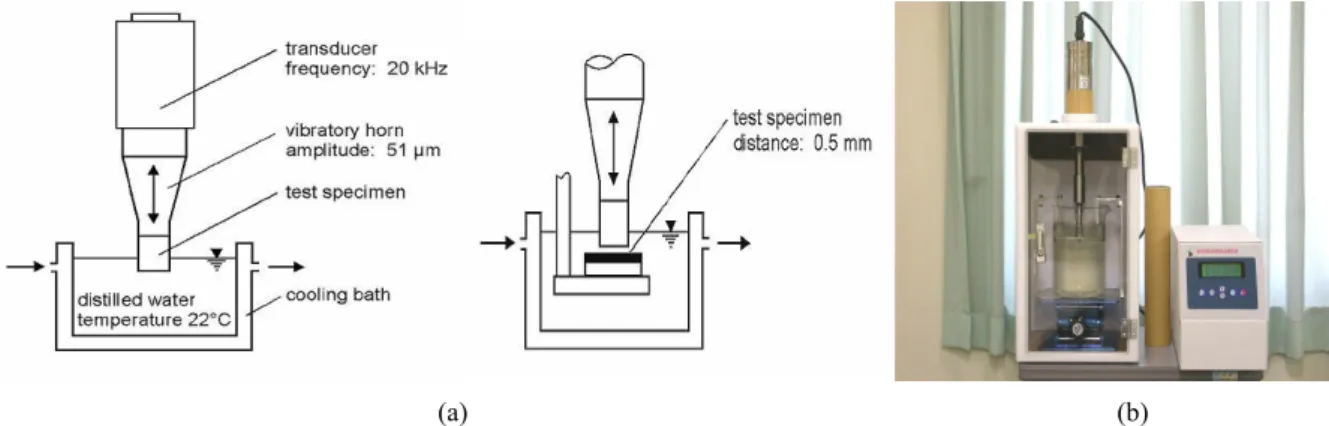
Cavitation resistance of each coating sample was eval- uated by using both an ultrasonic tester (modified ASTM G-32 method) and in-house built water jet tester. In case of the ultrasonic tester, as shown in Fig. 3(a), samples were placed 0.5 mm below the sonic generator, i.e., vi- bratory horn, to eliminate vibration induced damage to the coating layer. This arrangement has been known to provide more increased vibration amplitude to the surface to be tested. The actual tester, employed in this test, is shown
(a) (b) Fig. 3. (a) Schematic diagram, (b) photograph of vibratory cavitation erosion tester
Fig. 4. Water-jet cavitation erosion tester
in Fig. 3(b).
In order to simulate high impact cavitation expected from larger propellers, which were employed in actual ship operation, an in-house built water jet tester was also employed. The tester, as shown in Fig. 4, utilized a high pressure pump to generate high speed water jet impact in a vertical direction to the coating surface. In order to facilitate the erosion observation during the tests, monitor- ing window was installed directly on the water jet/coating surface contact area.
Cavitation resistance behavior of each coating was eval- uated by employing the concept of Cumulative Mean Depth of Erosion (CMDE) and erosion rate, which were taken after the preset testing duration. CDME can be in- duced the following equation 1 as follow;
CMDE(μm) = ∑ MDE(μm)
MDE(μm) = ΔW / 10ρA (1)
in which, coating's density ρ(g/cm3), exposed area A(cm2) and weight change ΔW(mg) are used for calculation.
Erosion rate, on the other hand, was evaluated as Mean Depth of Erosion (MDE), which can be induced using the following equation 2;
Erosion Rate(μm/min.) = MDE / Δt (2)
in which, Δt is the test duration.
Finally, the expectant useful life of each coating against erosion was evaluated by measuring the time required for the CMDE value to reach 100 μm and 200 μm.
3.3 Preparation of coating samples
Testing samples were applied or sprayed on butt end of 316L stainless steel mounting sets, as shown in Fig.
5, following ASTM G 32-02 standard, of which diameter was 15.9 ± 0.05 mm, 10 ± 0.5 mm, for ultra sonic testing and water jet testing, respectively. Before application of each coating, the surface of each mounting set was grit blasted to ISO Sa 2.5 grade and degreased with acetone, then the coatings were sprayed following recommended dry film thickness. In Table 2, the mechanical properties of the selected coatings were summarized.
(a) (b)
Fig. 5. Dimension of mounting set for cavitation erosion test;
(a) ultra sonar, (b) water-jet
Special Epoxy 0.75~0.85 0.75~0.80 HSA 93 1.325 Silicon AF 0.60 0.55~0.60 HSA 84 1.6
*97% of theoretical density **98% of theoretical density
4. Results and discussions
4.1 Ultra sonar test
Fig. 6 and Fig. 7 shows the ultra sonic test results for each coating after 10 hours of exposure in terms of MDE and erosion rate, respectively. As expected, the conven- tional organic coating suffered heavy erosion during the initial one hour duration, revealing its poor resistance of the coating layer. Other coatings also showed gradual progress of the erosion during the 10 hour test.
0 200 400 600 800 1000 1200
0 100 200 300 400 500 600
Time, min.
CMDE
, μ
m
STS316L TS_STS316L TS_Amorphous Elastom er Special Epoxy
Fig. 6. Cumulative Mean Depth of coatings: ultra sonar test
0.00 2.00 4.00 6.00 8.00 10.00
0 100 200 300 400 500 600
Time, min.
Erosion rate,
μm/min
STS316L TS_STS316L TS_Amorphous Elastom er Special Epoxy
Fig. 7. Erosion rate of coatings: ultra sonar test
the Table 2, also revealed that the degree of hardness did not fully matched with the coatings resistance to the ultra- sonic erosion, suggesting that surface hardness can not be a good screening indicator for coating materials selection against rudder cavitation protection. This might be sup- ported by the empirical opinion form the shipyards that coating's toughness, or the ability to absorb external impact would be simultaneously critical for the candidate ma- terials.
Fig. 8 shows the surface of each coating in the as- sprayed condition and after 10 hour ultra sonar tests. All coating samples showed a sign of erosion damage around their center, and the degree of erosion was different with each coating. As expected, among all coatings, the soft, conventional coatings (EH3250TM + AF795HTM) suffered the most severe erosion, exposing more than 20% of bare metal substrate after the test. This partially confirmed that the erosion condition of the current acceleration test is quite intensive in comparison with actual ship's service condition. The 316L stainless steel coating applied by HVOF metal spray (Diamalloy 1104) also experienced a partial loss of coated layer, partially exposing bare metal substrate after the erosion test. On the other hand, only slight erosion was observed for both 316 stainless steel plate and amorphous alloy coating applied by HVOF metal spray (Amacor-M), whereas more intensive erosion on the coating layer were observed for coatings made of an elas- to-ceramic polymer (DuraToughTM DL) and an epoxy ad- hesive (ScotchWeldTM 2216). Partial delamination of coat- ing was also observed for the epoxy adhesive coating.
The expectant useful life of each coating against erosion, as calculated by measuring the time required for the CMDE value to reach 100 μm and 200 μm, revealed the similar result in terms of each coating's erosion resistance characteristics. The soft, conventional coatings (EH3250TM + AF795HTM) reached to 100 μm CMDE value only in 4 minutes, and other coatings took longer time to reach that depth in the following order; 316L stainless steel by HVOF metal spray (24 min.) < Amorphous alloy coating by HVOF metal spray (63 min.) < Epoxy adhesive (155 min.) < Elasto-ceramic polymer (264 min.) < 316 stainless
STS 316L TS-STS316L TS-Amorphous
Conventional (after 60 min.) Elastomer Special Epoxy
(a) Before
STS 316L TS-STS316L TS-Amorphous
Conventional (after 60 min.) Elastomer Special Epoxy
(b) After 660 min.
Fig. 8. Appearance of coatings before and after vibratory erosion test
steel plate (3,968 min.).
To reach 200 μm of the CMDE value, it took a little longer for each coating, but the trend was only slightly different; Conventional coatings (6 min.) < 316L stainless steel by HVOF metal spray (307 min.) < Epoxy adhesive (236 min.) < Amorphous alloy coating by HVOF metal spray (155 min.) < Elasto-ceramic polymer (415 min.) <
316 stainless steel plate (7,906 min.).
4.2 Water jet test
In the water jet test, high impact water jet was propelled
from 22 kg/cm2 capacity high pressure pump operated by a 5.5 kW/7.5 HP motor. The water jet, formed in the water reservoir maintained at the temperature range of 25±3℃, would vertically impact on the coating surface at the speed of ~ 60 knots through 6 mm diameter nozzle, in which the samples were located 150 mm apart from the nozzle's end.
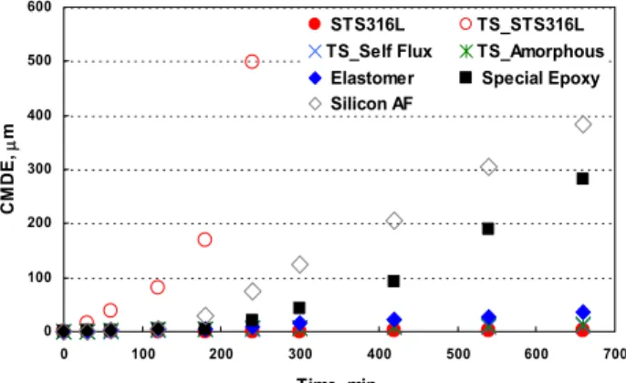
Fig. 9 and Fig. 10 shows cumulative Mean Depth of Erosion (MDE) and erosion rate of each coated sample measured from weight loss ΔW, after 11 hours of water jet test. The basic trend was quite similar to that already
Product Cost(₩/m2) Appliction
method Thickness Working Time
(270m2) Remark
Metal Spray Coating (HVOF)
STS316L
(Diamalloy 1003) 600,000 HVOF* 0.4~0.5mm < 7 day AF Excluded Self flux alloy
(Diamalloy 2001) 1,300,000 HVOF 0.4~0.5mm < 7 day AF Excluded Amorphous alloy
(Amacor-M) 1,200,000 HVOF 0.4~0.5mm < 7 day AF Excluded
Organic Coating
Conventional
(AC+SPCAF) 100,000 Spray 0.8~0.9mm < 7 day -
Elastomer
(Elasto-ceramic polymer) 1,300,000 Brush lining 1.6(2.4)mm < 7 day AF Included
Special Epoxy 200,000 Spray 0.75~0.8mm < 7 day AF Included
Silicon AF (AC+Si-AF) 150,000
~200,000 Spray 0.55~0.65mm < 7 day -
Metal
Lining STS316L 1,000,000
~1,300,000 Weld lining 5mm > 7 day(70m2) Galvanic corrosion Table 3. Cost estimation of selected coating materials
0 100 200 300 400 500 600 700
Time, min.
Fig. 9. Cumulative mean depth of coatings: water-jet test
0.0 1.0 2.0 3.0
0 100 200 300 400 500 600 700
Time, min.
Erosion rate, μm/min
STS316L TS_STS316L
TS_Self Flux TS_Amorphous Elastomer Special Epoxy Silicon AF
Fig. 10. Erosion rate of coatings: water-jet test
observed in the ultra sonar test, even though the time scale to reach to the severe erosion stage is somewhat different due to the difference in delivery mechanism of the me-
< Epoxy adhesive (430 min.) < Elasto-ceramic polymer (1,814 min.) < Amorphous alloy coating by HVOF metal spray (4,920 min.) < TS self flux alloy coating by HVOF metal spray (5,782 min.) < 316 stainless steel plate (29,438 min.).
To reach 200 μm of the CMDE value, it took a little longer for each coating, but the trend was only slightly different; Conventional coatings (7 min.) < 316L stainless steel by HVOF metal spray (186 min.) < Si-AF coating (413 min.) < Epoxy adhesive (552 min.) < Elasto-ceramic polymer (3,587 min.) < Amorphous alloy coating by HVOF metal spray (9,895 min.) < TS self flux alloy coat- ing by HVOF metal spray (11,596 min.) < 316 stainless steel plate (58,850 min.).
4.3 Economic viability of coating materials
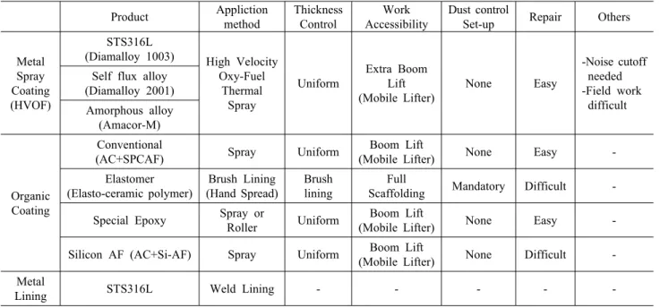
For optimal selection of cavitation resistant coating ma- terials, another two significant criteria are economical fea- sibility and working condition. In the selection procedure, the total cost and easiness in application and maintenance in field condition, such as surface preparation requirement,
Product Appliction method
Thickness Control
Work Accessibility
Dust control
Set-up Repair Others
Metal Spray Coating (HVOF)
STS316L
(Diamalloy 1003) High Velocity Oxy-Fuel
Thermal Spray
Uniform
Extra Boom Lift (Mobile Lifter)
None Easy
-Noise cutoff needed -Field work difficult Self flux alloy
(Diamalloy 2001) Amorphous alloy
(Amacor-M)
Organic Coating
Conventional
(AC+SPCAF) Spray Uniform Boom Lift
(Mobile Lifter) None Easy -
Elastomer (Elasto-ceramic polymer)
Brush Lining (Hand Spread)
Brush lining
Full
Scaffolding Mandatory Difficult - Special Epoxy Spray or
Roller Uniform Boom Lift
(Mobile Lifter) None Easy -
Silicon AF (AC+Si-AF) Spray Uniform Boom Lift
(Mobile Lifter) None Difficult - Metal
Lining STS316L Weld Lining - - - - -
Table 4. Workability comparison of selected coating materials
application equipment as well as environmental condition, should be thoroughly reviewed. In Table 3 and Table 4, the estimated total cost of each candidate materials and their workability are summarized, respectively.
The 316L stainless steel plate, which showed the best erosion resistance in the acceleration test, has been known to be quite expensive material compared to other coatings.
In terms of the installation method, additional, extensive cost and time required for special welding for 316L stain- less steel, are another disadvantage to other methods. All other coatings cover in this study, on the other hand, can be sprayed in a rather short period.
The HVOF spray coating procedure, however, also re- tain another disadvantage due to the special equipment re- quirement, which is generally heavy and lacks mobility in the actual field condition. Moreover, generally ship yard's dry dock is known to be a less ideal environment for such rather complicated work. High cost for the HVOF powders is another difficulty for wider use of this technol- ogy for rudder protection.
The organic coatings showed much better flexibility in terms of cost and workability. Especially, the epoxy adhe- sive, such as ScotchWeldTM 2216, which showed much better erosion resistance than the conventional coating, can be a proper choice, since it can be sprayed in shipyard dry docks with a single component airless pump, and re- pair of the coatings can be done with less difficulty. The total cost of the epoxy adhesive will be another advantage against other candidates. However, it still needs finer eval- uation regarding their long term cavitation resistance in-
cluding actual field test, which is the foremost, intrinsic requirement for this purpose.
5. Conclusions
As an alternative to existing rudder & hull protection system, several organic/inorganic coating materials, which are commercially available, were tested in terms of cav- itation resistance. Both standard ultrasonic tester and in-house developed ultra water jet test method were em- ployed as a means to evaluate their performance against cavitation induced damages. In terms of cavitation resist- ance, the performance was increased in the following or- der;
Conventional organic coatings < 316L stainless steel by HVOF metal spray < Si-AF coating < Epoxy adhesive
< Elasto-ceramic polymer < Amorphous alloy coating by HVOF metal spray < TS self flux alloy coating by HVOF metal spray < 316 stainless steel plate (58,850 min.).
In the consideration of overall cost and workability in the ship yard dry dock, the epoxy adhesive having better erosion resistance than the conventional coating, exhibited good sprayability with a single component airless pump at relatively lower total cost.
References
1. http://www.nstcenter.com/: Coating Systems for Struts, Rudders, and Other Erosion-Prone Areas.
2. J. M. Han, D. S. Kong, I. M. Song, and C. S. Lee, Proc.
Cavitation 2001, p.1-8, Session B9.005 (2001).