Strains around distally inclined implants retaining mandibular overdentures with Locator attachments: an in vitro study
Moustafa Abdou Elsyad1*, Fathi Abo Setta2, Ahmed Samir Khirallah1
1Removable Prosthodontics, Faculty of Dentistry, Mansoura University, Egypt
2Bachelor degree student, Faculty of Dentistry, Tripoli University, Libya
PURPOSE. The aim of the present study was to evaluate, by means of strain gauge analysis, the effect of different implant angulations on strains around two implants retaining mandibular overdenture with Locator attachments.
MATERIALS AND METHODS. Four duplicate mandibular acrylic models were constructed. Two implants were inserted in the canine regions using the following degrees of distal inclinations: group I (control); 0o, group II;
10o, group III; 20o, and group IV; 30o. Locator pink attachments were used to connect the overdenture to the implants and Locator red (designed for severely angled implants) was used for group IV (group IVred). For each group, two linear strain gauges were attached at the mesial and distal surfaces of the acrylic resin around each implant. Peri-implant strain was measured on loading and non-loading sides during bilateral and unilateral loading. RESULTS. For all groups, the mesial surfaces of the implants at loading and non-loading sides experienced compressive (negative) strains, while the distal implant surfaces showed tensile (positive) strains.
Group IV showed the highest strain, followed by group III, group II. Both group I and group IVred showed the lowest strain. The strain gauges at the mesial surface of the loading side recorded the highest strain, and the distal surface at non-loading side showed the lowest strain. Unilateral loading recorded significantly higher strain than bilateral loading. CONCLUSION. Peri-implant strains around two implants used to retain mandibular
overdentures with Locator attachments increase as distal implant inclination increases, except when red nylon inserts were used. [J Adv Prosthodont 2016;8:116-24]
KEY WORDS: Strain; Inclined implants; Locator; Overdentures
INTRODUCTION
The implant-retained overdenture has become an accepted and predictable treatment modality for edentulous patients because of its significant improvement in retention and sta- bility.1 According to the McGill consensus statement2 on overdentures, such prosthesis should become the minimum
standard of care for the edentulous mandible. Several attachment systems may be used to retain overdentures to the implants, such as ball anchors, bars, magnets, and tele- scopic crowns.3
A prefabricated, self-aligning attachment system that maintains both vertical and hinge resiliency has recently been introduced and is called a Locator attachment.4 In this unique design of the Locator, the patrix (male) is the replaceable nylon insert on the undersurface of the over- denture. The matrix (female) is, accordingly, the overden- ture abutment on the implant.5 The Locator system has been promoted as an alternative to ball attachments, espe- cially when the interarch distance is inadequate6 to avoid the denture base deformation and fracture.7 Locator attach- ments provide the ability to control the degree of retention by changing their retentive elements.4 The Locators have extra advantages in complex cases, as they can compensate for severe angle misalignment (i.e. a divergence of up to 40
Corresponding author:
Moustafa Abdou Elsyad
Department of Removable Prosthodontic, Faculty of Dentistry, Mansoura University, #68 ElGomhoria Street, ElMansoura 35516, Egypt Tel. 20 0572353238: e-mail, [email protected]
Received September 10, 2015 / Last Revision November 2, 2015 / Accepted January 12, 2016
© 2016 The Korean Academy of Prosthodontics
This is an Open Access article distributed under the terms of the Creative Commons Attribution Non-Commercial License (http://creativecommons.
org/licenses/by-nc/3.0) which permits unrestricted non-commercial use, distribution, and reproduction in any medium, provided the original work is properly cited.
degrees between the implant and the connector system).8 During mastication, loads are transferred to alveolar bone surrounding the implants retaining overdentures. It is important not to cause excessive loads on the implants9 because it has been reported that excessive load may cause peri-implant bone loss through the induction of bone microdamage.10,11 A key factor for success or failure of den- tal implants is the manner in which stress is transferred to peri-implant bone.12
With respect to stress distribution, ideal insertion of the implants is known to be parallel to each other, parallel to the long axis of occlusal loading, and perpendicular to the occlusal plane.13,14 However, an inclined implant is required in certain clinical circumstances, e.g., to fit the implants into the remaining bone in case of mandibular resorption or lin- gual concavities or to optimize the anteroposterior spread of implants.15 Walton et al.16 reported that there was a ten- dency for less experienced surgeons to place implants incorrectly so that the implants diverged from each other (with a distal inclination) in the frontal plane.
The influence of different types of attachments on peri-implant stress has been sufficiently investigated.3,9,17-21 However, few studies reported the effect of implant incli- nation on the stress around implants retaining mandibular overdentures.19,22-24 Two of the previous studies19,23 were concerned about using the photoelastic stress analysis for the evaluation of peri-implant stresses around 3 implants inserted in the interforaminal areas to retain mandibular overdentures with different attachments (bars, ball, Locator and ERA attachments). Another study22 examined, by means of finite element analysis, the level and distribution of peri-implant bone stresses around mandibular two- implant overdentures with ball attachment system. In a recent study,24 the authors used photoelastic stress analysis for evaluating the stress distribution in mandibular bone surrounding 2 implants retaining mandibular overdenture with bar-clip attachments.
Al-Ghafli et al.25 investigated the effect of different degrees of mesial inclinations of 2 implants retaining over- dentures with Locator attachments. They concluded that implant angulations negatively affect attachment retention.
Similarly, Rabbani et al.26 evaluated the effect of cyclic dis- engagement on the retentive force and wear patterns of three Locator inserts (blue, pink, and clear) placed on mesi- ally angulated implants. They noted a rapid decrease in the retentive force after 720 cycles for all three inserts. Stephens et al.27 evaluated the effect of different degrees of distal implant inclination on the retention of two Locator blue inserts before and after in vitro simulation of 3 to 5 years of use. They found that the retention of Locator pairs was not impaired by inter-implant divergence of up to 20 degrees.
However, there has not been enough information to fully investigate the effect of implant angulation on the strains around implants connected to the overdentures with Locator attachments.
Accordingly, the aim of the present study was to evalu- ate of the effect of different implant angulations on peri-
implant strains under the Locator-retained mandibular overdenture using strain gauge method. The hypothesis was that there would be no significant difference in strains around implants inserted at different degrees.
MATERIALS AND METHODS
Four acrylic models were constructed by duplicating a man- dibular edentulous stone model (without undercuts) using heat cured acrylic resin.28,29 The base of each acrylic resin model was trimmed parallel to the anterior alveolar residual ridge. Each model was placed on the table of a parallome- ter milling device (BF 2, Bredent, GmbH&Co, KG, Senden, Germany). The drills of the parallometer milling device were held perpendicular to the occlusal surface of anterior alveolar residual ridge of each model.
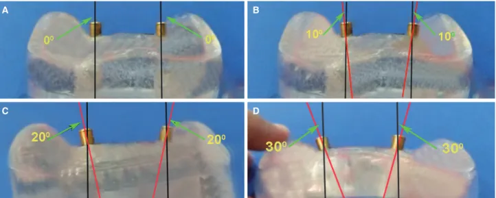
Two recesses were prepared at the canine regions using consecutive drills held at the following degrees of distal inclinations (away from midline): Model I (control); vertical to the residual ridge, Model II; 10°, Model III; 20°, and Model IV; 30°. The distal drill inclination was controlled using a conventional transparent plastic semicircular pro- tractor by placing it on the occlusal surface of the anterior alveolar residual ridge of each model (Fig. 1) to measure angles in degrees. Each implant recess inclination was established by pivoting the table of the milling device mesio-distally to match the long axis of each drill to the degree of the proposed implant inclination. Distal implant inclinations were completed by inserting two 3.7 × 13 mm laboratory implants (TioLogic, Dentaurum, Ispringen, Germany) in the prepared recesses with the help of Locator abut- ments that was screwed in the internal hex of the implants (Fig. 2).
Fig. 1. Controlling the degree of distal implant inclination using a conventional transparent plastic semicircular protractor.
For each model, an approximately 1.5-mm-thick layer of autopolymerized resilient silicone soft lining material (Softliner®, Promedica, GmbH, Neumünster, Germany) was used to mimic resilient edentulous ridge mucosa.18,30 Five mandibular record blocks were constructed over each model (total record blocks = 20). The occlusal plane of the record blocks was adjusted to the level of between the upper and middle third of the retromolar pad.31 Locator pink inserts (low retention; 1.365 g, TioLogic, Dentaurum, Ispringen, Germany) were used to connect the overden- tures to the implants (groups I to IV) and Locator red inserts (extra low retention; 680 g, designed by the manu- facture without internal frictional flange for increased implant angulations) were used for 30o implant angulation (group IV red).
The silicone soft liner material was removed from the implants using a sharp scalpel. For each group, two linear strain gauges (KFG-1-120-C1-11L1M2R; KYOWA elec- tronic instruments CO., Ltd., Tokyo, Japan; resistance 119.6
± 0.4 % Ω; gauge length: 1 mm; gauge factor: 2.08 ± 1.0
%) were attached using adhesive resin (CC-33A, EP-34B., KYOWA electronic instruments Co., Ltd.), at the mesial and distal surfaces of the acrylic resin around each implant.32 The gauges were labelled as follows; RD: distal side of the implants at loading side, RM: mesial side of the implants at loading side, LM: mesial side of the implants at non-loading side, and LD: distal side of the implants at non-loading side (Fig. 3). All gauges were positioned on the crest of the ridge in a mesiodistal direction perpendicular to the long axis of each implant.
The strain gauge lead wires (100 cm in length) were properly isolated and secured to the buccal surface of each model in specially prepared channels using a quick-set
adhesive to avoid any movement of the wires that may affect the accuracy of reading. For each model, acrylic dummy specimens were prepared as a control to receive four strain gauges in order to control any thermal changes resulting from loading. Free ends of the lead wires of the active (test) and dummy (control) strain gauges were twisted together and connected to form a half-circuit Wheatstone bridge (CSW-5A-05 switching box, Tokyo Sokki Kenkyujo Co., Ltd., Tokyo, Japan). The other half of the bridge was linked to a digital Strain meter (Tinsley and Co. Ltd., Werndee Hall, London, H. Model 8692), which electrically amplified the small signals of the strain gauge and convert- ed them into a voltage output.
Fig. 2. (A) Group I (0°) implant inclination, (B) Group II (10°) implant inclination, (C) Group III (20°) implant inclination, (D) Group IV (30°) implant inclination.
A B
C D
Fig. 3. The strain gauge positions around the implants.
The strain gauges were calibrated to determine the rela- tionship between the load applied and the strain signals received from the strain meter and to verify the repeatabili- ty of the readings of the gauges. A load ranged from 10 to 60 N was applied on the record block using a loading device.33
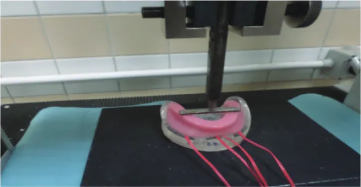
Each model was put on the compression grip of the universal testing machine and secured in position with the occlusal plane in a horizontal position. A digitized universal testing machine (LLOYD LRX, LLOYD instruments Ltd., Fareham, Hampshire, UK) was used to apply a vertical stat- ic load both unilaterally and bilaterally.9,32,33 For bilateral load application, a metal bar (6 cm in length, 1 cm in width, and 2 mm in thickness) was positioned in the region of the first molars on the occlusion rim between the right and left denture bases. The forces were delivered to the center of the metal bar using a loading pin (applicator) (Fig. 4). For unilateral load application, the right side of the overdenture was considered the loading side, while the left side was con- sidered the non-loaded side. The point of load application was on the central fossa of the 1st molar and was notched with a diamond bur (Fig. 5). This was done for reproduc- ibility, accommodating the tip of the loading pin on the same location (notch), and preventing slippage of the pin32,33 All measurements were repeated 5 times for each overdenture, allowing at least 5 minutes for heat dissipation,
and the mean of the recorded microstrains was calculated.
Two-way ANOVA was used to compare the recorded microstrain values between different groups (I, II, III, IV, and IVred) and between different sites of measurements (RD, RM, LM, and LD), followed by post hoc (Bonferroni) test for multiple comparisons. To compare the recorded microstrain values between loading applications, paired sample t test was used. P value was significant if it was less than 0.05 at confidence interval 95%. The SPSS statistical package for social science version 22 (SPSS Inc., Chicago, IL, USA) was used for data analysis.
RESULTS
Twenty mandibular record blocks were calculated to yield a power of 98% with a type I error of 0.05 (One way ANOVA with (µ) strain is the independent variable) using a comput- er program (Power and precision version 3, 2007, Biostat, Englewood, USA) for a statistically significant minimum difference of 32 in mean (µ) strain between groups (effect size = 1.28 and SD = 30). For all groups, mesial peri- implant sites at loading and non-loading sides experienced compressive (negative) strains, while distal implant sites showed tensile (positive) strains.
Comparisons of all microstrain values between groups, between the sites of strain gauges, and between load appli- cations are presented in Table 1, Table 2, and Table 3, respectively. Significant differences were detected between groups, the sites of strain gauges, and load applications (P
= .00). Group IV recorded the highest strain, followed by group III, group II, and both group I and IVred recorded the lowest strain (Table 1). RM sites recorded the highest strain, followed by RM, and LM and LD recorded the low- est strain (Table 2). Unilateral loading recorded a signifi- cantly higher strain than bilateral loading (Table 3).
Comparisons of peri-implant strains between groups are presented in Table 4 and Table 5. At different sites of strain gauges (RD, RM, LM and LD) during unilateral and bilateral load applications, group IV demonstrated the high- est peri-implant strain, followed by group III and group II.
The lowest strain was recorded at group I and group IVred Fig. 4. Bilateral load application.
Fig. 5. Unilateral load application.
Table 1. Comparison of total microstrains between groups
Group Mean St. error ANOVA
P value
Post hoc test (Bonferroni)
I -31.875 6.685
.00*
A
II -105.250 6.685 B
III -147.925 6.685 C
IV -220.750 6.685 D
IVred -30.375 6.685 A
* P is significant at 0.05 level of significance. The different upper case letters indicate significant differences between groups.
without significant differences. As the angle of implant inclination increases, the peri-implant strains also increase at different sites of strain gauges except when red nylon insert was used
Comparisons of peri-implant strains between sites of strain gauges are presented in Table 4 and Table 5. During
unilateral load application, the highest strain was recorded at RM for all groups and the lowest strain was noted at LD.
During bilateral load application, the highest strain was recorded at RM for all groups (except group II), and the lowest strains were recorded at LM for groups I and IVred and at LD for groups II, III, and IV.
Table 2. Comparison of total microstrains between sites of strain gauges
Group Mean St. error ANOVA
P value
Post hoc test (Bonferroni) RD (right distal) 472.100 5.979
.00*
A
RM (right mesial) -784.400 5.979 B
LM (left mesial) -299.400 5.979 C
LD (left distal) 182.760 5.979 D
* P is significant at 0.05 level of significance. The different upper case letters indicate significant differences between sites.
Table 3. Comparison of recorded microstrain values between unilateral and bilateral load application
Mean St. error Paired samples t test Unilateral load
application -144.870 4.228 Bilateral load .00*
application -69.600 4.228
* P is significant at 5% level.
Table 4. Comparison of peri-implant stain between groups and between sites of strain gauges during bilateral load application
Group
RD (right distal)
RM (right mesial)
LM (left mesial)
LD
(left distal) 2-way ANOVA (X ± SD)
I 99.00 ± 2.23A,a -156.00 ± 2.23A,b -89.00 ± 4.18A,c 134.00 ± 2.23A,a .00*
II 169.00 ± 220.32B,a -246.00 ± 14.74B,b -304.00 ± 29.66B,c 50.00 ± 10.60B,d .00*
III 961.00 ± 66.93C,a -1220.00 ± 57.00C,b -408.00 ± 13.03C,c 120.00 ± 15.81C,d .00*
IV 1048.00 ± 5.70D,a -1428.00 ± 28.19D,b -309.00 ± 4.18D,c 193.00 ± 2.73D,d .00*
IVred 94.00 ± 4.18A,a -147.00 ± 7.58A,b -84.00 ± 4.18A,c 131.00 ± 2.23A,d .00*
2-way ANOVA (P) .00* .00* .00* .00*
X; mean, SD; standard deviation, LSD; least significant differences. The different upper case letters indicate significant. The different upper case letters indicate significant differences between groups (Bonferroni, P < .05). The different lower case letters indicate significant differences between sites of strain gauges (Bonferroni, P
< .05). * P is significant at 5% level of significance.
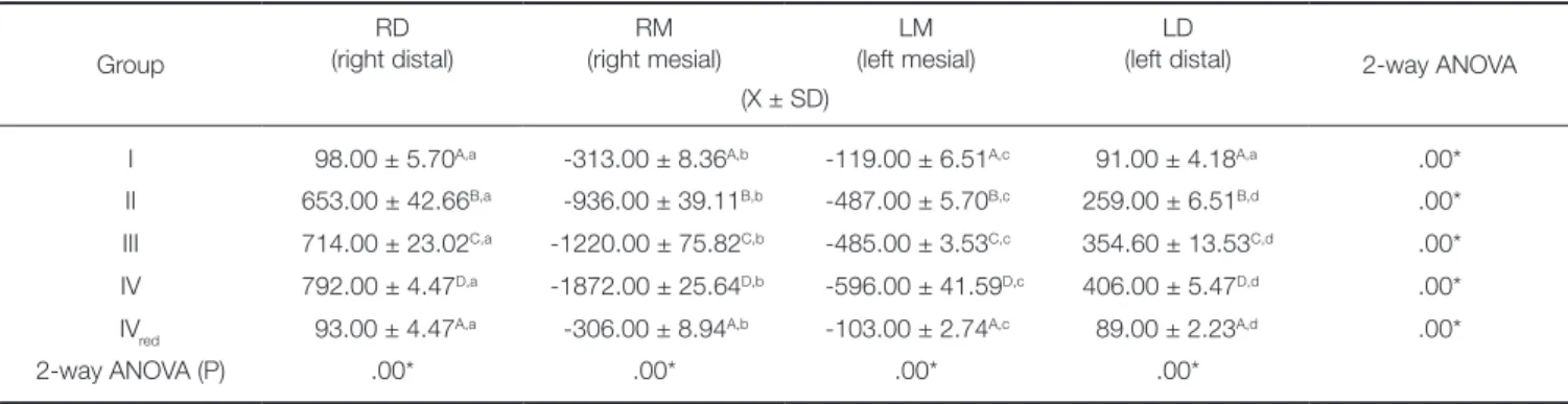
Table 5. Comparison of peri-implant stain between groups and between sites of strain gauges during unilateral load application
Group
RD (right distal)
RM (right mesial)
LM (left mesial)
LD
(left distal) 2-way ANOVA (X ± SD)
I 98.00 ± 5.70A,a -313.00 ± 8.36A,b -119.00 ± 6.51A,c 91.00 ± 4.18A,a .00*
II 653.00 ± 42.66B,a -936.00 ± 39.11B,b -487.00 ± 5.70B,c 259.00 ± 6.51B,d .00*
III 714.00 ± 23.02C,a -1220.00 ± 75.82C,b -485.00 ± 3.53C,c 354.60 ± 13.53C,d .00*
IV 792.00 ± 4.47D,a -1872.00 ± 25.64D,b -596.00 ± 41.59D,c 406.00 ± 5.47D,d .00*
IVred 93.00 ± 4.47A,a -306.00 ± 8.94A,b -103.00 ± 2.74A,c 89.00 ± 2.23A,d .00*
2-way ANOVA (P) .00* .00* .00* .00*
X; mean, SD; standard deviation, LSD; least significant differences. The different upper case letters indicate significant differences between groups (Bonferroni, P <
.05). The different lower case letters indicate significant differences between sites of strain gauges (Bonferroni, P < .05). * P is significant at 5% level of significance.
For groups I and IVred, bilateral loading showed higher association with increased strains than unilateral loading at RD and LD sites, and unilateral load showed higher strains than bilateral load at RM and LM. For groups II, III and IV, unilateral loading showed higher association with strain increase than bilateral loading at the majority of the strain gauge sites.
DISCUSSION
Distal implant inclination was performed in the present study after referring to the study of Walton et al.16 reporting that less experienced surgeons had a significantly greater tendency to place implants incorrectly so that the implants diverged from each other in the frontal plane (with a distal inclination). This distal implant inclination was also used in other studies concerned with the evaluation of peri-implant stresses19,22-24,34 and retention forces27,35 of attachment used with angulated implants to retain overdentures.
The following degrees of implant inclination were used:
0°, 10°, 20° and 30°. Similar degrees of implant inclinations were also used in other studies23,36,37 evaluating the effect of different implant inclinations on peri-implant stresses and retention of overdenture attachments. The degree of distal inclination was controlled using a conventional transparent plastic semicircular protractor, a procedure similar to a pre- vious study38 in which the author analyzed the influence of implant inclination on marginal bone loss for freestanding, implant-supported fixed partial dentures. In the study, the mesio-distal inclination of the implants, in relation to a ver- tical axis perpendicular to the occlusal plane, was measured with a protractor.
It was assumed that the strain measured on the bone sur- face could represent the stress introduced to the bone.18,39 Thus, two strain gauges were attached to the mesial and dis- tal sides of the acrylic resin surface around each implant.
The double frictional flange of the male nylon inserts with the locator abutments provides limited hinge movement,4 thus transmitting more stress to the implants during poste- rior loading.23 When the implants were angled and received perpendicular force on the overdenture occlusal plane, they tended to move in an inclined manner, so stress concentra- tion occurred along the mesial and distal faces of each implant.24 The use of 2 strain gauges around each implants to measure the strain around the implants was also men- tioned in other studies.32,33
In this study, vertical (axial) static loads were applied bilaterally to the central fossae of 1st molars. This is in agree- ment with Tokuhisa et al.,18 who mentioned that occlusal force tended to be concentrated around the molar region where the denture showed the largest movement. The load was applied bilaterally to reproduce centric occlusion in vivo.
The load was also applied unilaterally to reproduce unilater- al chewing on the working side. The red insert was used with 30°-inclined implants as it was designed for excessive implant angulation, while the other inserts (blue, pink, and clear) could be used for small implant inclinations up to 20
degrees between implants, as recommended by the manu- facturer.8,27
Group IV (30°, pink) demonstrated the highest peri- implant strain. In agreement with this finding, several biome- chanical studies22,24,40,41 also reported an increase in peri- implant stress with angled implants compared to vertically oriented implants. Watanabe et al.41 reported that, with angled implants, the force was not directed toward the long axis of the implant, causing an uneven distribution of the load, which resulted in an increase of the stress magnitudes.
Hong et al.22 found that, during bilateral or unilateral load application on the implants used to retain overdentures by ball attachments, the periimplant bone stress was the great- est around distally inclined implants (15°) and the lowest around buccally inclined implants (15°). The increased peri- implant strain with Locator attachments, used to retain mandibular overdentures to interforaminal implants insert- ed with different degrees of inclinations, was in line with the results of other studies.9,23,36 In another study,36 Locator blue was associated with increased retentive and lateral forces on the implants compared to ball anchors and mag- nets, especially with increased implant inclination (up to 30°).
The increased strain with Locator attachments may be attributed to the mode of retention of the Locator attach- ments, which is frictional contact that arises from a dimen- sional misfit between the slightly oversized nylon male insert and the smaller diameter of the inner ring of the female abutment.42 In clinical situations, the increased implant angulation may result in increased magnitude of micromotions around the 2 unsplinted implants. If these micromotions exceed 100 µm, they may result in greater bone turnover.43 The high strain values at the bone/implant interface with higher degrees of implant inclination are not desired, since they may cause bone loss through the induc- tion of bone microdamage.10,11
Group IVred (30°, red) showed the lowest strain when used on severely angled implants. This may be attributed to the absence of internal frictional flange of the red nylon insert. On the other hand, all pink nylon inserts have dou- ble (internal and external) frictional flanges that limit the hinge movement (8°),4 thus transmitting more stress to the implants than red inserts23 during posterior loading.
In the present study, all mesial peri-implant sites experi- enced compressive (negative) strains, while distal implant sites showed tensile (positive) strains. The residual ridge morphology might be responsible for the obtained stress pattern. The residual ridge had an upward slope towards the ramus. This might have caused a mesial shift of the denture base when the vertical force was applied on the first molar area.44 The nylon male element of the Locator attachments prevented the separation of the denture from the implants by the effect of the double frictional flanges, thereby transmitting the force in a mesial direction to the inclined implants. The mesial movement of the distally inclined implants resulted in the compression of the acrylic resin on the mesial surface of the implants, while the distal
surface of the implants was subjected to tensile strains.
The mesial side at the loading side was associated with the greatest strain. Again, the forward (mesial) shift of the mandibular denture base upon posterior load application could be responsible for the high strain on the mesial side of the loading side, as described previously. The mesial movement of the distally inclined implants compressed the acrylic resin mesially to the implants, resulting in a greater strain mesial to the implants surface arising from the com- pression resistance of the acrylic resin.24 In contrast, Pigozzo et al.24 reported that angled implants tended to move in an inclined manner when they received a perpendicular force on the overdenture occlusal plane. Therefore, stress con- centration occurred along the distal surface of the implant.
Also, Federick and Caputo19 found higher stress with the distal side of the inclined implants (divergently inclined 17°
from midline) used to retain overdentures with a bar and distal resilient cap attachments. Distal side of the non-load- ing side was associated with the lowest strain. Similarly, Hong et al.,22 found that stress values obtained from all inclined implants inserted in the canine region were lower in the non-loading side.
The increased strains with inclined implants became more evident with unilateral loading than bilateral loading.
This may be due to the higher shifting tendency of the den- ture base during unilateral loading than bilateral loading. In the bilateral loading, the denture may rotate around the ful- crum line passing between the implants placed in the canine areas and, due to the hinge movement of the Locator attachments, the loads may be absorbed by the silicone mucosa.
The major shortcoming of the in vitro stress analysis methods is the use of materials that frequently fail to simu- late the nature of living bone regarding mechano-biology and osseointegration.45 Therefore, the results of this study are only descriptive. Future biomechanical studies are rec- ommended to test the effect of different degrees of mesial, buccal, and lingual implant inclination on peri-implant stress around 2-implant overdentures retained by Locator attachments. Also, clinical research is still required to deter- mine the influence of different implant angulations on peri- implant tissue under these overdentures.
CONCLUSION
Within the limitation of this in vitro strain gauge analysis, peri-implant strain around 2 implants used to retain man- dibular overdentures with Locator attachments increases as the angle of distal implant inclination increases, except when red nylon inserts (without internal frictional flange) were used. If the implant displays high degree of inclina- tion, it is recommended to use nylon inserts designed for angled implants (red inserts) to minimize stress transfer to the peri-implant region.
ORCID
Moustafa Abdou Elsyad http://orcid.org/0000-0001-9514- 6931
REFERENCES
1. Mericske-Stern R, Zarb GA. Overdentures: an alternative im- plant methodology for edentulous patients. Int J Prosthodont 1993;6:203-8.
2. Feine JS, Carlsson GE, Awad MA, Chehade A, Duncan WJ, Gizani S, Head T, Lund JP, MacEntee M, Mericske-Stern R, Mojon P, Morais J, Naert I, Payne AG, Penrod J, Stoker GT Jr, Tawse-Smith A, Taylor TD, Thomason JM, Thomson WM, Wismeijer D. The McGill Consensus Statement on Overdentures. Montreal, Quebec, Canada. May 24-25, 2002.
Int J Prosthodont 2002;15:413-4.
3. Heckmann SM, Winter W, Meyer M, Weber HP, Wichmann MG. Overdenture attachment selection and the loading of implant and denture-bearing area. Part 2: A methodical study using five types of attachment. Clin Oral Implants Res 2001;
12:640-7.
4. Chikunov I, Doan P, Vahidi F. Implant-retained partial over- denture with resilient attachments. J Prosthodont 2008;17:
141-8.
5. Kleis WK, Kämmerer PW, Hartmann S, Al-Nawas B, Wagner W. A comparison of three different attachment systems for mandibular two-implant overdentures: one-year report. Clin Implant Dent Relat Res 2010;12:209-18.
6. Krennmair G, Seemann R, Fazekas A, Ewers R, Piehslinger E. Patient preference and satisfaction with implant-supported mandibular overdentures retained with ball or locator attach- ments: a crossover clinical trial. Int J Oral Maxillofac Implants 2012;27:1560-8.
7. ELsyad MA, Errabti HM, Mustafa AZ. Mandibular Denture Base Deformation with Locator and Ball Attachments of Implant-Retained Overdentures. J Prosthodont. 2015 Sep 16.
doi: 10.1111/jopr.12356.
8. Sadig W. A comparative in vitro study on the retention and stability of implant-supported overdentures. Quintessence Int 2009;40:313-9.
9. Porter JA Jr, Petropoulos VC, Brunski JB. Comparison of load distribution for implant overdenture attachments. Int J Oral Maxillofac Implants 2002;17:651-62.
10. Duyck J, Rønold HJ, Van Oosterwyck H, Naert I, Vander Sloten J, Ellingsen JE. The influence of static and dynamic loading on marginal bone reactions around osseointegrated implants: an animal experimental study. Clin Oral Implants Res 2001;12:207-18.
11. Gotfredsen K, Berglundh T, Lindhe J. Bone reactions adja- cent to titanium implants subjected to static load of different duration. A study in the dog (III). Clin Oral Implants Res 2001;12:552-8.
12. Geng JP, Tan KB, Liu GR. Application of finite element analysis in implant dentistry: a review of the literature. J Prosthet Dent 2001;85:585-98.
13. Ogawa T, Dhaliwal S, Naert I, Mine A, Kronstrom M, Sasaki
K, Duyck J. Effect of tilted and short distal implants on axial forces and bending moments in implants supporting fixed dental prostheses: an in vitro study. Int J Prosthodont 2010;
23:566-73.
14. Krennmair G, Fürhauser R, Krainhöfner M, Weinländer M, Piehslinger E. Clinical outcome and prosthodontic compen- sation of tilted interforaminal implants for mandibular over- dentures. Int J Oral Maxillofac Implants 2005;20:923-9.
15. Krekmanov L, Kahn M, Rangert B, Lindström H. Tilting of posterior mandibular and maxillary implants for improved prosthesis support. Int J Oral Maxillofac Implants 2000;15:
405-14.
16. Walton JN, Huizinga SC, Peck CC. Implant angulation: a measurement technique, implant overdenture maintenance, and the influence of surgical experience. Int J Prosthodont 2001;14:523-30.
17. Sadowsky SJ, Caputo AA. Effect of anchorage systems and extension base contact on load transfer with mandibular im- plant-retained overdentures. Prosthet Dent 2000;84:327-34.
18. Tokuhisa M, Matsushita Y, Koyano K. In vitro study of a mandibular implant overdenture retained with ball, magnet, or bar attachments: comparison of load transfer and denture stability. Int J Prosthodont 2003;16:128-34.
19. Federick DR, Caputo AA. Effects of overdenture retention designs and implant orientations on load transfer characteris- tics. J Prosthet Dent 1996;76:624-32.
20. Kenney R, Richards MW. Photoelastic stress patterns pro- duced by implant-retained overdentures. J Prosthet Dent 1998;80:559-64.
21. Ichikawa T, Horiuchi M, Wigianto R, Matsumoto N. In vitro study of mandibular implant-retained overdentures: the in- fluence of stud attachments on load transfer to the implant and soft tissue. Int J Prosthodont 1996;9:394-9.
22. Hong HR, Pae A, Kim Y, Paek J, Kim HS, Kwon KR. Effect of implant position, angulation, and attachment height on peri-implant bone stress associated with mandibular two-im- plant overdentures: a finite element analysis. Int J Oral Maxillofac Implants 2012;27:e69-76.
23. Celik G, Uludag B. Photoelastic stress analysis of various re- tention mechanisms on 3-implant-retained mandibular over- dentures. J Prosthet Dent 2007;97:229-35.
24. Pigozzo MN, Laganá DC, Sesma N, Souza GF, Ichi AL.
Photoelastic stress analysis in mandibular bone surrounding bar-clip overdenture implants. Braz Oral Res 2014;28. pii:
S1806-83242013005000034.
25. Al-Ghafli SA, Michalakis KX, Hirayama H, Kang K. The in vitro effect of different implant angulations and cyclic dis- lodgement on the retentive properties of an overdenture at- tachment system. J Prosthet Dent 2009;102:140-7.
26. Rabbani S, Juszczyk AS, Clark RK, Radford DR. Investigation of retentive force reduction and wear of the locator attach- ment system with different implant angulations. Int J Oral Maxillofac Implants 2015;30:556-63.
27. Stephens GJ, di Vitale N, O’Sullivan E, McDonald A. The in- fluence of interimplant divergence on the retention character- istics of locator attachments, a laboratory study. J Prosthodont 2014;23:467-75.
28. Gonda T, Ikebe K, Dong J, Nokubi T. Effect of reinforce- ment on overdenture strain. J Dent Res 2007;86:667-71.
29. Dong J, Ikebe K, Gonda T, Nokubi T. Influence of abut- ment height on strain in a mandibular overdenture. J Oral Rehabil 2006;33:594-9.
30. el Charkawi HG, el Wakad MT. Effect of splinting on load distribution of extracoronal attachment with distal extension prosthesis in vitro. J Prosthet Dent 1996;76:315-20.
31. Takeshita S, Kanazawa M, Minakuchi S. Stress analysis of mandibular two-implant overdenture with different attach- ment systems. Dent Mater J 2011;30:928-34.
32. ELsyad MA, Elsaadawy MG, Abdou AM, Habib AA. Effect of different implant positions on strain developed around four implants supporting a mandibular overdenture with rigid telescopic copings. Quintessence Int 2013;44:679-86.
33. Elsyad MA, Al-Mahdy YF, Salloum MG, Elsaih EA. The ef- fect of cantilevered bar length on strain around two implants supporting a mandibular overdenture. Int J Oral Maxillofac Implants 2013;28:e143-50.
34. Uludag B, Polat S, Sahin V, Çomut AA. Effects of implant angulations and attachment configurations on the retentive forces of locator attachment-retained overdentures. Int J Oral Maxillofac Implants 2014;29:1053-7.
35. Evtimovska E, Masri R, Driscoll CF, Romberg E. The change in retentive values of locator attachments and hader clips over time. J Prosthodont 2009;18:479-83.
36. Yang TC, Maeda Y, Gonda T, Kotecha S. Attachment sys- tems for implant overdenture: influence of implant inclina- tion on retentive and lateral forces. Clin Oral Implants Res 2011;22:1315-9.
37. Gulizio MP, Agar JR, Kelly JR, Taylor TD. Effect of implant angulation upon retention of overdenture attachments. J Prosthodont 2005;14:3-11.
38. Koutouzis T, Wennström JL. Bone level changes at axial- and non-axial-positioned implants supporting fixed partial den- tures. A 5-year retrospective longitudinal study. Clin Oral Implants Res 2007;18:585-90.
39. Heckmann SM, Winter W, Meyer M, Weber HP, Wichmann MG. Overdenture attachment selection and the loading of implant and denture-bearing area. Part 1: In vivo verification of stereolithographic model. Clin Oral Implants Res 2001;12:
617-23.
40. Bevilacqua M, Tealdo T, Pera F, Menini M, Mossolov A, Drago C, Pera P. Three-dimensional finite element analysis of load transmission using different implant inclinations and cantilever lengths. Int J Prosthodont 2008;21:539-42.
41. Watanabe F, Hata Y, Komatsu S, Ramos TC, Fukuda H.
Finite element analysis of the influence of implant inclina- tion, loading position, and load direction on stress distribu- tion. Odontology 2003;91:31-6.
42. Alsabeeha N, Atieh M, Swain MV, Payne AG. Attachment systems for mandibular single-implant overdentures: an in vi- tro retention force investigation on different designs. Int J Prosthodont 2010;23:160-6.
43. Szmukler-Moncler S, Salama H, Reingewirtz Y, Dubruille JH.
Timing of loading and effect of micromotion on bone-den- tal implant interface: review of experimental literature. J
Biomed Mater Res 1998;43:192-203.
44. Feingold GM, Grant AA, Johnson W. The effect of variation of residual ridge angle on partial denture abutment tooth movement. J Oral Rehabil 1988;15:379-84.
45. Akça K, Cehreli MC, Iplikçioglu H. A comparison of three- dimensional finite element stress analysis with in vitro strain gauge measurements on dental implants. Int J Prosthodont 2002;15:115-21.