DOI https://doi.org/10.9725/kts.2020.36.3.133
섬유 방향에 따른 에폭시 기반 복합재의 마찰 및 마모 특성에 관한 연구
안효성1ㆍMahdi Khadem2ㆍ전흥재3†ㆍ김대은3††
1
연세대학교 대학원 기계공학과 석사과정생
2
연세대학교 대학원 기계공학과 박사과정생
3
연세대학교 기계공학과 교수
Effect of Fiber Orientation on the Friction and Wear Properties of Epoxy-based Composites
Hyo-Seong An
1, Mahdi Khadem
2, Heoung-Jae Chun
3†and Dae-Eun Kim
3††1
M.S Student, Graduate School, Dept. of Mechanical Engineering, Yonsei University
2
Ph.D. Student, Graduate School, Dept. of Mechanical Engineering, Yonsei University
3
Professor, Dept. of Mechanical Engineering, Yonsei University (Received May 14, 2020 ; Revised June 3, 2020 ; Accepted June 10, 2020)
Abstract − In this paper, we present an experimental investigation of the friction coefficient and wear area change of carbon/epoxy and E-glass/epoxy composites depending on the fiber direction (0°/90°). We compared the results of the case where the sliding direction is parallel to the fiber direction (0°) with that of the case where it is perpendicular to the fiber direction (90°). The ball-on-plate wear test equipment was used to cause wear in both directions. Two types of specimens were prepared with thicknesses of 3 mm—one made of carbon fiber reinforced plastic composite (CFRP) and the other of glass fiber reinforced plastic composite (GFRP). A normal force of 20 N was applied to the specimen and the sliding speed was 10 mm/s and the sliding distance was set to 20 m to perform the wear test. The CFRP demon- strates superior tribological characteristics compared to the GFRP. This outcome is attributed to graphitization of car- bon, which serves as solid lubricating particles. In addition, both CFRP and GFRP are worn more in the 90° direction than in the 0° direction. This is due to the greater occurrence of fiber breakage and separation in the 90° direction than in the 0° direction. This study is expected to be utilized as basic data for understanding the friction and wear char- acteristics of CFRP and GFRP composites along the fiber direction and to apply the appropriate material.
Keywords − carbon/Epoxy composite(탄소섬유 복합재), e-glass/epoxy composite(유리섬유 복합재), fiber orientation( 섬유 방향), friction coefficient(마찰 계수), wear(마모)
1. 서 론
복합재료는 높은 비강성, 높은 비강도 및 우수한 기계적 특성과 마모 특성으로 인해 자동차, 항공우주 등 다양한 산 업 분야에서 기존의 금속 재료를 대체하고 있다[1]. 특히
†
Corresponding author: Heoung-Jae Chun
Tel: +82-2-2123-4827, E-mail: [email protected] https://orcid.org/0000-0003-1484-3239
††
Corresponding author: Dae-Eun Kim
Tel: +82-2-2123-2822, E-mail: [email protected] https://orcid.org/0000-0002-6095-5138
https://orcid.org/0000-0001-8512-507X507X (Hyo-Seong An
1)
ⓒ Korean Tribology Society 2020. This is an open access article distributed under the terms of the Creative Commons Attribution License(CC BY, https://creativecommons.org/
licenses/by/4.0/), which permits unrestricted use, distribution, and reproduction of the work
in any medium, provided the original authors and source are properly cited.
광범위하게 활용할 수 있는 탄소 섬유와 유리 섬유의 경 우 베어링, 롤러, 기어 등과 같은 슬라이딩/롤링 부품에 적 용하기 위한 다양한 시도가 이루어지고 있다. 또한 유해 물질을 포함하지 않은 친환경 마찰재 개발을 위해 탄소 섬 유를 사용한 복합재의 마찰 및 마모 특성을 평가하는 연 구가 진행되고 있다[2]. 이에 따라 이방성 특징을 갖는 섬 유 강화 복합재의 복잡한 마모 거동에 대해 이해하는 것 은 효율적인 구조 설계에 있어 매우 중요한 부분이다.
여러 실험적인 연구에서 복합재의 마찰 계수와 마모율 은 수직 하중, 미끄럼 속도, 미끄럼 거리, 섬유 방향과 같 은 실험 조건에 의해 큰 영향을 받는 것으로 나타났다[3- 6]. 특히 복합재는 섬유 방향에 따라 큰 특성 차이를 보이 며 몇몇 연구에서 섬유 방향에 따른 마찰 및 마모 특성에 대해 실험적으로 분석하였다. Seong T. Woo와 Jae R.
Youn[7] 은 Chopped 탄소 섬유를 사용하여 다양한 섬유 배열을 갖는 복합재의 마찰 실험을 통해 섬유의 배열이 마모에 영향을 준다는 것을 확인하였다. Sung과 Suh[8]는 탄소 섬유, 케블라 섬유, 유리 섬유 복합재의 섬유 방향에 따른 마모 특성을 연구하였다. 실험 결과에 따르면 마모 및 마찰 계수는 마모 표면 특성에 따라 매우 다르게 나타 나며, 탄소 섬유의 경우 마모 방향이 섬유 방향에 수직일 때 마찰 계수와 마모율 모두 가장 낮게 발생하였다. 반면, Giltrow 와 Lancaster[9]의 연구에 따르면 섬유의 방향은 마 모 특성에 큰 영향을 주지 않으며 섬유의 종류와 상대 마 찰면의 마모막 형성이 마모 특성에 주된 영향을 주는 요 인이라고 분석하였다. 마모막이란 마모로 인해 부서진 섬 유와 모재의 입자들로 구성된 층을 말하며, 탄소 섬유의 경우 마모가 진행될수록 입자들이 더욱 잘고 부드럽게 갈 리어서 낮은 마찰 계수를 가지는 것으로 보고되었다. 또 한 Sharma와 Rao[10]는 탄소 섬유 복합재의 섬유 방향이 0
o에서 90
o로 15
o씩 증가할 때 마모 특성의 변화에 대해 연 구하였으며, 각도가 증가할수록 마찰 계수와 마모율 모두 증가한다는 것을 실험을 통해 증명하였다.
이렇듯 섬유 강화 복합재의 섬유 종류 및 방향에 따 른 상이한 연구 결과가 보고되어 왔으며, 각 연구의 마 모 실험 조건에 따라 결과도 민감하게 나타나는 것을 알 수 있었다. 따라서 본 연구에서는 활용도가 높은 탄소섬 유/에폭시와 유리섬유/에폭시 복합재의 0
o(Longitudinal) 및 90
o(Transverse) 방향으로 마모 실험을 진행하여 섬유 강화 복합재의 모재 종류와 섬유 방향에 따른 트라이볼 로지적 특성을 파악하였다.
2. 연구방법 및 내용
2-1. 복합재 시편 준비
섬유 방향에 따른 트라이볼로지적 특성을 비교 분석 하기 위해 일방향 탄소 섬유 및 유리 섬유 프리프레그 (Prepreg)를 250 mm × 250 mm로 자른 뒤 hand lay-up 방법으로 적층하여 Table 1과 같이 시편을 제작하였다.
적층된 복합재료는 압력 용기 (Autoclave) 내에서 압력 및 진공 상태에서 가열 경화 사이클에 따라 경화되었다 [11]. 경화 단계는 110
oC 에서 60분, 175
oC 에서 120분 순 서로 진행한 후 압력 용기 내에서 천천히 상온으로 식혔 다. 완성된 복합재 시편의 기계적 특성은 Table 2에 나 타내었다[12].
경화가 완료된 복합재 판은 다이아몬드 휠 커터를 사 용하여 Fig. 1과 같이 직육면체 시편 크기 25 mm × 25 mm
×3 mm로 가공하였다. 모든 시편의 마찰면은 degreaser, conditioner, neutralizer, DI(Deionized) water, air spray 순서로 세척하였다.
2-2. 실험 준비 및 부하 조건
Ball-on-plate 형식의 왕복운동형 마찰시험기를 사용하 였다. 본 실험 장치의 구성은 Fig. 2에 나타내었다. 지그 Table 1. Composite prepreg type and laminate
Prepreg
Type Grade Ply
Thickness
Stacking Sequence Carbon/Epoxy USN 125B 0.115 mm [0]
15sE-glass/Epoxy USN 200 0.162 mm [0]
10sTable 2. Composite laminate properties
Property USN 125B USN 200 Longitudinal modulus (0
o) 131 GPa 39.5 GPa Transverse modulus (90
o) 8.2 GPa 9.6 GPa
In-plane Shear modulus 4.5 GPa 4.1 GPa Poisson’s ratio 0.281 0.31 Tensile strength
in fiber-direction (0°) 2000 MPa 1140 MPa Tensile strength
in transverse-direction (90°) 61 MPa 39 MPa
Fig. 1. Test specimen details.
에 시편을 고정하고 5 mm 지름의 Steel ball tip을 사용 하여 수직 하중을 인가하였다.
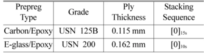
먼저 섬유 방향에 대한 영향을 확인할 수 있는 적절 한 조건을 찾기 위해 Table 3과 같이 조건을 변경하며 실 험을 진행하였다. Fig. 3과 같이 실험 조건 I에서는 마모 깊이 2.04 µm로 섬유가 잘린 모습을 관찰할 수 없었다.
실험 조건 II에서는 마모 깊이 8.28 µm로 표면의 스크래 치 형상이 관찰되었으나 섬유가 끊어진 모습은 관찰되 지 않았다. 따라서 마모 깊이 12.87 µm로 섬유의 마모 현상을 확인할 수 있는 실험 조건 III을 최종 조건으로 선정하였다.
모든 실험은 조건 III에서 진행하였으며, 섬유 방향에 대한 마찰 계수와 마모 면적 변화를 비교하였다. 시편의 마모면은 3D 레이저 공초점 현미경(3D laser confocal microscope) 으로 조사하여 파손된 섬유 등을 관찰하였다.
3. 결과 및 고찰
3-1. 섬유 방향에 따른 마찰 계수
섬유 방향에 따른 마찰 계수의 변화를 관찰하기 위해 Fig. 4 와 같이 마모 방향과 섬유 방향이 평행한 경우(0
o) 와 마모 방향과 섬유 방향이 수직인 경우(90
o) 에 대해 실험 을 진행하였다. 마찰 계수 결과는 Table 4에 나타냈었으
며, 각 실험마다 두 번씩 반복한 값의 평균을 사용하였다.
두 섬유 모두 Fig. 5에서 확인할 수 있듯이 실험 초기 에 마찰계수가 0.1 이하로 유지되는 구간이 나타났으며, 이후 사이클이 진행됨에 따라 마찰 계수가 증가하며 변 화하는 경향을 보였다. 이는 시편의 표면을 덮고 있는 에 폭시의 영향으로 분석되며, Fig. 3의 (a), (b)와 같이 실 험 전에는 표면의 에폭시로 인해 섬유가 보이지 않지만, (e) 에서 실험이 진행된 후 표면에 덮인 에폭시를 지나 섬 유가 손상된 것을 확인할 수 있다. 따라서 실험 초기에 낮 Fig. 2. Reciprocator experimental setup.
Table 3. Friction test condition
Condition Normal Force Total Cycles Sliding Speed
I 3N 3000 8 mm/s
II 10N 3000 8 mm/s
III 20N 5000 10 mm/s
Fig. 3. 3D laser confocal microscope image (a) Carbon/
Epoxy specimen surface, (b) E-glass/Epoxy specimen surface, (c) Condition I worn surface, (d) Condition II worn surface, (e) Condition III worn surface, (f) Steel ball tip worn surface.
Table 4. Friction coefficient of Carbon/Epoxy and E-glass/
Epoxy specimen
Sliding Direction Carbon/Epoxy E-glass/Epoxy
0
o0.22 0.30
90
o0.28 0.31
Fig. 4. Fiber orientation angles with respect to sliding
directions (a) 0° (b) 90°.
은 마찰 계수가 나타나는 구간은 표면의 에폭시 층에서 마모가 진행되는 구간이며, 이후 일정 사이클이 진행됨에 따라 Fig. 3의 (f)와 같이 Steel ball tip 표면에 마모 입자 가 발생하고, 이와 함께 에폭시 층을 지나 섬유에서 마모 가 진행되며 마찰 계수가 증가하는 것으로 분석된다. 낮 은 마찰 계수 구간이 유지되는 시간은 각 시편 표면의 에 폭시 층 두께에 따라 다르게 나타나는 것으로 보인다.
3-1-1. 탄소/에폭시 복합재
탄소/에폭시 복합재의 경우, Fig. 5의 (a)와 같이 초기 의 낮은 마찰 계수 구간 이후 마찰 계수가 증가하다가 슬 라이딩 거리에 따라 서서히 감소하는 경향을 보였다. 이 는 탄소 섬유의 원자 구조가 흑연과 동일하여 마모가 발
생함에 따라 슬립 현상에 의해 탄소 섬유의 마모 입자들 이 고체 윤활과 같은 역할을 해주어 나타나는 현상으로 보인다. 즉, 에폭시와 탄소 섬유에서 마모가 진행되며 마 찰 계수가 증가하다가 탄소 섬유의 고체 윤활 영향으로 인해 서서히 마찰 계수가 감소하는 것으로 분석된다.
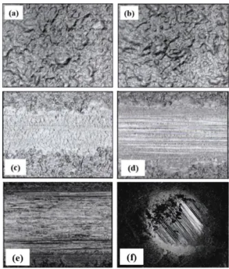
또한 0
o비해 90
o조건에서 평균 마찰 계수가 더 높게 나타났다. 이는 Fig. 6의 마모면에서 관찰된 것과 같이 0
o에 비해 90
o마모면에서 더욱 많은 섬유가 이탈하여 랜 덤하게 배치되어 있는 것을 확인할 수 있다. 이러한 섬 유의 파손과 이탈로 인해 마찰 계수가 더욱 높게 나타나 는 것으로 판단된다. 반면 0
o마모면에서는 비교적 섬유 의 이탈이 적은 것을 확인하였다.
Fig. 6. Worn surface (a) Carbon/Epoxy 0°, (b) Carbon/Epoxy 90°, (c) E-glass/Epoxy 0°, (d) E-glass/Epoxy 90°.
Fig. 5. Friction coefficient graph according to fiber orientation 0° and 90° for (a) Carbon/Epoxy, (b) E-glass/
Epoxy specimens.
3-1-2. 유리/에폭시 복합재
유리/에폭시 복합재의 경우, Fig. 5의 (b)와 같이 초기 의 낮은 마찰 계수 구간 이후 마찰 계수가 증가하다가 슬 라이딩 거리에 따라 비교적 불안정한 변화를 보였다. 이 는 탄소 섬유에 비해 취성이 강한 유리 섬유의 특징으로, 부서진 섬유의 마모 입자에 의해 복잡한 거동을 나타내 는 것으로 보인다. 섬유 방향에 따른 평균 마찰 계수는 큰 차이가 없었으며, 이는 탄소 섬유에 비해 낮은 탄성 계수와 강도로 인해 해당 마모 실험 조건에서 적절한 특 성 차이를 확인할 수 없는 것으로 판단된다. Fig. 6의 (a) 와 (c)에서 관찰된 것과 같이 0
o방향 마모면에서 탄소 섬유에 비해 많은 섬유가 끊어진 것을 확인할 수 있다.
또한 탄소 섬유와 유사하게 0
o에 비해 90
o마모면에서 더 욱 많은 섬유가 이탈하여 랜덤하게 배치된 것을 관찰할 수 있다.
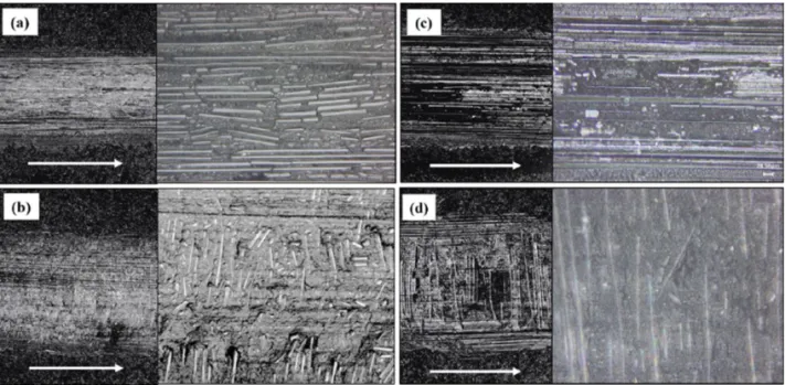
3-2. 섬유 방향에 따른 마모 면적
실험 후 마모된 시편 표면을 3D 레이저 공초점 현미 경으로 분석하였다. Fig. 7과 같이 각 시편의 마모 면적 을 구하였으며, 탄소/에폭시 시편과 유리/에폭시 시편 모 두 90
o에서 마모 면적이 증가하였다. 또한 0
o에서 더욱 거 친 단면 형상을 확인할 수 있었다. 이는 앞서 분석한 것
과 같이 90
o방향이 0
o에 비해 이탈하는 섬유가 많아 나 타나는 결과로 보인다. 측정한 마모 면적은 Table 5에 나 타내었다.
탄소/에폭시 시편이 유리/에폭시 시편에 비해 마모 면 적이 작게 측정되었는데, 이는 비교적 탄성계수와 강도 가 높은 탄소 섬유가 마모에 대한 저항성이 높아 나타나 는 결과로 분석된다.
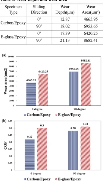
탄소/에폭시 시편과 유리/에폭시 시편의 마찰 계수 및 마모 면적을 비교한 그래프를 Fig. 8에 나타내었다. 0
o및 90
o방향 모든 경우에서 탄소 섬유 복합재의 마찰 계수 가 더욱 낮게 나타났으며, 마모 면적 또한 작게 측정된 것을 확인할 수 있다. Fig. 8에 나타난 관계를 바탕으로 마찰 계수가 높아짐에 따라 마모 면적 또한 높아지는 것 Fig. 7. Worn surface profile (a) Carbon/Epoxy 0°. (b)
Carbon/Epoxy 90° (c) E-glass/Epoxy 0°. (d) E-glass/
Epoxy 90°.
Table 5. Wear depth and wear area Specimen
Type
Sliding Direction
Wear Depth(µm)
Wear Area(µm
2) Carbon/Epoxy 0
o12.87 4665.95
90
o18.02 6953.65 E-glass/Epoxy 0
o17.39 6420.25 90
o21.13 8682.41
Fig. 8. (a) Wear area of Carbon/Epoxy and E-glass/
Epoxy, (b) Friction Coefficient of Carbon/Epoxy and
E-glass/Epoxy.
을 확인할 수 있으며, 이를 통해 마찰 계수 또한 마모 면 적에 영향을 주는 인자로 판단된다.
4. 결 론
본 연구에서는 일방향 탄소/에폭시와 유리/에폭시 복 합재의 섬유 방향에 따른 마찰 및 마모 특성을 비교 분 석하였으며, 다음과 같은 결론을 얻었다.
- 섬유 강화 복합재의 경우, 마찰 및 마모 특성은 사용 하는 섬유의 종류와 섬유 방향에 의존적이다.
- 유리 섬유 복합재에 비해 탄소 섬유 복합재의 트라 이볼로지적 특성이 우수한 것으로 나타났다.
- 섬유 방향에 따른 마찰 계수는 마모 방향과 섬유 방 향이 평행한 경우(0
o) 가 마모 방향과 섬유 방향이 수직 한 경우(90
o) 보다 우수한 것으로 나타났다.
- 섬유 방향에 따른 마모 면적은 마모 방향과 섬유 방 향이 수직한 경우(90
o) 에 크게 측정되었으며, 섬유의 이 탈로 인해 비교적 부드러운 단면 형상이 관찰되었다.
- 유리 섬유 복합재의 경우 섬유 방향에 대한 뚜렷한 마찰 계수의 변화는 나타나지 않았다. 이후 적절한 마모 실험 조건에서 섬유 방향에 따른 마찰 계수의 변화를 관 찰할 수 있을 것으로 보인다.
- 이를 통하여 탄소 섬유와 유리 섬유 복합재의 섬유 방향에 대한 마찰 및 마모 특성을 이해하고 적절한 재료 의 선택과 적용을 위한 연구 결과로 활용될 수 있을 것 으로 기대된다.
References