Economic Assessments of LFAC and HVDC Transmissions for Large Offshore Wind Farms
Taesik Park*†, Nohong Kwak*, Chaeju Moon*, Seungtae Cha**, Seongchul Kwon**,
* Department of Electrical Eng., Mokpo National Univ., 1666 Youngsan-Ro Cheongye-Myun, Muan-Gun, Jeollanam-Do, Korea
** KEPCO Research Institute, Korea Electric Power Corporation,105 Munji-Ro, Yuseong-Gu, Daejeon 34056, Korea
† [email protected]
Abstract
Offshore wind farms extend a distance from an onshore grid to increase their generating power, but long distance and high power transmissions raise a lot of cost challenges. LFAC (Low Frequency AC) transmission is a new promising technology in high power and low cost power transmission fields against HVDC (High Voltage DC) and HVAC (High Voltage AC) transmissions. This paper presents an economic comparison of LFAC and HVDC transmissions for large offshore wind farms. The economic assessments of two different transmission technologies are analyzed and compared in terms of wind farm capacities (600 MW and 900 MW) and distances (from 25 km to 100 km) from the onshore grid. Based on this comparison, the economic feasibility of LFAC is verified as a most economical solution for remote offshore wind farms.
Keywords: LFAC, HVDC, Offshore, wind farm
I. INTRODUCTION
In recent years, energy systems based on wind power have rapidly enlarged their application areas, especially towards large offshore wind farms (over 100 MW) and micro grid systems.
The conventional onshore wind farms have small power generation and short distance power transmission to a power grid. However, for a large remote wind farms, a new power transmission system is required to provide high energy density and low loss power transmission characteristics with low investments. So, how to connect large remote wind farms to the onshore micro grid with low power losses and economic benefits is the prime concerns of researchers, and its economic power system and wind farm layouts for transmitting high power and long distance has gained more attentions.
The conventional HVAC (High Voltage AC) system consists of wind generators, transformers, transmission cables and reactive power compensators, and the generated power is converted to a very high voltage (154 kV or 345 kV) by transformers. The HVAC power system transmits the power through 3 cores XPLE cables through underwater, but the transmission distance of the HVAC power system is the most critical factor against power transmission capability because reactive power losses are proportional to the distance. Therefore, HVAC transmission system is not adequate to long distance large offshore wind farms.
Recently, new technologies for power systems have been reported [1]-[15] to provide alternative ways to maximize the power transmission capability. The most outstanding technology is HVDC power system, which has high economic benefits for long distant applications because HVDC power system has no limitation of the transmission capability. HVDC Transmission does not suffer from the reactive losses found in the transmission of HVAC system. However, in order to transmit DC power from a remote wind farms the generated AC power must be converted to the DC power and must be converted back
to the AC power for a grid connection. Converting the AC power into the DC power requires an expensive AC to DC converter station to be installed at the remote wind farm area as well as a DC to AC power converter station at a receiving end, prior to the grid.
An alternative technology is LFAC (Low Frequency AC) transmission system. LFAC transmission system uses lower frequency (50/3 Hz or 60/3 Hz) than a grid frequency (50 or 60 Hz) and requires no offshore power converter stations but an onshore frequency converter station. LFAC transmission system has an ability to extend a transmission distance and capability rather than the conventional HVAC transmission system.
However, LFAC system can generate some audible noises and have transformer saturation and size problems.
To adopt a best power system topology for large remote offshore wind farms, an economic analysis about HVDC and LFAC system should be performed. However, economic investments are directly dependent on a power system configuration, a distance and transmission capability. Therefore, this paper proposes HVDC and LFAC power system configurations and presents an economic assessments and comparison of LFAC and HVDC transmissions for large offshore wind farms. The economic assessments of two different transmission technologies are analyzed based on the proposed power configurations and compared in terms of wind farm’s capacities (600 MW and 900 MW) and distances (from 25 km to 100 km) from the onshore grid. From the comparison, the economic feasibility of LFAC is verified as a most economical solution for the large offshore wind farms.
II. PRINCIPLE OF LFAC [8]
A. Basics of LFAC
Active power transmitting capability can be calculated by
(1), where V
sand V
rare the transmission voltages in the sending
and receiving end respectively, X is the total impedance of cables, and δ is the transmitting angle.
X sin
V
p V
s r(1)
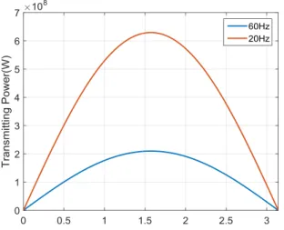
In (1), the total impedance of cables is proportional to the power system frequency and expressed by 2πfL where L is the total inductance over the cables. Therefore, to increase the power transmission capability, the power system frequency can be reduced. LFAC power transmission system is based on the concept of using low frequency transmission. When the power system frequency is 20 Hz, the power transmission capability can be expressed by (4). The power transmission capability at 20 Hz is almost 3 times of the power transmission at 60 Hz transmission because the total impedance of power system is reduced to 1/3 of the 60 Hz system. Fig. 1 shows transmission power vs. transmission angle variations.
sin 2 fL
V
p V
s r(2)
L V
p V
s r60
max(60Hz)
2 (3)
max(60Hz)
max(20Hz)
3
20
2 P
L V
p V
s r
(4)
B. Basic structures of LFAC and HVDC for a large offshore wind farm
A basic structure of LFAC power transmission system is shown in Fig. 2. The generated power at 20 Hz is transmitted through a three-core XLPE cable, and the transmitted 20 Hz power is converted to 60 Hz power by a frequency converter.
The frequency converter is located at the receiving terminal and interconnects the low frequency power system with a 60 Hz main grid. Several types of the frequency converter can be proposed; a cyclo-converter, a line-commutated converter with back to back configuration and a variable frequency transformer.
In LFAC power system for a wind farm, the frequency converter
station is only needed on a shore, but HVDC power system needs two converters in offshore and onshore stations as Fig. 2.
Moreover, the construction cost of converter stations increases dramatically as a distance from the shore.
The total LFAC power system is very similar to the conventional 60 Hz power system except the frequency converter which is a critical factor of increasing the total cost of the power system. However, the power transmission capability of LFAC can compensate for the high cost of the frequency converter.
III. ECONOMIC ASSESSMENTS OF LFAC AND HVDC TRANSMISSIONS
A. Proposed Configuration of a HVDC transmission system for a remote wind farm.
HVDC transmission system can have various configurations as converter types and transmission topologies.
As converter types, HVDC can be classified into CSI based HVDC and VSC based HVDC. CSI based HVDC has more conversion capability than VSC based HVDC, but CSI based HVDC generates reactive power and needs reactive power compensation. The VSC based HVDC can control real and reactive power respectively, and a VSC station for HVDC is known as its capability limit is 300 MW. As link topologies, there are three types: mono-polar, bipolar and back to back link topologies in HVDC system.
Generally, large offshore wind farms have a few hundreds of generated power and 50~150 miles far from the onshore grid.
Therefore, in this paper, the generated power of a large offshore wind farm is assumed 600 MW which is times of the known maximum capability of a VSC station, and the mono-polar HVDC system is adopted as a link topology because of the investment cost.
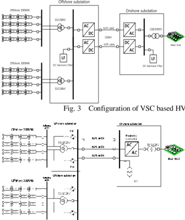
The detail configuration of VSC based HVDC power system is shown in Fig. 3. Wind turbines are connected to a collection point, and the generated power is accumulated and transmitted to an offshore substation. The offshore substation consists of two step-up transformers and two AC/DC converter stations which have 300 MW conversion capability respectively.
The converted DC power is transmitted to onshore substations through the XLPE cables. The onshore substation has two DC/AC converter stations and two step-up transformers. The converted AC power is transmitted to a main grid.
B. Configuration of a LFAC transmission system for a remote wind farm.
Fig. 1. Transmission power vs. Transmission angle variations (60 Hz vs. 20 Hz)
Frequency Converter
60Hz Transmission
AC to DC
Converter DC to AC
Converter
LFAC
HVDC
Low Freq.
Transmission
Low Freq.
Transmission 60Hz
Transmission Low Freq.
Transmission
TransmissionDC
Fig. 2. Basic structures of LFAC and HVDC for a large
offshore wind farm
Wind generation has low speed dynamics less than 20 Hz, and they have output converters respectively. Therefore, a frequency converter is not required at the offshore collecting point. Fig. 4 shows the proposed LFAC offshore wind farm configuration, which consists of offshore step-up transformers, reactive power compensators and an onshore frequency converter and step-up transformers. The three- core XPLE cables are used for transmission lines.
C. Investment cost comparison of HVDC and LFAC 1) Investment cost of HVDC
a) VSC Stations cost
HVDC converter stations consist of switching valves, transformers and filters, and its total investment cost is known as 0.15157 $ per W from ABB. Therefore, the cost of converter station for 600MW can be shown as (5)
station converter
C P 0 . 15187 2 2 15187 . 0 MW
300
(5)
122 .
91 m$
b) Cable cost
Cable cost is determined by a distance and nominal values (Power, voltage and current), and the transmission voltage and power losses are trade-offs. Cables for HVDC are cheaper than HVAC, and the cable costs of 220 MW, 350 MW and 500 MW are given in Table 1 [10]. The cable cost can be shown as (6) using a curve-fitting method.
08 . 0 0015 .
cable
0 P
C (6)
Where P is a nominal power [MW] of a cable, and 150 kV voltage is assumed. Its construction cost is 0.276 m$ per km.
2) Investment cost of LFAC
LFAC transmission system consists of transformer stations, offshore reactive power compensators, XLPE cables and a frequency converter. LFAC transmission can increase the power transmission capability rather than 60 Hz power system, but transformers can be saturated at a low frequency and the size of transformers should be larger than 60 Hz transformers. Contrary to transformers, reactive power compensation decreases because of low impedance of transmission lines.
a) Transformer cost
When a same nominal voltage of 60 Hz system is applied to LFAC system, the 60 Hz transformer can be saturated, so new configuration of transformers is needed. To estimate the cost of transformer, series-connected three 60 Hz transformers are assumed in this paper, which means that the applied voltage of transformer is assumed as 1/3 nominal voltage of 60 Hz transformer with the same current ratings to prevent the saturation of the 60 Hz transformer. The costs of 60 Hz transformers as capability are shown on Table 8, and represented as (7).
P f
C 60
0459 .
0
0.7516r
transforme
(7)
b) Reactive power compensation cost
The reactive power compensation is proportional to a distance and a transmission frequency, so its compensating power can decrease at a low frequency when a same distance is assumed. However, if a low frequency is used, the total impedance of the reactive power compensator decreases, but an inductance must be larger to compensate a same reactive power.
Therefore, the reactive power compensation cost can be calculated as Table 3 and represented as (8).
7516 . 0 SVC
0 . 153 P
C (8)
c) Cable cost [10]
Three-core XLPE cable can be used for LFAC transmission system. Table 4 shows the cable cost as nominal values (Power, Voltage and current). In LFAC transmission system, the cable nominal current decreases proportionally to a transmission frequency.
Fig. 3 Configuration of VSC based HVDC transmission system for a large offshore wind farm
Fig. 4. Configuration of HVDC transmission system for a remote wind farm
Onshore substation
Main Grid
DC Harmonic Filter
Offshore substation
XLPE cable
XLPE cable
LF
DC Harmonic Filter
LF
WT WT WT WT
WT WT WT WT
WT WT WT WT
WT WT WT WT
Offshore 300MW
WT WT WT WT
WT WT WT WT
WT WT WT WT
WT WT WT WT
Offshore 300MW
33/138KV
138/345KV
33/138kV
AC DC AC
DC
DC AC DC
AC
150kV
Table 1. Cable cost of HVDC Capacity
(MW) 220 350 500
C
cable pair(m$/km) 0.4192 0.6145 0.8398
Table 2. Cable cost of LFC
Capacity(MVA) 800 722 630 400 300 250 200 180 150 125 100 50 40 Ctransformer
(m$) 6.95 6.44 5.82 4.14 3.35 2.89 2.45 2.27 1.98 1.72 1.46 0.86 0.73
07 . 100 2
66 . exp 1 031219 . 0 294419 .
cable
0
kV
132
S
nC m$/km
rated rated
n
U I
S 3 (9)
27 . 100 2 66 . exp 1 016413 . 0 475163 .
cable
0
kV
132
S
nC m$/km
rated rated
n
U I
S 3 (10)
d) Frequency converting cost
A cyclo-converter, a back to back converter and a variable frequency transformer (VFT) can be a candidate for LFAC transmission system. However, the Cyclo-converter generates more harmonics and deteriorates the power quality, and the back to back converter has a complex structure as HVDC back to back system which construction cost is higher than the VFT. In this paper, the VFT is selected for converting power frequency because the VFT is very reliable as well as an economical solution. Moreover, the VFT has a simple structure which consists of a wound rotor induction motor and a driving motor, so it has advantages of easy maintenances and fault-tolerant capability. The main component of the VFT is a wound rotor induction motor, and it is very difficult to estimate its price because the exact price of hundreds MW induction motor is not open and some companies think the price information as secrets.
So, its cost can be estimated normally as three times of a same capacity transformer cost, just rough estimation and includes the prices of driving motors, circuits, capacitor bank, switch gears and electrical controller.
e) Switching gear cost
Switching gears can be estimated as voltage levels as shown in Table 5.
0496 . 0 0009
.
gear
0
sw
U
rated
C (11)
D. Economic comparison of LFAC and HVDC
The economic comparison and assessments of LFAC and HVDC transmissions for large offshore wind farms are presented. The economic assessment of two different transmission technologies are analyzed and compared in terms of wind farm’s capacities (600 MW and 900 MW) and distances (from 25 km to 100 km) from the onshore substation. Based on the cost information, the economical investment of LFAC for the transmission system of offshore wind farms can be estimated to Table 6. Fig. 5 and 6 show the economical comparison of LFAC and HVDC transmission systems for a remote wind farm as the power transmission capacities and distances from the onshore substation. Approximately, 110 km of distances from the onshore grid is the crossover point between HVDC and LFAC for the 600 MW wind farm, and 60 km is the crossover point for the 900 MW wind farm.
IV. CONCLUSIONS
In this paper economic assessments of LFAC and HVDC transmission systems for a large remote wind farm are presented.
The proposed power systems are analyzed and compared as 600 MW and 900 MW power transmissions with the distance range from 25 km and 200 km. The result shows that LFAC transmission system has more economical benefits than HVDC up to about 60 km for the 600 MW wind farm and 110 km for the 900 MW wind farm. However, these comparisons have no considerations about maintenances and reliability cost estimations, and their layouts cannot be exactly optimal configurations which can make a great impact on cost estimations. To estimate the overall cost of LFAC more exactly, Table 3. Reactive power compensation cost of LFAC
MVA Distance
Voltage 50 km 100 km 150 km 200 km 250 km 300 km 132kV 32.5 65 97.5 130 162.5 195
220kV 71 142 213 284 355
400kV 226 452 678 904
Table 4. Cable cost of LFAC
Voltage(kV) 132 220 400
Current(A) 1055 1055 1323
Section(mm2) 1000 1000 1200
Table 5. Switching gear cost of LFAC
U
rated(kV) 33 132 220 400
Cost(m$) 0.08004 0.17112 0.25254 0.41814 Table 6. Economical comparison of LFAC and HVDC
HVDC Cost (m$) LFAC (m$)
600 MW 900 MW 600 MW 900 MW
25 km 213.9 316.2 25 km 159.08 250.33 50 km 245.5 359.1 50 km 216.02 326.42 100 km 308.7 444.8 100 km 329.35 550.15 150 km 371.9 530.5 150 km 442.33 773.53
Fig. 5. Economic assessments of HVDC and LFAC (600 MW)
Fig. 6. Economic assessments of HVDC and LFAC (900 MW)
0.0 500.0 1000.0 1500.0 2000.0 2500.0
25km 50km 100km 150km 200km
HVDC HVAC LFAC
0 200 400 600 800 1000 1200
25km 50km 100km 150km 200km
HVDC HVAC LFAC