1. 서론
등속조인트는 종감속에 나온 구동력을 구동바퀴까지 각의 변화와 길이의 변화를 주어 구동력을 전달하며 주
로 FF(전륜 구동)방식, RR(후륜 구동)방식, 4DW(4륜 구 동)방식에서 많이 사용하고 축은 많은 힘을 받고 각의변 화가 크므로 고정형 등속 조인트를 사용하고, 종감속기 어 쪽에는 허용 각도가 작지만 축 방향으로 신축 가능한
자동차 등속 조인트 샤프트 길이에 따른 내구성 해석을 통한 융합연구
최계광1, 조재웅2*
1공주대학교 금형설계공학과, 2공주대학교 기계자동차공학부
A Convergence Study through Durability Analysis due to the Shaft Length of Automotive Constant Velocity Joint
Gye-Gwang Choi
1, Jae-Ung Cho
2*1
Department of Metal Mold Design Engineering, Kongju national University
2
Division of Mechanical & Automotive Engineering, Kongju National University
요 약 자동차의 구동방식은 전륜구동, 후륜구동, 4륜구동의 방식이 있다. 구동방식에서 운전자가 원하는 방향으로 전환하 는 것과 바퀴에 동력을 전달하여 구동하는 두 가지의 역할을 수행하는데 있어 가장 중요한 부품이 등속 조인트이다. 도로상 에서 주행 시에는 노면의 상태에 따라서 동력을 전달하는 부품들에 충격이 가해질 수 있다. 본 연구에서는 각각 샤프트의 길이가 다른 3개의 등속 조인트 각 모델들은 CATIA로 모델링하였고 ANSYS를 이용하여 구조 및 피로해석을 수행하였다.
본 연구 결과로는 Model 2가 다른 모델 대비 뛰어난 내구성을 가짐을 알 수 있었다. 이러한 결과를 이용하여 충격에 대한 내구성을 가지는 등속 조인트 설계를 할 때에 유용한 자료가 될 것이라고 사료되며, 등속 조인트의 디자인을 융합기술에 접목하여 미적 감각을 나타낼 수 있다.
주제어 : 등속 조인트, 전륜 구동, 후륜 구동, 4륜 구동, 구조 해석, 피로 해석, 융합 연구
Abstract
The driving methods of car are front wheel drive, rear wheel drive and four wheel drive. At driving methods, constant velocity joint is the most important part at carrying out two functions for converting to the direction which the driver wants and transferring the power to wheels. At driving on the road, the impact can be applied to the parts transmitting power according to the state of road surface. In this study, each models of three constant velocity joints whose shaft length are different respectively were modelled with CATIA and the structural and fatigue analyses were carried out by using ANSYS. This study result is thought to be the useful material at designing the constant velocity joint with the durability against impact. And it is possible to be grafted onto the convergence technique at the design of constant velocity joint and show the esthetic sense.Key Words :
Constant velocity joint, Front wheel drive, Rear wheel drive, Four wheel drive, Structural analysis, Fatigue analysis, Convergence study*Corresponding Author : Jae-Ung Cho ([email protected]) Received June 12, 2018
Accepted August 13, 2018
Revised July 13, 2018 Published August 28, 2018
슬립형 등속 조인트가 사용되는 것이 일반적이다. 본 연 구를 통해 모델링 및 해석을 하여 최적화된 샤프트의 길 이를 찾아내고 무게 또한 경량화 되도록 하고 자동차의 성능에도 영향을 어떻게 주는지에 대해서도 중점을 두었 다. 이를 통하여 3가지의 형상의 등속 조인트를 CATIA 로 모델링을 하였고, ANSYS로 구조 및 피로해석을 통하 여 등속 조인트의 내구성을 검토할 수 있어 설계에 활용 을 할 수 있으며, 이러한 해석결과를 바탕으로 등속조인 트의 설계에 응용하여 이번 연구에서 축적된 설계인자를 새로운 설계품에 융합하여 미적인 감각을 나타낼 수 있 다[1-7].
2. 본론
2.1 연구 모델
본 연구 모델은 자동차의 등속 조인트를 모델링을 하 였고, Fig. 1에서 보면 Model 1, 2, 3의 순으로 샤프트의 길이가 증가함에 따라서 모델링을 하였으며, 샤프트의 좌우로 고정형 등속조인트와 슬립형 등속 조인트를 모델 링 하였다.
(a) Model 1
(b) Model 2
(c) Model 3
Fig. 1. Analysis models2.2 해석 경계조건
해석 경계 조건으로는 2가지를 부여하여 진행하였다.
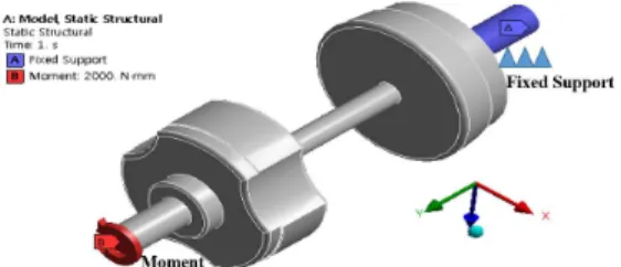
샤프트 길이 변화에 따른 변형에 대한 해석을 진행하기 위해 Fig. 2의 그림은 Model 1의 경계조건으로 Model 2, 3도 동일하며 경계조건은 한 바퀴에 걸리는 힘은 고정형
등속 조인트 쪽에서 2000N으로 정하고 접동형 등속 조인 트 쪽에는 바퀴에 의해 고정됨을 가정하였다.
Fig. 2. Analysis conditions of models
3. 해석 결과
3.1 구조해석
Fig. 3은 3개의 모델에 대한 Total deformation의 등고 선을 나타낸 그림이고, Fig.4는 3개의 모델에 대하여 Equivalent Stress의 등고선을 나타낸 그림이다. Model 1 의 샤프트 부분에 6.6652X10⁻³mm의 변형이 일어났고 최 대 0.76524MPa의 응력이 발생하였다. Model 2의 샤프트 부분에 1.3132X10⁻²mm의 변형이 일어났고 최대 0.76176MPa의 응력이 발생하였다. Model 3의 샤프트 부 분에 1.9656X10⁻²mm의 변형이 일어났고 최대 0.74517MPa의 응력이 발생하였다[8-12].
(a) Total deformation of model 1
(b) Total deformation of model 2
(c) Total deformation of model 3
Fig. 3. Total deformation of models(a) Equivalent stress of model 1
(b) Equivalent stress of model 2
(c) Equivalent stress of model 3
Fig. 4. Equivalent stress of models3.2 피로해석
Fig. 6와 Fig. 7은 Model 1에 대한 피로 하중의 내역들 로서 'SAE bracket history', 'SAE transmission' 및 'Sample history'에 대한 lif와 damage의 등고선을 나타 낸 값이다. Fig. 6에서 life의 값은 ‘SAE bracket history’
가 최소 4.8614, ‘SAE transmission’가 최소 39.195,
‘Sample history’가 최소 1046.7 으로 해석 되었으며, Fig.
5에서 damage의 값은 ‘SAE bracket history’가 최대
2.057×10⁸, ‘SAE transmission’가 최대 2.5514×10⁷,
‘Sample history’가 최대 9.5534×10⁵ 으로 해석되었다.
(a) SAE bracket history
(b) SAE transmission
(c) Sample history
Fig. 6. Fatigue life contour of model 1(a) SAE bracket history
(b) SAE transmission
(c) Sample history
Fig. 7. Fatigue damage contour of model 1
Fig. 8과 Fig. 9는 Model 2에 대한 피로 하중의 내역들 로서 'SAE bracket history', 'SAE transmission' 및 'Sample history'에 대한 lif와 damage의 등고선을 나타 낸 값이다. Fig. 8에서 life의 값은 ‘SAE bracket history’
가 최소 4.9319, ‘SAE transmission’가 최소 39.763,
‘Sample history’가 최소 1061.5 으로 해석 되었으며, Fig.
9에서 damage의 값은 ‘SAE bracket history’가 최대 2.0276×10⁸, ‘SAE transmission’가 최대 2.5149×10⁷,
‘Sample history’가 최대 9.4205×10⁵ 으로 해석되었다.
(a) SAE bracket history
(b) SAE transmission
(c) Sample history
Fig. 8. Fatigue life contour of model 2(a) SAE bracket history
(b) SAE transmission
(c) Sample history
Fig. 9. Fatigue damage contour of model 2
Fig. 10과 Fig. 11은 Model 3에 대한 피로 하중의 내역 들로서 'SAE bracket history','SAE transmission' 및 'Sample history'에 대한 lif와 damage의 등고선을 나타 낸 값이다. Fig. 8에서 life의 값은 ‘SAE bracket history’
가 최소 5.2899, ‘SAE transmission’가 최소 42.646,
‘Sample history’가 최소 1139.1 으로 해석 되었으며, Fig.
11에서 damage의 값은 ‘SAE bracket history’가 최대 1.8904×10⁸, ‘SAE transmission’가 최대 2.3449×10⁷,
‘Sample history’가 최대 8.779×10⁵ 으로 해석되었다.
(a) SAE bracket history
(b) SAE transmission
(c) Sample history
Fig. 10. Fatigue life contour of model 3(a) SAE bracket history
(b) SAE transmission
(c) Sample history
Fig. 11. Fatigue damage contour of model 2
3개 모델의 길이변화에 대한 피로해석 결과 ‘SAE
bracket history’의 피로하중에서의 수명은 최소 5.2899인 Model 3이 가장 길고 ‘SAE transmission’의 피로하중에 서의 수명은 최소 42.646인 Model 3이 가장 길고 ‘Sample history’의 피로하중에서의 수명은 최소 1139.1인 Model 3이 가장 긴 것을 알 수 있다. ‘SAE bracket history’의 피 로하중에서의 손상은 최대 2.057×10⁸ 인 Model 1이 가장 많은 것으로 나타났었고, ‘SAE transmission’의 피로하중 에서의 손상은 최대 2.5514×10⁷인 Model 1이 가장 많고
‘Sample history’의 피로하중에서의 손상은 최대 9.5534×10⁵인 Model 1이 가장 손상을 많이 입었다 [13-15].
3. 결 과
등속 조인트는 엔진의 구동력을 최종적으로 바퀴로 전달해주는 것이기 때문에, 고장 시 차량의 구동이 되지 않기 때문에 견고 하여야합니다. 하지만, 자동차는 경량 을 무시할 수 없으므로 강도는 최대한으로 끌어 올리는 구조로 하면서 경량화 또한 할 수 있는 구조로 설계 되어 야한다.
1. 길이변화에 따른 구조해석 결과 가장 짧은 Model1 이 가장 적합하지만, 샤프트 길이가 너무 짧게 되면 차륜거리가 짧아져 차량의 안정성에 나쁜 영향을 미치기 때문에 가장 짧은 Model 1보다는 Model 2 가 가장 적합하다.
2. 피로해석 결과 수명은 모든 피로하중 조건에서 Model 3이 가장 길었으며 손상은 모든 피로하중조 건에서 Model 1이 가장 손상이 많았다.
3. 구조 내구성인 면에 있어서, 최적화되어 있는 Model 2의 해석결과를 바탕으로 설계에 응용하여 타 모델 대비 더 뛰어난 내구성을 지닌 등속조인트 설계요소를 축적할 수 있었고 이를 융합 기술에 적 용하여 미적인 감각을 나타낼 수 있다.
REFERENCES
[1] M. J. Kang & J. U. Cho. (2014). A Study on Structural Durability due to the Configuration of Ripper at Excavator. Journal of the Korea Convergence Society,
5(2), 13-18.
[2] G. W. Hwang & J. U. Cho. (2017). Convergence Study on Durability Improvement due to Radius of Arch Type at CFRP Structure with Stacking Angle. Journal of the
Korea Convergence Society, 8(7), 219-224.
[3] J. W. Park. (2017). Structural Analysis of a Tractor Cabin Considering Structure Production Error. Journal of
the Korea Convergence Society, 8(5), 155-160.
[4] J. I. Lee. (2017). The Convergence Design for Stiffness and Structure Advancement of Automotive Body.
Journal of the Korea Convergence Society, 8(4),
189-197.[5] J. U. Cho. (2015). Study on Convergence Technique through Strength Analysis of Stabilizer Link by Type.
Journal of the Korea Convergence Society, 6(1), 57-63.
[6] J. U. Cho. (2015). Study on Convergence Technique through Structural Analysis on the Axle of Railway Vehicle. Journal of the Korea Convergence Society,
6(1), 93-101.
[7] J. W. Park & E. D. Kim & J. U. Cho. (2018). Analysis Study on Influence that the Center Hole Notch of CFRP with Laminated Structure Affects. Journal of the Korea
Convergence Society, 9(2), 323-329.
[8] J. H. Lee & J. U. Cho. (2015). Study on the Convergent Life Evaluation due to the Bumper Configuration of Multipurpose Vehicle.
Journal of the Korea Convergence Society, 6(5), 85-90.
[9] J. H. Lee & J. U. Cho. (2015). Study on Convergence Technique through Structural Analysis due to The Configuration of Door Hinge. Journal of the Korea
Convergence Society, 6(3), 59-64.
[10] K. W. Kang (2014). Vibration Fatigue Analysis of Spot Welded Component considering Change of Stiffness due to Fatigue Damage. Journal of the Korea Convergence
Society, 5(1), 1-8.
[11] J. U. Cho. (2014). A Durability Study through the Fatigue Analysis on the Emblem for Car. Journal of the
Korea Convergence Society, 5(4), 39-47.
[12] M. S. Koh. & S. K. Kwon & S. Lee. (2015). A Study for the Dynamic Characteristics and Correlation with Test Result of Gantry Robot based on Finite Element Analysis. Journal of Digital Convergence, 13(1), 269-274.
[13] W. B. Lee. & W. Y. Hao. & B. P. Kyung. & S. H. Ryu.
Dismantling Simulation of Nuclear Reactor Using Partial Mesh Cutting Method for 3D Model. Journal of Digital
Convergence, 13(4), 303-310.
[14] J. H. Hyeon. & Y. H. Moon. & S. W. Ha. Development of Automation Software for Corner Radius Analysis of
Composite Laminated Structure. Journal of Convergence
for Information Technology, 8(3). 107-114.
[15] J. L. Cui. & M. H. Chey & S. I. Kim. Seismic Performance of Urban Structures with Various Horizontal Irregularities using Equivalent Static Analysis. Journal of Convergence for Information
Technology, 6(1). 25-32.
최 계 광(Gye-Gwang Choi) [정회원]
▪1993년 2월: Pusan University of Technology Metalmold Engineering (공학사)
▪1995년 8월 : 국민대학교 대학원 기계설계학과 (공학석사)
▪2005년 2월 : 국민대학교 대학원 기계설계학과 (공학박사)
▪2005년 8월 : (주) 현대배관 기술부장
▪2006년 5월 ~ 현재 : 공주대학교 금형설계공학과 부교수
▪관심분야 : 3D CAD, CAM Programing
▪E-Mail : [email protected]
조 재 웅(Jae-Ung Cho) [종신회원]
▪1980년 2월 : 인하대학교 기계공 학과 (공학사)
▪1982년 2월 : 인하대학교 기계공 학과 (공학석사)
▪1986년 8월 : 인하대학교 기계공 학과 (공학박사)
▪1988년 3월 ~ 현재 : 공주대학교 기계·자동차공학부 교수
▪관심분야 : 기계 및 자동차 부품 설계 및 내구성 평가, 피로 또는 충돌 시 동적 해석
▪E-Mail : [email protected]