Measurement of Heat Transfer Coefficient in Dimpled Channel: Effect of Dimple Arrangement and Channel Height
K. S. Lee, S. M. Shin, and S. D. Park
Graduate student, School of Aerospace and Mechanical Engineering, Korea Aerospace University
J. S. Kwak*
Corresponding author, School of Aerospace and Mechanical Engineering, Korea Aerospace University 200-1 Hwajoen-Dong, Deogyang-Gu, Goyang-City, 417-791, Korea
J. S. Kang
KHP Development Division, Korea Aerospace Research Institute 45 Eoeun-Dong, Yuseong-Gu, Dajeon, Korea
Keywords: turbine heat transfer, turbine blade cooling, dimple, transient liquid crystal technique Abstract
In this paper, heat transfer coefficients were measured in a channel with one side dimpled surface.
The sphere type dimples were fabricated and the diameter and depth of dimple was 16mm and 4mm, respectively. Two channel heights of about 0.6 and 1.2 time of the dimple diameter, two dimple configuration were tested. The Reynolds numbers based on the channel hydraulic diameter was varied from 30000 to 50000. The improved hue detection based transient liquid crystal technique was used in the heat transfer measurement. Heat transfer measurement results showed that high heat transfer was induced downstream of dimples due to flow reattachment. Due to the flow recirculation on the upstream side in the dimple, the heat transfer coefficient was very low. As the Reynolds increased, the overall heat transfer coefficients also increased.
With same dimple arrangement, the heat transfer coefficients and the thermal performance factor were higher for the lower channel height. As the distance between dimples became smaller, the overall heat transfer coefficient and the thermal performance factor were increased.
Introduction
It is known that the efficiency and power output of the gas turbine engine increase as the turbine inlet temperature increases and the operating temperature of modern gas turbines is beyond the permissible temperature of a turbine blade material. In this condition, the sophisticate cooling system is required in order to maintain durability and required lifetime of the turbine blades.
Blade cooling system could be selected by considering degree of heat transfer augmentation, pressure drop through the cooling channel, and manufacturing simplicity. Based on the previous
researchers, it is known that the dimpled surface increases heat transfer with lower pressure drop compared to rib turbulator cooling technique which is widely used in the gas turbine blade. Furthermore the surface with dimple is easy to be fabricated. Thus, heat transfer augmenting technique using dimple has been tried as a blade cooling system in the gas turbine.
Dimple fabricated on the surface increases heat transfer because it induces flow separation, reattachment, and vortices. Khalatov et al.1) visualized flow near dimple by dye injection. Mahmood et al.2) used infrared thermography and presented flow visualization, time-averaged total pressure and streamwise velocity, and spatially-resolved local Nusselt numbers near dimple. Mahmood and Ligrani3) presented the influences of dimples on flow structure and heat transfer on different channel aspect ratio, different inlet air-to-local wall temperature ratio, and Reynolds number. Burgress and Ligrani4) investigated friction factors and Nusselt number based on dimple depth. Moon and Lau5) examined the effect of dimple geometry on the convective heat transfer and pressure drop in a square channel with an array of concave or cylindrical dimples. Moon et al.6) measured heat transfer coefficients in the four different channel heights, and friction factors using static pressure taps.
Ligrani et al.7) investigated the effect of dimple depth and inlet turbulence intensity on the Nusselt number and friction factors. Chyu et al.8) studied local heat transfer distribution on the surfaces with hemispheric and tear-drop shapes of concavities using a transient liquid crystal imaging system. Ligrani et al.9) experimented in a channel with a dimpled surface on one wall, both with and without protrusions on the opposite wall, while Borisov et al.10) studied in a channel with dimple concavities on both sides.
Most previous literatures presented the averaged Nusselt number or local Nusselt number distribution with low resolution. In this paper, in order to
investigate the detailed heat transfer augmentation by dimple, the improved transient liquid crystal technique was used to measure the detailed local heat transfer coefficient distribution in and near the dimple fabricated on a flat surface. The quality of measured heat transfer coefficient by the transient liquid crystal technique was improved by time-hue curve fitting method and the analytical solution for the varying mainstream temperature condition. The presented measurement results will clearly show high and low heat transfer region by the dimple induced flow phenomena.
Experiment set up
Test facility consists of a venturi flow meter with a differential pressure transmitter (Rosemount, 250in H2O), a blower (pmax=4800mmH2O, Qmax= 9.8m3/min), an electrical heater (12kW), and two pneumatic valves. Figure 1 shows the schematic of test facility. Test section was made of 10mm transparent polycarbonate plate. The flow rate is measured by a venturi flow meter and calculated by Eq. (1).11)
4 d
4
C 1 2 p
Q d
1 4
= ε π Δ
− β ρ (1)
Heated air is bypassed until the air temperature reaches preset value. After the air temperature becomes predetermined value, air is diverted to the test section by pneumatic valves. Thermocouples or pressure taps were installed at the beginning and end of arrayed dimples to measure mainstream temperature and pressure drop through the dimpled region. Black paint and liquid crystals (35C1W, Hallcrest) with bandwidth of 1℃ were sprayed on the heat transfer measurement planes and digital CCD camera and incandescent lamps were installed above the test section. During the heat transfer measurement, the color change of liquid crystals was stored in a computer through IEEE1394 cable in a rate of 30 frames per second, DV format AVI file. From the every pixel of each frame of the AVI file, RGB(red, green, and blue) values are calculated and converted to 8 bit HSI(hue, saturation, and intensity). The hue history on each pixel was curve-fitted in order to calculate the transient time between test start and the time at which the hue value becomes preset value. All
image process was conducted by Matlab based image processing program developed by authors. By using time-hue curve fitting method, the unstable hue behavior in low intensity condition and noise effect on hue by camera capturing system can be reduced and more accurate transient time can be evaluated.
Detailed image processing procedure was described by Shin and Kwak12).
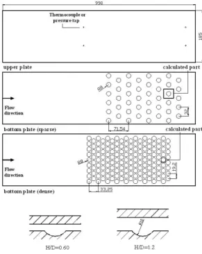
During the transient tests, the change of mainstream temperature was measured by 4 T-type thermocouples and recorded by data acquisition device (Agilent, 34970A). Figure 2 presents configuration of test section. The diameter and depth of the dimple were 16mm and 4mm, respectively. The channel height to the diameter of the dimple was 0.6 and 1.2, and two dimple arrangements shown in Fig. 2 were tested.
Measurement theory
In the transient liquid crystal technique, the test surface is assumed as a semi-infinite solid wall with convective boundary condition. If the sudden change in mainstream temperature or velocity is applied to the test section, the surface temperature changes with time and the heat transfer coefficient can be calculated by utilizing time between the initial temperature and the preset surface temperature. Basic equation, initial, and boundary condition are as followings;
2
w 2 w p
T T
k c
x t
∂ ∂
= ρ ∂
∂ (2)
at t=0, T=Ti (3)
heater
Blower
Venturi flow meter Pneumatic
valves Plenum
Fig. 1 Schematic of test facility (not to scale)
Fig. 2 Configuration of test section
w w m
at x 0, k T h(T T ) t
= − ∂ = −
∂ (4)
as x→ ∞, T=Ti (5) If mainstream temperature varies with time, which commonly occurs in internal heat transfer tests, temperature variations of the mainstream can be expressed as shown in Eq. (6).13)
N n 1
m m i n
n 1
T T a t
(n)
−
=
θ = − =
∑
Γ (6)Where, N=n+1
n: order of the polynomial Γ(n): Gamma function
an: coefficients of the order-n polynomial Temperature variation on the surface (x=0) can be expressed as Eq. (7).
( )
[ ]
( )
2 p
w w i
N n n m
n 2(m 1)
n 1 m 1 p
t 2(n 1) p p
n i 1
n 1 n i 2
2i 1 i 1 p
p
T T
1 t
a (n m)!
1 e erfc t
1 2 t
1 3 5 7 2(n i) 1
where h
k
−
= = −
β
−
− − − −
= −
θ = −
= ⎡⎢⎣ β −
− β
β
− β ⋅ ⋅ ⋅ ⋅⋅⋅⋅⋅⋅ − − π ⎦⎤⎥
β = α
∑ ∑
∑
(7)
α : thermal diffusivity of the test section k: thermal conductivity of the test section t: transient time
h: heat transfer coefficient
Once the time (t) from initial temperature (T )i to pre-defined temperature (T )w is determined, heat transfer coefficient can be calculated by Eq. (7).
Mainstream temperature (T )m is curve-fitted using averaged temperature measured by T-type thermocouples installed at beginning and end of dimple fabricated region. The mainstream temperature for the heat transfer calculation at each pixel was calculated based on the distance between the thermocouples and the location of each pixel.
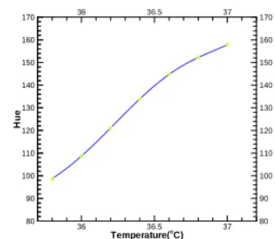
Surface temperature (T )w is obtained from pre- operated hue-temperature calibration. For the hue- temperature calibration, copper plate was attached on the hot side of thermoelectric element using high conductive glue. A T-type thermocouple was
instrumented on the copper plate and 1℃ bandwidth liquid crystals (35C1W, Hallcrest) was sprayed on the copper plate after black paint was applied on. By changing the temperature of the copper plate by 0.2℃
step, the color of liquid crystals coated surface was recorded and hue value was calculated. Figure 3 shows the relation between the calculated hue and the temperature obtained by thermocouple couples.
Augmentation of heat transfer by dimpled surface accompanies pressure drop. Thus, the heat transfer augmentation should be compared with the pressure drop in order to evaluate the thermal performance of heat transfer enhancing method. In this study, thermal performance factor defined by Eq. (8) was used.
( )
h h
D D ,0
1/ 3 0
Nu / Nu TP
f / f
= (8)
In Eq. (8), f0 is the friction factor for fully developed turbulent flow in the smooth tube, f is the Darcy friction factor calculated from pressure measurement,
D ,0h
Nu is Nusselt number for fully developed turbulent flow in smooth tubes with the same hydraulic diameter, and
Dh
Nu is measured Nusselt number. f is defined as Eq. (9).
h 2 m
( p / x) D
f u / 2
− Δ Δ
= ρ (9)
In Eq. (9), pressure drop was measured by total four pressure taps as shown in Fig. 2. f0 is calculated by Eq. (10) 14).
h
2
0 D
f =⎡⎣0.79 ln(Re ) 1.64− ⎤⎦− (10)
for h
6
3000 < ReD < ×5 10
The average and local Nusselt number is defined as Eq. (11) and
D ,0h
Nu can be calculated by Eq. (12) 14), respectively.
Temperature(oC)
Hue
36 36
36.5 36.5
37 37
80 80
90 90
100 100
110 110
120 120
130 130
140 140
150 150
160 160
170 170
Fig. 3 Relation between temperatureand hue
h
h D
m
Nu hD
= k (11)
h h
0 D
D ,0 1/ 2 2 / 3
0
(f / 8)(Re 1000) Pr Nu
[1 12.7(f / 8) (Pr 1)]
= −
+ − (12)
for 0.5 < Pr<2000
h
6
3000 < ReD < ×5 10
Results and Discussions
Various flow phenomena are induced by dimple as shown in Figure 4.15) The boundary layer of mainstream is separate by dimple and recirculation zone is created in upstream side of dimple. The separated mainstream flow reattaches in downstream side of dimple surface and the reattached flow forms twin vortex. As the flow comes out of the dimple, flow reattaches again on downstream of dimple.1), 2), 9)
These complex flow phenomena induce high and low heat transfer in and near dimple.
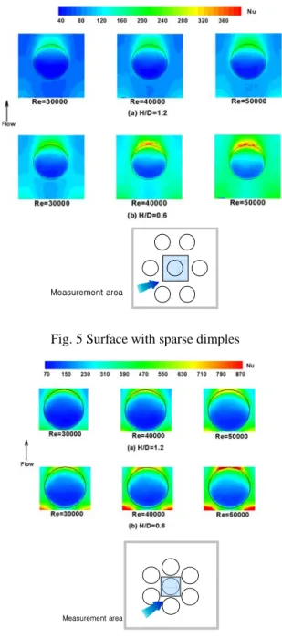
Figure 5 shows the distribution of Nusselt number for sparsely distributed dimples. Reynolds numbers shown in Fig. 5 are based on averaged mainstream flow velocity and channel hydraulic diameter. Results show that the Nusselt number increases as the Reynolds number increases. Also, the Nusselt numbers for the lower channel height cases are higher than those for the higher channel height cases. For same Reynolds number, the mainstream velocity is higher for lower channel height cases, which results in higher Nusselt number for lower channel height cases.
Also, higher Nusselt number for lower channel height cases is partly caused by the enhanced flow disturbance for lower channel height case. As the ratio of channel height to dimple diameter decreases, the flow can be more disturbed by the dimple, which causes higher Nusselt number. Figure 5 also clearly show the high and low heat transfer regions in and downstream of dimple. Due to the flow recirculation, the heat transfer coefficients in upstream of dimple are low. The heat transfer coefficients in downstream dimple are higher because of the flow reattachment.
High heat transfer coefficients along dimple edge can be seen at about 2/3 region from the dimple upstream,
and it is insisted that the high heat transfer region along rim is caused by the twin vortex and flow reattachment. As the flow comes out from the dimple, the flow reattaches again on the surface and causes high heat transfer region at downstream of dimple.
Figure 6 presents the distribution of Nusselt number for densely distributed dimples. The overall distribution of Nusselt number is similar to sparsely distributed dimple case (Fig. 5). For same Reynolds number and channel height, the Nusselt number for densely distributed case is higher than that for the sparsely distributed dimple case. As the distance between dimples is reduced, more flow disturbance is caused by dimples, which results in increase of heat transfer.
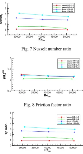
Figure 7 shows the averaged Nusselt number on dimpled surface compared to a smooth tube with
Measurement area
Fig. 6 Surface with dense dimples
Measurement area
Fig. 5 Surface with sparse dimples Fig. 4 Dimple induced flow phenomena
same hydraulic diameter. Generally, Nusselt number ratio decreases as the Reynolds number increases. For same Reynolds number, lower channel height case shows higher Nusselt number ratio and densely distributed dimples induces higher Nusselt number ratio. Thus, the highest Nusselt number ratio is obtained for densely distributed dimple with low channel height case.
Figure 8 presents the friction factor ratio compared to a smooth tube with same hydraulic diameter.
Generally, the friction factor ratio decreases as the Reynolds number increases. Actual pressure drop is higher for the higher Reynolds number case, but the difference in the friction factor ratio was not high.
Figure 9 shows the thermal performance factor.
The thermal performance factor generally decreases as the Reynolds number increases, however, the amount of change is not great. The thermal performance factor more depends on the arrangement of dimple or channel height. Thus, the thermal performance of dimpled surface can be optimized by changing the channel height to dimple diameter ratio or the arrangement of dimples. In this study, one dimple depth was tested, but it is expected that the depth of dimple is one of important factor of heat transfer augmentation with dimpled surface. The optimization of dimple configuration and arrangement will be next step of this study.
Conclusions
In this paper, the distribution of heat transfer coefficient on the dimpled surface was measured by the improved transient liquid crystal method. Two configurations of dimple were tested and for each configuration, channel height to dimple diameter ratio was 0.6 and 1.2, and depth of dimple is 1/4 of the dimple diameter.
Results showed that the heat transfer coefficient in upstream of dimple was low because of flow recirculation and high heat transfer region was found in downstream of dimple due to flow reattachment.
The heat transfer coefficient increased as the Reynolds number increases and the lower channel height cases showed higher heat transfer coefficient.
Also, the heat transfer coefficient was higher for densely distributed dimple case. The thermal performance factor was generally larger than 1 and the highest thermal performance factor was over 3 for the lower channel height with densely distributed dimple case.
It was clearly shown that the configuration of dimple and channel height could be optimized in order to increase the thermal performance factor. The other possible performance factor such as depth or shape of dimple will be considered in following studies.
Acknowledgments
This study has been supported by the KARI under KHP Dual-Use Component Development Program funded by the MOCIE and the Korea Research Foundation Grant funded by the Korean Government (MOEHRD, Basic Research Promotion Fund) (KRF- 2007-331-D00068).
References
1) Khalatov, A., Byerley, A., Ochoa, and Seong-Ki, M.: Flow characteristics within and downstream of spherical and cylindrical dimple on a flat plate at low Reynolds numbers, 2004, ASME paper GT2004-53656.
2) Mahmood, G. I., Hill, M. L., Nelson, D. L., and Ligrani, P. M.: Local heat transfer and flow structure on and above a dimpled surface in a channel, 2000, ASME paper 2000-GT-230.
3) Mahmood, G. I. and Ligrani, P. M..: Heat transfer in a dimpled channel: combined influences of aspect ratio, temperature ratio, Reynolds number, and flow structure, 2002, International journal of heat and mass transfer, pp. 2011-2020.
4) Burgess, N. K. and Ligrani, P. M.: Effects of dimple depth on Nusset numbers and friction factors for internal cooling in a channel, 2004, ASME paper GT2004-54232.
5) Moon, S. W. and Lau, S. C.: Turbulent heat transfer measurements on a wall with concave and cylindrical dimples in a square channel, 2002, ASME paper GT-2002-30208.
ReDh
Tpratio
30000 35000 40000 45000 50000 0
1 2 3 4 5 6
sparse H/D=1.2 sparse H/D=0.6 dense H/D=1.2 dednse H/D=0.6
Fig. 9 Thermal performance ratio
ReDh (f/f0)1/3
30000 35000 40000 45000 50000 0.5
1 1.5 2
sparse H/D=1.2 sparse H/D=0.6 dense H/D=1.2 dense H/D=0.6
Fig. 8 Friction factor ratio
ReDh Nu/Nu0
30000 35000 40000 45000 50000 0
1 2 3 4 5 6
sparse H/D=1.2 sparse H/D=0.6 dense H/D=1.2 dense H/D=0.6
Fig. 7 Nusselt number ratio
6) Moon, H. K., O'Connell, T. and Glezer, B.:
Channel height effect on heat transfer and friction in a dimpled passage, 2000, Journal of Engineering for gas turbines and power, Vol.
122, pp. 307-313.
7) Ligrani, P. M.N Burgess, N. K. and Won, S. Y.:
Nusselt numbers and flow structure on and above a shallow dimpled surface within a channel including effects of inlet turbulence intensity level, 2004, ASME paper GT-2004-54231.
8) Chyu, M. K., Yu, Y., Ding, H., Downs, J. P., and Soechting, F. O.: Concavity enhanced heat transfer in an internal cooling passage, 1997, ASME paper 97-GT-437.
9) Ligrani, P. M., Mahmood, G. I., Harrison, j. l., Clayton, C. M., and Nelson, D. L.: Flow structure and local Nusselt number variations in a channel with dimples and protrusions on opposite walls, 2001, International journal of heat and mass transfer, pp. 4413-4425.
10) Borisov, I., Khalatov, A., and Kobzar, S.:
Comparison of thermo-hydraulic characteristics
for two types of dimpled surfaces, 2004, ASME paper GT2004-54204.
11) ISO: Measurement of fluid flow by means of pressure differential devices inserted in circular cross-section conduits running full-Part 4:
Venturi tubes, 2004, ISO 5167-4
12) Shin, S., Jeon, C. S., Kwak, J. S., and Jung Y.
W.: Improvement of accuracy in evaluating hue change time in the hue detection based transient liquid crystals technique, 2007, KSME, vol. 31, no. 11 pp.918-915.
13) Kwak, J. S. : Comparision of analytical and superposition solutions of the transient liquid crystal technique, accepted to be published in Journal of thermophyssics and Heat Transfer 14) Frank, P. I. and David, P. D.: Fundamentals of
heat and mass transfer, John Wiley & Sons Inc., New York, 2001, pp. 470-492
15) Griffith, T. S., Al-Hadhrami, L., and Han, J. C.:
Heat transfer in rotating rectangular cooling channels (AR=4) with dimples, 2002, ASME paper GT-2002-30220.