내열환경 단조공정에서 핸들링작업을 위한 유연 아암 그리퍼 설계에 관한 연구
A Study on Design of Flexible Gripper for Handling Working of the Forging Process in Heat Resisting
Environment
양준석1*, 구영목1, 조상영1, 원종범2, 원종대3, 한성현4
Jun-Seok Yang, Young-Mok Koo, Sang-Young Jo, Jong-Bum Won, Jong-Dae Won, Sung-Hyun Han
<Abstract>
Recently Manipulation capability is important for a robot. Interaction between a robot hand and objects can be properly controlled only is suitable sensors are available. Recently the tendency is to create robot hands more compact and high integrated sensors system, in order to increase the grasping capability and in order to reduce cabling through the finger, the palm and the arm. As a matter of fact, miniaturization and cabling harness represents a significant limitation to the design of small sized embedded sensor. Ongoing work is focusing on a flexible manipulation system, which consists of a dual flexible multi-fingered hand-arm system, and a dual active vision system.
Keywords : Hand Controller, Robot Hand, Grasping Control
1. *정회원, 교신저자, 경남대학교 첨단공학과 (E-mail: [email protected]) 2. 정회원, (주)SMEC, 대표
3. 정회원, (주)영창로보테크, 태표
4. 정회원, 경남대학교 기계공학부 교수 工博
1. *Dept. of Advanced Engineering, Kyungnam University.
2. SMEC Co., Ltd., CEO
3. Youngchang Robotech Co., Ltd., CEO
4. Prof., School of Mechanical Engineering, Kyungnam University, Ph. D.
1. INTRODUCTION
Recently Manipulation capability is important for a robot. Interaction between a robot hand and objects can be properly controlled only is suitable sensors are available. In particular, information about the forces applied at the contact, the contact location, other indirect measurements, e.g.
estimate of mass object, its inertia ellipsoid, or even non mechanical measurements, may play a crucial role to implement secure grasp and safe manipulation tasks. In the past two decades several robot hands and dexterous grippers have been developed.
The major goals have been on one hand that of studying and implement newer mechanical solutions in order to increase miniaturization and dexterity, and, on the other, to investigate manipulation models and control techniques. At mechanical level study on dextrous grippers has mainly focused on the actuation and kinematics aspects. With very few exceptions (e.g.
[1]-[2]), tendon actuated mechanisms, and their numerous variants, still represent an effective way to implement compact manipulators. Actuation of tendon based robot grippers poses various technical problems. Tendons coupling on one hand, friction and elasticity on the other, pose important problems for the control of tendon actuated mechanisms. However, the mechanical accuracy required to design a miniature (e.g. human sized) dextrous gripper, is by far less than an equivalent design based on gears or other stiff
transmission mechanism. Recently the tendency is to create robot hands more compact and high integrated sensors system, in order to increase the grasping capability and in order to reduce cabling through the finger, the palm and the arm. As a matter of fact, miniaturization and cabling harness represents a significant limitation to the design of small sized embedded sensor[3].
The major contribution of this paper is to present the design of a fully integrated tactile and 3-axis force sensor, with embedded electronics. The approach adopted has been that of using low cost components available off-the-shelf, and to pursue a highly modular sensor design.
The system is scalable and designed to be integrated on the supporting three-finger hand. In particular, two identical sensors are mounted on each finger, one for phalange. The structure of this paper is as follows. In section 2, the hand system design is described. Then, in section 3 the basics of the contact-sensing problem are discussed. The modular structure of the sensor is presented and detailed in sections 4. Conclusions & Result are finally discussed in section 5, 6.
2. HAND DESIGN
he mechanism of a flexible hand gripper requires the mass of the hand should be as low as possible. It is highly desirable that the hand weigh less than 1kg. Furthermore the
low mass of the finger mechanism is desirable not only to achieve flexible motion but also for stable control[4].
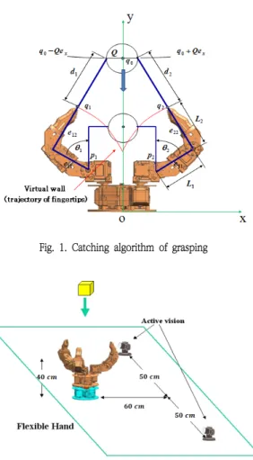
Our philosophy about dynamic manipulation is maximization of the power and minimization of the mechanism. In particular four factors are important: (1)light weight, (2) high speed and high acceleration, (3) accuracy, (4) possibilities of flexible grasping. Fig. 1 shows the mechanical design of the hand, and Fig. 2 shows a scene of the Gripper control. We used three fingers, which is the minimum number to achieve a stable grasp. Each of fingers has 4 degrees of freedom (D.O.F); the hand system has 10 D.O.F included 1 D.O.F on the hand link.
Note that the Joint 4 consists of the linear motor so that the finger tip can move as slide but other links just moving as rotate around a horizontal axis. In general a hand needs 10 D.O.F to move a target to any position and orientation. But our hand has 10 D.O.F so that the applications are very wide in the working environments, and the fingers are arranged so as to grasp the objects like circular and prismatic, etc. In order to achieve “lightning” high acceleration, we have developed a new actuator that allows a large current flow for a short time. Table 1 shows the specification for the actuator[5].
The finger has strain gauges at the joint 1 and joint 2 for force control. In addition a 6-axis force/torque sensor and a tactile sensor are mounted on each fingertip.
Motor type
Coreless DC Motors (Swiss MAXON
Motor) Operating Voltage [V] 15~20 Max. Holding torque
[Kgf.cm] 31.5
Max. Speed [sec/60deg] 0.15
Weight [g] 60
Size [mm] 35 x 30 x 34
Gear Ratio 190
Position Resolution 1024 Operating Angle [deg] 270
The flexible motion imposes a heavy load on the finger mechanism. For this reason a simple mechanism should be used for reduction gear, transmission, etc. In most traditional hand systems a wire-driven mechanism is used. But this is not suitable for a lightweight mechanism, because it is large and complicated[6].
In our hand a newly developed small harmonic drive gear and a high-power mini actuator are fitted in each finger link and all of these parts are hidden in the plastic case.
A harmonic drive gear has desirable properties for control such as no backlash and a high reduction rate.
The hand system consists of a camera at the center position as shown in Fig. 1 or can be added the dual vision system, as shown in Fig. 2. Following the purpose of this paper; we discus about the system set up in Fig. 2. the operating environment of control system[7].
Fig. 1. Catching algorithm of grasping
Fig. 2 The operating environment of control system
Early image processing is performed in order to achieve segmentation of the image, extraction of the target area, and computation of the image moments. From these data, the position of the target is computed; each vision sensor is mounted on an active vision.
2.1 Force Sensor Design
Manipulation control requires in general some sort of feedback which could provide
information about the interactions occurring during contact between the gripper and the grasped object. Assumptions must be made about the nature of the contact and, on the base of the selected contact models, it is possible to specify the nature of feedback required to properly control the interaction.
Detailed contact mechanics models are in general too complex to be taken into account in real-time control applications. In practice, simplified lumped parameter models are usually considered, [4]. In the soft finger model it is assumed that also a torque, aligned with the normal to the surfaces in contact, arises. The model equations for these models are:
îí ì
p
× c + q
= m
p
= f
(1)
Where p and q are the contact force and torque (for soft finger models only), c is the contact location, and f and m are the measured force and torque. Bicchi and Salisbury[4], proposed procedures for computing p and q on the base of the measurements f and m. However a precise geometric model of the pressure (the robot finger) is required, and, except the case of simple geometries, the method is computationally intensive and critical for real-time implementation[8].
A direct solution to the contact problem would be obviously possible if the contact location c would be directly measured.
Therefore the availability of a direct force measurement and of the contact location allows directly to solve the point contact problem.
At system level the goal is to develop to an integrated tactile/force sensors with embedded electronics to be placed on the phalanges of three fingers. The relevant problems considered have been: choice of appropriate force transducers, pressure transducers for contact measurements, integrated electronic design.
As a force sensor, we have used the integrated micro force sensor LPM 562. This force sensor provides precise, reliable force sensing performance in a compact commercial grade package. The force sensor operates on the principle that the resistance of silicon implanted piezoresistors will increase when the resistors flex under an applied force. The load is applied to a stainless steel plunger transmitting force to the silicon sensing element. The sensor packaging incorporates a modular construction and use of innovative elastomeric technology and engineered molded plastics which allow for load capacities of 4500 grams overload.
The device consists of three strain sensitive thick-film resistors. A force applied to the interface stick produces a change of resistivity. Proper arrangement of the resistors in three Wheatstone bridges, and a simple decoupling amplifier, allow obtaining three voltages proportional to the applied force
components. Digital potentiometers are used for self-calibration of the bridges and three instrument amplifiers provide appropriate signal conditioning before sampling.
The tactile transducer is a matrix of 64 electrodes covered by a layer of pressure sensitive conductive rubber (PCR Co. Ltd.).
The electrodes are etched on a flexible PCB substrate, in order to conform to a cylindrical surface. A thin elastic sheet covers the whole sensor and provides a mild preload useful to reduce noise. Pressure due to contacts produces changes of resistance among the electrodes. The geometry of the electrodes has been defined with the goal of limiting the spurious currents that may occur across the various electrodes, and interfere with measurement, as discussed in [7].
2.2. Tactile Data Processing
Tactile data are sampled by the on-board MCU, with 10 bit resolution. Preliminary tests show an actual sensor resolution of 8 bit/taxel. Each tactile image consists of 64 taxels.
During contact, a number of adjacent taxels are subject to pressure. The analog output of the tactile sensor allows to measure the distribution of pressure over all the transducer. Therefore, we propose to compute the contact centroid [4], as
åå åå
= =
= =
= N
i N
j ij N
i N
j
ij ij
x p
x p x C
1 1
1 1
) (
) ( . ˆ
(2)
where ˆC is the computed contact centroid, xij is the coordinate of the taxel and p(xij) the weight of this. As a matter of fact further geometric information about the distribution of the pressure during contact could be useful, although not directly relevant to point contact model solution. To this aim the pressure distribution is approximated as an ellipsoid, fig. 11, as follows:
åå åå
= =
= =
- -
= N
i N
j ij N
i N
j
ij T ij ij
x p
x p C x C x E
1 1
1 1
) (
) ( . ˆ) ˆ)(
(
(3)
Where E is a symmetric matrix who represent the ellipsoid. The approach used to compute and the associated approximate ellipsoid, is strongly based on the availability of an analog tactile sensor.
3. EXPERIMENT AND RESULTS
The main advantage of a multi-fingered hand is that it can grasp various objects by changing its shape. Several classifications of grasping have been proposed. In this proposal various grasps are classified into three large categories: a power grasp that passively resists arbitrary external forces exerted on the object, a precise grasp to manipulate the object, and an intermediate grasping which some fingers are used for a power grasp and the other fingers are used
for a precise grasp.
Catching is one of the most important tasks for dynamic manipulation. In this section catching is shown using our flexible hand with a visual feedback controller. We used a rubber ball with radius of 5cm as a target, and we dropped it from about 1.2m in height. The speed of the falling ball is about 5.9m/s just before it hits the ground.
From various experimental trials, we have decided on the catching strategy.
Fig. 3 shows the results of performance test for finger trajectory tracking.
The success rate was more than 90% and tolerance of position error of the target was about ±1.5cm from the center of the palm.
Several types of failure modes were observed. The direction of a bounced ball depends on the coefficient of friction and restitution. It is difficult to know the accurate values of these parameters, but the errors in their measurement may be ignored if the speed of the fingertip is fast enough.
(a) Result for sine wave input trajectory
(b) Result for the step input trajectory
Fig. 3. Result of performance test for finger trajectory tracking
4. CONCLUSION
An integrated force and tactile sensor with embedded electronics has been presented in a lightweight flexible hand with 10 D.O.F, and the associated visual feedback control.
The sensor consists of a three components commercial force sensor and of a custom matrix tactile sensor based pressure sensitive conductive rubber. The joint used of both tactile and force information allows the direct solution of the point contact problem. A technique to compute the contact centroid and a quadratic approximation of the pressure distribution during contact has been proposed. Ongoing work is focusing on a flexible manipulation system, which consists of a dual flexible multi-fingered hand-arm system, and a dual active vision system. In
the future this new hand-arm system will be used for multi tasks.
The need for a robotic hand that works in the real world is growing. And such a system should be able to adapt to changes in environment. We think that the concept of a flexible hand system with real-time control implementation will become an important issue in robotic research.
후 기
본 연구는 로봇비즈니스벨트조성사업의 일환으 로 수행되었음
참고문헌
[1] T. Asfour, K. Berns and R. Dillmann, “The Humanoid Robot ARMAR”, Proc. of the Second International Symposium on Humanoid Robots (HURO´99), October 8- 9, 1999, Tokyo, Japan
[2] T. Asfour, K. Berns, J. Schelling and R.
Dillmann, “Programming of Manipulation Tasks of the Humanoid Robot ARMAR”, The 9th International Conference on Advanced Robotics (ICAR'99), 25-27 October, Tokyo, Japan
[3] S. Toyama, S. Hatae and S. Sugitani,
“Multi-Degree of spherical ultrasonic motor”, Proc. ASME Japan/USA Sympo. Flexible Automation, 169, 1992
[4] S.C.Jacobsen, E.K. Iversen, D.F. Knutti, R.T.
Johnson andK.B. Biggers, “Design of the Utah/MIT dexterous hand”, Proc. IEEE Int.
Conf. On Robotics and Automation, pp.
1520-1532, 1986
[5] M. Rakic, “Mutifingerd Robot Hand with Selfadaptability”, Robotics and Computer-Integrated Manufacturing, Vol. 5, No. 2/3, pp. 269-276, 1989
[6] Gongliang Guo, William A. Gruver, ”A new design for a dexterous robotic hand mechanism” IEEE Control Systems Magazine, v 12, n 4, Aug, 1992, p 35-38.
[7] Hideaki Hashimoto, Hideki Ogawa, Toshiya Umeda, Masao Obama Kyoichi Tatsuno, ”An Unilateral Master-Slave Hand System with a Forcecontrolled Slave Hand” IEEE International Conference o Robotics and Automation 1995.
[8] Th, Fisher and J. Seyfried ”The new Karlrushe Dexterous Hand II” International Symposium on Intelligent Robotic Systems 1997
(접수:2015.09.21., 수정:2015.10.20., 게재확정:2015.10.28.)