1. INTRODUCTION
With the introduction of smartphones and smartwatches, the demand for a vehicle navigation system that is linked with personal position service has increased, and thus the importance of a navigation device has continuously increased. In particular, with the increased interest in autonomous vehicles due to the development of Advanced Driver Assistant System (ADAS), existing vehicle navigation devices based on Global Positioning System (GPS) have developed into navigation devices with higher accuracy and wider availability, which are complex navigation systems
Implementation of Vehicle Navigation System using GNSS, INS, Odometer and Barometer
Jungi Park, DongSun Lee, Chansik Park
†Department of Electronics Engineering, Chungbuk National University, Cheongju 28644, Korea
ABSTRACT
In this study, a Global Navigation Satellite System (GNSS) / Inertial Navigation System (INS) / odometer / barometer integrated navigation system that uses a commercial navigation device including Micro Electro Mechanical Systems (MEMS) accelerometer and gyroscope in addition to GNSS, odometer information obtained from a vehicle, and a separate MEMS barometer sensor was implemented, and the performance was verified. In the case of GNSS and GNSS/INS integrated navigation system that are generally used in a navigation device, the performance would deteriorate in areas where GNSS signals are not available. Therefore, an integrated navigation system that calculates a better navigation solution in areas where GNSS signals are not available compared to general GNSS/INS by correcting the velocity error of GNSS/INS using an odometer and by correcting the cumulative altitude error of GNSS/INS using a barometer was suggested. To verify the performance of the navigation system, a commercial navigation device (Softman, Hyundai Mnsoft, http://www.hyundai-mnsoft.com) and a barometer sensor (ST Company) were installed at a vehicle, and an actual driving test was performed. To examine the performance of the algorithm, the navigation solutions of general GNSS/INS and the GNSS/INS/odometer/barometer integrated navigation system were compared in an area where GNSS signals are not available. As a result, a navigation solution that has a smaller position error than that of GNSS/INS could be obtained in the area where GNSS signals are not available.
Keywords: INS, integrated navigation system, odometer, barometer
integrated with various sensors such as inertial sensor, camera, and Light Detection and Ranging (LIDAR).
Global Navigation Satellite System (GNSS) is a positioning system that precisely calculates the position of a user based on a number of satellites orbiting around the Earth. GNSS can be used for a long time since it shows no divergence of error depending on the usage time, and is capable of precise positioning around the globe. On the other hand, the reliability of position measurements could vary depending on external factors since signals transmitted from the satellites are very weak, and it is difficult to obtain a navigation solution in tunnels and underground passages where signals cannot be received (Akim & Tuchin 2003).
Inertial Navigation System (INS) provides the position, velocity, and attitude of a vehicle using inertial information measured by a gyroscope and an accelerometer, and it is an independent system that is not affected by external Received May 13, 2015 Revised July 20, 2015 Accepted July 22, 2015
†
Corresponding Author E-mail: [email protected]
Tel: +82-43-261-3259 Fax: +82-43-261-2386
environments. Also, it has high sampling frequency, and thus necessary information can be continuously provided and an accurate navigation solution can be calculated in a short time. On the other hand, the error of each sensor accumulates through integration, and increases abruptly as time passes. Thus, to compensate accumulating error, it is generally used in combination with a sensor that is free from cumulative error. A representative device that is used in combination with INS includes GNSS (Trtterton &
Weston 2004).
As mentioned above, GNSS and INS have complementary characteristics. Accordingly, if a system is based on INS, which can efficiently measure dynamic characteristics, and uses GNSS as an auxiliary sensor, a complex navigation system that can maintain accuracy without divergence for a long time by tracking the change of a fast-moving body in environments with good GNSS signals can be implemented.
However, unlike the environments for ships and aircraft, areas with poor GNSS signals occur frequently in the environments for vehicle driving. When more than four GNSS signals are not received in downtown area, a tightly coupled GNSS/INS integrated navigation system is organized to correct the navigation solution of a vehicle (Angrisano 2010), but this cannot be used in tunnels, underground parking lots, and underground roads where no GNSS signals can be received.
To overcome this, methods for correcting the error of INS in areas where GNSS signals are not available using additional sensors installed at a vehicle have been actively studied, and representative methods include a method based on the odometer of a vehicle and a method based on the image information of a vehicle. A method based on image information can replace GNSS by figuring out the position of a vehicle through recognizing and utilizing the position of traffic signs on the roadside, but the use of the method is limited because there are sections with no traffic sign on the actual roadside (Bevly & Cobb 2010). An odometer is a device that is basically installed at an actual vehicle, and it can be used for correcting the velocity error that occurs from the integration of a low-priced Micro Electro Mechanical Systems (MEMS) accelerometer.
However, the vehicle velocity information of an odometer also includes error. Accordingly, if the final position is calculated by integrating the velocity information corrected based on an odometer, cumulative error occurs, and thus an additional sensor for correcting this is required (Kim &
Hwang 2013).
In this study, a loosely coupled GNSS/INS/odometer/
barometer integrated navigation algorithm that combined GNSS receiver and MEMS accelerometer and gyroscope
installed at a commercial navigation device, an odometer of a vehicle, and a barometer was suggested, and the performance was verified through comparison with general GNSS/INS by conducting an actual vehicle driving test.
2. GNSS/INS/ODOMETER/BAROMETER INTEGRATED NAVIGATION SYSTEM
The navigation algorithm of INS calculates information such as the position, velocity, and attitude of a vehicle using the outputs of a gyroscope and an accelerometer, and it is broadly divided into an initial alignment algorithm and a navigation calculation algorithm.
Initial alignment is to obtain the initial attitude of the body frame relative to the navigation frame from the sensor measurements of an accelerometer and a gyroscope before a navigation system enters a normal navigation mode.
Initial attitude error is one of the major navigation error factors, and is mostly caused by the random bias error of a gyroscope and an accelerometer. If error occurs in the initial attitude, the error accumulates continuously, and thus, the accuracy of initial alignment has a large effect on the performance of a navigation system.
Initial coarse alignment is to obtain the initial coordinate transformation matrix and initial attitude angle between the navigation frame and the body frame using the measurements of an accelerometer and a gyroscope when a vehicle is at a standstill, and it was implemented based on a reference (Park et al. 1998).
In the case of attitude calculation for a navigation calculation algorithm, a method based on quaternion and a method based on direction cosine matrix are used in general. It is known that an attitude calculation algorithm using quaternion has the smallest numerical error. This algorithm calculates the attitude of a vehicle using four parameters, and it has the advantages of easy normalization and a small amount of calculation. The coordinate transformation matrix was continuously calculated using the initial attitude information calculated through the initial coarse alignment, gyroscope measurements, and quaternion, and it was implemented based on references (Jeon & Lee 1988, Kong 2000).
INS error varies significantly depending on the
performances of an accelerometer and a gyroscope, and it
is known that for a low-priced inertial sensor generally used
in automotive application, a correct solution cannot be
calculated because a navigation solution diverges in a very
short time. The factors that have the largest effect on INS
error include acceleration bias error and the angle random
walk of a gyroscope, and the performance of the inertial sensor used in the present study was examined through calculation based on a reference (Park 2004).
To overcome the cumulative error of INS, a high- priced inertial sensor needs to be used, or a method for correcting the diverging cumulative error is needed; and a representative method includes combination with GNSS.
The combination methods are broadly classified into a tightly coupled method and a loosely coupled method.
The loosely coupled method performs combination at the system level of INS and GNSS, and thus, it has the advantages of short calculation time and simple measurement model. On the other hand, the method cannot provide an accurate navigation solution when the number of visible satellites is insufficient or when it is operated with large dynamic characteristics. However, in this study, the loosely coupled method was used since there was a limitation that a navigation solution calculated by a receiver should be used (Godha 2006).
To organize the Kalman filter for the estimation and correction of error, a navigation error model and an inertial sensor error model need to be established first. The navigation error model was obtained through a perturbation method; and for the sensor error model, random errors among the errors of the gyroscope and the accelerometer were modeled using the random processor of random constant and white noise. The implementation was based on a reference (Godha 2006). When the INS error model is used to establish a GNSS/INS integrated navigation system, the system model of the navigation system can be obtained based on references (Nassar 2003, Christensen & Fogh 2008).
A GNSS/INS integrated navigation system corrects the error of INS based on the position and velocity information of GNSS; and in environments where GNSS signals cannot be received for a long time, the error of INS cannot be corrected. Therefore, a method that can correct the error of INS in areas where GNSS signals are not available is required.
To supplement the disadvantage of a GNSS/INS integrated navigation system, error could be corrected using a separate sensor; and in the case of a vehicle, navigation error can be reduced using odometer information. The position error of INS is affected by velocity error and attitude error; and when the attitude error is larger than the velocity error, the position error increases as time passes. To reduce this position error, the error of INS navigation solution can be reduced by correcting the attitude error and velocity error of INS through establishing a velocity correction system using an odometer. In addition, the altitude position information of GNSS has lower accuracy than horizontal
position information; and INS has a problem of diverging altitude information due to the accumulation of error in areas where the reception of GNSS signals is difficult. To overcome this, an altitude correction system that corrects altitude error by installing a separate barometer sensor also needs to be established. Therefore, a GNSS/INS/odometer/
barometer integrated navigation system using an odometer and a barometer is needed.
An odometer uses an encoder sensor installed at the wheel of a vehicle. An encoder generates pulse signals depending on the rotation of the wheel of a vehicle, and the velocity of the vehicle is measured based on the number of rotations for the wheel. The velocity of the vehicle (m/s) is calculated using Eq. (1).
N x
V N Sf t
= ×
∆ (1)
where N is the number of pulses for the encoder, Sf
Nis the conversion factor for the encoder, and V
SEis the measured velocity of the vehicle. The major error factors of an odometer include conversion factor error and non- alignment error.
The velocity of the vehicle in the moving direction, V
SE(m/s), can be expressed by the output of the odometer, V
xo, and the conversion factor error, K
xo, as shown in Eq. (2) (Seo et al. 2006). In this regard, K
xorefers to the error output of the conversion factor, Sf
N, which is used to convert the encoder output of the vehicle into a velocity.
xv xo xo xo
V = V + K V (2)
Eq. (2) can be expressed as Eq. (3) based on the body frame.
1 0 0
0 0 1 0 0
0 0 0 1 0
xv xo xo
xv xo
v K v
V KV
+
= = =
(3)
The non-alignment error of an odometer occurs because the axis of the odometer is not consistent with the x-axis of the body frame, and there are non-alignment errors of pitch angle and yaw angle. When the axis of the odometer is marked as the o-axis, the coordinate transformation matrix into the body frame b, C
bo, can be expressed as Eq. (4).
cos 0 sin cos sin 0
0 1 0 sin cos 0
sin 0 cos 0 0 1
b
C
oδθ δθ δψ δψ
δψ δψ
δθ δθ
−
=
−
(4)
where δψ and δθ are the non-alignment errors of the yaw angle and the pitch angle, respectively. When Taylor series expansions are obtained and the second-order term or above is ignored, they can be expressed as Eq. (5).
1
1 0
0 1
b
C
oδψ δθ δψ
δθ
−
=
−
(5)
Using the elements of conversion factor error and non- alignment errors which are the error factors of the above odometer, an odometer error model in the navigation frame can be derived. The velocity in the navigation frame considering the error can be expressed as Eq. (6).
1
ˆ 1 0 0
0 1 0
xo xo
n n b n
b o xo b
K v
V C C KV C
δψ δθ δψ
δθ
+ −
= =
−
(6)
The measured velocity of the odometer in the navigation frame, V
n, satisfies the relationship of the multiplication of the odometer output and the coordinate transformation matrix from the body frame to the navigation frame, C
nb, and thus, the velocity error model can be expressed as Eq. (7).
ˆ
xo xo
n n n n
b xo
xo
K v
V V V C v
v
δ δψ
δθ
= − =
−
(7)
A barometer is a sensor for measuring pressure, and it provides the altitude information of navigation by converting the measured atmospheric pressure into a relative altitude. It has high long-term navigation stability, but error could occur due to external environments such as the changes in temperature and pressure.
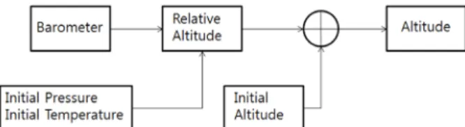
As for the navigation algorithm of a barometer, initially measured pressure is defined as a relative altitude of '0'm, and altitude difference from the initial altitude is provided by converting the pressure measured during driving into a relative altitude. The method for calculating the relative altitude can be expressed as Eq. (8).
0
0
(1 (
s) )
gradient s
gradientGc
T g
T P
h T P
∆ = − (8)
It is an equation for calculating a relative altitude by correcting the pressure depending on temperature. T
0is the
temperature at the initial altitude (absolute temperature), and T
gradientis the temperature change depending on the altitude and has a constant value of 0.0065 [K/m]. Also, P
Sis the pressure measured during the driving of a vehicle, P
s0is the initial pressure, and G
Cis the gas constant (287.052 [J/K*kg]). Fig. 1 shows the entire process of calculating an altitude using a barometer (Lee 2013).
Based on the pressure and temperature measured at the initial position, the relative altitude for the pressure measured during driving was calculated. The final altitude was calculated by adding the initial altitude and the relative altitude. For the initial altitude, an average value of the altitude output of GNSS for one minute at a standstill was used; and the results are shown in Fig. 2.
A barometer is more sensitive to a change compared to GNSS altitude information, and thus, it can better represent the altitude change depending on the movement of a vehicle. However, a barometer is significantly affected by weather and temperature, and thus, the result varies depending on the environment.
The major error of a barometer includes conversion factor error. The altitude information of a vehicle from the barometer considering the error, P
zv, can be expressed by the altitude obtained from the barometer, P
zb, and the conversion factor error, K
zb, as shown in Eq. (9).
Fig. 1. Navigation information generation using a barometer.
Fig. 2. Altitude calculation using a barometer.
zv zb zb zb
P = P + K P (9)
As the barometer was installed at the interior of the vehicle, abrupt temperature change did not occur, and the initial pressure within the vehicle also did not change abruptly. Thus, the conversion factor error of the barometer could be modeled as a random constant. Based on odometer measurements, barometer measurements, and each error model, an integrated navigation system that added an odometer and a barometer to the GNSS/INS integrated navigation system was organized.
The GNSS/INS/odometer/barometer integrated navigation system consisted of the centralized Kalman filter as shown in Fig. 3, and it was implemented based on the 19th-order Kalman filter by adding the error models of the odometer and the barometer to the GNSS/INS integrated navigation system in Chapter 3. The system model can be expressed as Eq. (10).
15 6
6 15 6 6
0 , ~ (0, )
0 0
INS INS
INS
o o CL CL CL
h h
x x
x F x w w N Q
x x
×
× ×
= +
(10)
where F
INSis the system model of the GNSS/INS integrated navigation system in Chapter 3; x
ois the odometer error state variable that consists of the conversion factor error, K
xo, and the non-alignment errors, δψ, δθ; x
his the state variable that represents the conversion factor error of the barometer, K
zb; and Q
CLrepresents the error covariances of INS, the odometer, and the barometer.
The measurement model of the GNSS/INS/odometer/
barometer uses all the GNSS, odometer, and barometer information, and thus it can be expressed as Eq. (11).
, ~ (0, )
INS GNSS
INS
INS GNSS
CL o CL CL CL
n
INS x
n h
INS h
P P
V V x
z H x v v N R
V V
P P x
= − = +
(11)
The measurement model, H
CL, in Eq. (19) is expressed as Eq. (12).
3 3 3 3 3 3 3 6 3 3
3 3 3 3 3 3 3 6 3 3
3 3 3 3 3 3 3 6
11 12 13
21 22 23
31 32 33
1 3 1 3 1 6 1 3
0 0 0 0
0 0 0 0 0
0 0 0 0 0
0 0 0 0
0 0 1 1
CL
x x x
x x x
x x x
I H I
I M
c v c v c v
M c v c v c v
c v c v c v
× × × × ×
× × × × ×
× × × ×
× × × ×
=
− −
= − −
− −
3 3 3 3 3 3 3 6 3 3
3 3 3 3 3 3 3 6 3 3
3 3 3 3 3 3 3 6
11 12 13
21 22 23
31 32 33
1 3 1 3 1 6 1 3
0 0 0 0
0 0 0 0 0
0 0 0 0 0
0 0 0 0
0 0 1 1
CL
x x x
x x x
x x x
I H I
I M
c v c v c v
M c v c v c v
c v c v c v
× × × × ×
× × × × ×
× × × ×
× × × ×
=
− −
= − −
− −
(12)
where c
ijis the component of the coordinate transformation matrix, C
nb.
The GNSS/INS/odometer/barometer integrated navigation system can obtain a navigation solution that corrected the velocity error and altitude error of INS using an odometer and a barometer even in environments without GNSS information.
3. EXPERIMENT AND VERIFICATION
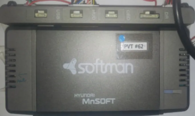
For the experiment environment, the Softman navigation device (Hyundai Mnsoft, http://www.hyundai-mnsoft.com) shown in Fig. 4 was used, and a barometer was separately installed at the vehicle. In the interior of the navigation device, MEMS triaxial accelerometer (AIS328DQ) and triaxial gyroscope (A3G4250D) from ST Company were installed. Also, the TESEOII GNSS receiver (ST Company) Fig. 3. GNSS/INS/odometer/barometer integrated navigation system.
Fig. 4. Navigation system for vehicles (Softman S570).
was installed, and odometer information could be obtained through connection with the vehicle using an On-Board Diagnosis (DBD) cable. For the additionally installed barometer, MEMS barometer sensor (LPS331AP) from ST Company was used (Hyundai MnSoft, http://www.hyundai- mnsoft.com).
Table 1 summarizes the specifications of the MEMS inertial sensors installed at Softman. Also, Table 2 summarizes the specifications of the odometer and the GNSS receiver, and Table 3 summarizes the specification of the barometer.
Using the above navigation device and barometer data, the entire experiment environment was organized as shown in Fig. 5. The sensor output of the navigation device was transmitted to a laptop in an Android environment. For the additionally installed barometer, STM32F103, which is micro controller unit, was additionally installed at the exterior, and the altitude was calculated by obtaining measurements using serial peripheral interface. The calculated altitude information was then transmitted to the laptop via serial communication. Based on this information, the final navigation solution was calculated by the laptop through the suggested integrated navigation algorithm.
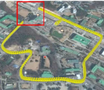
The driving experiment was performed in a driving path on campus shown in Fig. 6. The environment includes uphill roads, downhill roads, and speed bumps, and an area where GNSS signals are not available was made by disconnecting the GNSS antenna on a curved path. In the area where GNSS signals are not available, the error covariance matrix of the Kalman filter, P, was adjusted using the DOP value of the receiver so that improper estimation of the error correction for the sensor due to an abrupt change in the position value could be prevented.
Fig. 7 shows the results of the GNSS/INS and the GNSS/
INS/odometer/barometer based on the driving path on campus when there was no area where GNSS signals are not available. The red inverted triangle represents the GNSS output, the green dot represents the GNSS/INS/Odometer/
Barometer output, and the black star represents the GNSS/
INS output.
To examine the difference between the results of the Fig. 6. Driving path in Chungbuk National University.
Fig. 7. Results of the GNSS/INS and the GNSS/INS/odometer/barometer.
Fig. 5. Experiment environment configuration.
Table 1. Specifications of the inertial sensors.
AIS328DQ A3G4250D
Measurement Range Sensitivity Noise density
±2.0 g 1.81~2.12 mg/digit
100~600 μg/
±250 dps 7.4~10.1 mdps/digit
0.03~0.15 dps/
Output rate 50 Hz
Table 2. Specifications of the odometer and the GNSS receiver.
Odometer TESEOII GNSS receiver
Scale factor 900/637 Multi constellation GPS GLONASS WAAS
Output rate 1 Hz
Table 3. Specification of the barometer.
LPS331AP
Measurement range (mbar)
Pressure RMS noise (mbar) Output rate (Hz)
260~1260 0.02~0.450
1
GNSS/INS and the GNSS/INS/odometer/barometer, the parts marked as circles 1 and 2 in Fig. 7 were magnified as shown in Fig. 8. It was found that the navigation solution calculated using the GNSS/INS/odometer/barometer was more accurate than that using the GNSS/INS.
To compare the two navigation solutions in an area where GNSS signals are not available, an area where GNSS signals are not available was made by arbitrarily disconnecting the GNSS antenna in a curved section within the same driving path, and the performance of the integrated navigation algorithm was examined.
As shown in the red rectangle in Fig. 9, an area where GNSS signals are not available was made for 20 seconds on the driving path in Chungbuk National University. Fig.
10 shows the results of the GNSS/INS and the GNSS/INS/
odometer/barometer integrated navigation system in the area where GNSS signals are not available. To examine the difference between the results of the GNSS/INS and the GNSS/INS/odometer/barometer, the part marked as a circle in Fig. 10 was magnified as shown in Fig. 11.
Fig. 8. Results of the GNSS/INS and the GNSS/INS/odometer/barometer (Magnified).
Fig. 9. Area where GNSS signals are not available in the driving path.
Fig. 10. Navigation system experiment results in the section where GNSS signals are not available.
Fig. 11. Navigation system experiment results in the section where GNSS
signals are not available (Magnified).
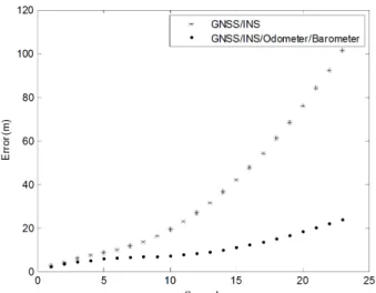
The difference between the position where the position of the navigation system was corrected by the re-reception of GNSS signals and the final position of the section where GNSS signals are not available corresponds to the cumulative position error that occurred during the omission of GNSS signals. Fig. 12 shows the altitude changes of each navigation system, and Fig. 13 shows the magnification of the GNSS outage section. The altitude solution of the GNSS/
INS had a large error since the error accumulated with time, but the GNSS/INS/Odometer/Barometer could calculate an altitude solution that has a smaller error than that of the GNSS/INS through altitude correction. Fig. 14 shows the changes in the two-dimensional navigation solution errors of the GNSS/INS and the GNSS/INS/Odometer/Barometer depending on time in the area where GNSS signals are not available.
Based on the above results, the distance between the final position solution in the area where GNSS signals are
not available for 23 seconds and the first position solution when GNSS signals were received was calculated for the two navigation systems as summarized in Table 4.
It was found that the GNSS/INS/odometer/barometer integrated navigation system could reduce the cumulative horizontal and altitude errors compared to the GNSS/INS integrated navigation system. This is thought to be because the odometer based on an encoder had a smaller error than the low-priced inertial sensor and thus the performance of the two-dimensional solution of the entire navigation system was improved, and because the divergence of the altitude information calculated based on the inertial sensor could be corrected using the barometer.
4. CONCLUSION
In this study, a GNSS/INS/odometer/barometer integrated navigation system that is equipped with low- priced MEMS inertial sensor and GNSS receiver embedded in a commercial navigation device, the odometer of a vehicle, and a low-priced MEMS barometer was implemented, and the performance was verified.
INS using low-priced MEMS sensors can be used for a very short time, and thus, a GNSS/INS integrated navigation system using this would show performance deterioration in areas where GNSS signals are not available. Therefore, a GNSS/INS/odometer/barometer integrated navigation Fig. 13. Altitude solutions of the two navigation systems (Magnified).
Fig. 12. Altitude solutions of the two navigation systems. Fig. 14. Two-dimensional horizontal errors of the two navigation systems.
Table 4. Cumulative errors in the area where GNSS signals are not available.
GNSS/INS GNSS/INS/
Odometer/Barometer