Heat Dissipation of Sealed LED Light Fixtures Using Pulsating Heat Pipe Technology
Hyung-Tak Kim1․Hae-Kyun Park1․Kwang-Hyun Bang†
(Received November 21, 2011; Revised December 20, 2011; Accepted January 6, 2012)
Abstract: An efficient cooling system is an essential part of the electronic packaging such as a high-luminance LED lighting. A special technology, Pulsating Heat Pipe (PHP), can be applied to improve cooling of a sealed, explosion-proof LED light fixture. In this paper, the characteristics of the pulsating heat pipes in the imposed thermal boundary conditions of LED lightings were experimentally investigated and a PHP device that works free of alignment angle was investigated for cooling of explosion-proof LED lights. Five working fluids of ethanol, FC-72, R-123, water, and acetone were chosen for comparison. The experimental pulsating heat pipe was made of copper tubes of internal diameter of 2.1 mm, 26 turns. A variable heat source of electric heater and an array of cooling fins were attached to the pulsating heat pipe.
For the alignment of the heating part at bottom, an optimum charging ratio (liquid fluid volume to total volume) was about 50% for most of the fluids and water showed the highest heat transfer performance. For the alignment of the heating part on top, however, only R-123 worked in an un-looped construction. This unique advantage of R-123 is attributed to its high vapor pressure gradient. Applying these findings, a cooling device for an explosion-proof type of LED light rated 30 W was constructed and tested successfully.
Key w ords: LED, Lighting, Cooling, Pulsating Heat Pipe
†Corresponding Author(Department of Mechanical and Energy Systems Engineering, Korea Maritime University, E-mail: [email protected], Tel:051-410-4365)
1 Department of Mechanical and Energy Systems Engineering, Korea Maritime University
This paper is extended and updated from the short version that apeared in the Proceedings of the International symposium on Marine Engineering and Technology (ISMT 2011), held at BEXCO, Busan, Korea on October 25-28, 2011.
1. Introduction
Recent environmental concern of carbon dioxide- induced global warming as well as high oil price has recalled again the increasing demand of high efficiency energy systems. In lighting industry, the high-efficiency LED (Light Emitting Diode) is expected to replace the conventional lighting systems [1].
However, the LEDs, the light sources, are semiconductors which require much lower operating temperature compared to the conventional electric light bulbs. Insufficient dissipation of the heat
produced in the LEDs (typically ~90% of the power consumed) could cause a reduction of the LED lifetime as well as the luminance. Heat dissipation of the LED lighting is, therefore, one of the key technologies that can provide the reliability of the LED lighting systems [2].
In this study, a Pulsating Heat Pipe (PHP) has been considered as a potential candidate for the improvement of cooling performance in the LED lighting systems. A pulsating heat pipe is an efficient heat transport device that employs two-phase flow of evaporation and condensation inside small-diameter
tube. It is simple in construction, low cost, and as long as a temperature difference exists, heat is rapidly transferred without an external power. Such advantages of the PHP have attracted various electronic packaging industries that have demanded an efficient cooling technology [3].
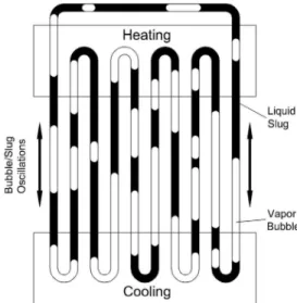
A typical pulsating heat pipe consists of many capillary tubes that are connected in series or a long tube is bent at every equal length (Figure 1). The tube is first vacuumed and then a working fluid is charged by part of the total internal volume. The liquid fluid flowing through heated part evaporates and the vapor fluid flowing through cooled part condenses. The higher pressure in the evaporating part and the lower pressure in the condensing part induce an oscillating flow and this is the principle of the pulsating heat pipe that transfers heat efficiently from higher temperature to lower temperature [4].
The pulsating heat pipes are classified in three types by their construction: closed-loop, open-loop, and closed-loop with check valve. In closed-loop type, the two ends of the tube are connected and they are not connected in open-loop type. A closed-loop type generally shows better heat transfer performance than the open-loop type [4]. Also it was reported that the closed-loop type with check valve showed better thermal performance than the closed-loop without check valve due possibly to the role of the check valve [5]. A closed-loop type without check valve is the simplest in construction and thus it is the most common type in the past work. In the present study, a closed-loop type pulsating heat pipe was mainly investigated.
In the past, many experimental and analytical works have been performed to investigate the pulsating flow characteristics and design parameters that influence the heat transfer performance of the pulsating heat pipes. Kim et al. [4] performed an experiment using a PHP consisting of twenty rectangular channels of 1.5 by 1.5 mm. They
observed highly oscillating two-phase flow in slug and slug-annular flow pattern. Also in case of increased number of channels and heat flux, the oscillation frequency increased and when steady-state was reached the circulation direction was fixed and unchanged. Tong et al. [6] also observed similar behavior in their experiment using fourteen channels of 1.8 mm inner-diameter round tube.
Figure 1: Schematic of a loop type PHP
Xu and Zhang [7] measured the tube wall temperatures in their experiment consisting six channels of 2 mm inner-diameter tubes. The measured wall temperatures showed a periodic pattern that implied that the flow pattern was slug flow with evenly distributed liquid and vapor slugs.
The physical parameters that influence the operation and performance of the pulsating heat pipes are known to be tube diameter, thermal conditions (i.e., temperature range), type of working fluid, charging ratio, number of channels, and the arrangement (or inclination against gravity direction).
Clear understanding and quantitative evaluation of the effect of these parameters on the PHP performance are crucial to the optimum design of the PHP for various application fields [8-10].
Unfortunately, however, a difference exists in the effect of these physical parameters learned from the past studies and it is difficult to directly compare the results because even with same fluid a slight difference in experimental apparatus changed the results. For example, an optimum charging ratio is known to be 20-80%, so wide range or rather vague.
Besides, there has been no consensus on which is more influencing among sensible heat and latent heat and also on the preferred magnitude of surface tension.
The alignment angle of the tube against the direction of gravity is also important for the PHP performance; i.e. vertical with the heating part at bottom, vertical with the heating part at top, or horizontal layout. It has been reported that smaller tube diameter or increased number of tubes can diminish the effect of gravity [11]. However, an optimum size of tube diameter or an optimum number of tubes is not known due to the fact that the experimental result seems to be highly sensible to individual experimental setup.
Despite of extensive experimental and analytical study on the pulsating heat pipes in the past decade, a complete design methodology or an optimum design procedure is not well established yet and an industrial application of the PHPs is very scarce. In the present study, the characteristics of the pulsating heat pipes in the imposed thermal boundary conditions of LED lightings were experimentally investigated and a PHP device that works free of alignment angle was investigated for cooling of explosion-proof LED lights.
2. Experiment
2.1 Working Fluid
Five working fluids of ethanol, FC-72, R-123, water,andacetoneweretestedinan8-turn,loopedpulsatinghe atpipewhereheatingwasatbottomandcoolingwasontop[12].
It was constructed using copper tubes of 3.18 mm of
outer diameter and 2.1 mm of inner diameter. Hot and cold water loops were used for heating and cooling of the PHP. For the fixed heating temperature of 70℃, cooling temperature of 25℃, water flow rate of 1 LPM, the charging ratio was varied from 20%
to 70% for each working fluid.
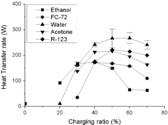
For each of working fluid and charging ratio, the heat transfer rates are given in Fig. 2. The optimum charging ratio is observed for each fluid: 50-60% for water and R-123, 40-50% for FC-72 and acetone, 30-40% for ethanol. The best heat transfer performance was obtained with water, as high as 250 W, then R-123, acetone, FC-72, ethanol in decreasing order.
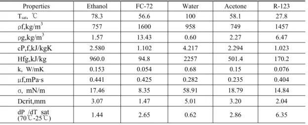
The highest heat transfer performance of water can be attributed to its high specific heat and latent heat of vaporization, which are twice larger than those of other fluids, as shown in the comparison of physical properties of Table 2.
For the alignment of heating on top, none of these fluids made the pulsating heat pipe working. This is probably because the way the vapor produced in the heating part moves is aligned in opposite of the buoyancy force. A past study reported that smaller tube diameter or increased number of tubes can diminish the effect of gravity [11].
Figure 2: Effect of working fluid and charging ratio on heat transfer rate in looped PHP with heating at the bottom
Table 1: Physical properties of saturated fluids at 1 atm.
Properties Ethanol FC-72 Water Acetone R-123
Tsat, ℃ 78.3 56.6 100 58.1 27.8
ρf,kg/m3 757 1600 958 749 1457
ρg,kg/m3 1.57 13.43 0.60 2.27 6.47
cP,f,kJ/kgK 2.580 1.102 4.217 2.294 1.023
Hfg,kJ/kg 960.0 94.8 2257 501.4 170.2
k, W/mK 0.153 0.054 0.68 0.15 0.076
μf,mPa·s 0.441 0.425 0.282 0.235 0.404
σ, mN/m 17.46 8.35 58.91 18.79 14.84
Dcrit,mm 3.07 1.47 5.01 3.20 2.04
dP /dT sat
(70℃-25℃) 1.44 2.65 0.62 2.86 6.35
In the present study, a PHP with an increased number of turns was tested with the five working fluids for both alignments in order to find a PHP that works free of alignment angle.
2.2 Experimental Apparatus
An experimental pulsating heat pipe was constructed using copper tubes of 3.18 mm of outer diameter and 2.1 mm of inner diameter. The number of tube turns was 26 each in the heating and cooling parts. The tube lengths were 134 mm for the heating and the cooling part each and 134 mm for the adiabatic part. To connect the heat pipe to a heating device and also to a cooling device, one side of an aluminum plate of 134 x 134 mm in size was grooved as shown in Fig. 3. The width of the groove was 3 mm to make a good contact with the PHP tubes that were inserted into the grooves. Two grooved plates were made and one is for the heater to the heat pipe and the other for the cooling fins to the heat pipe.
The heating part was made of four film heaters, each size was 50 x 50 mm. The maximum heat flux allowed was 15.5 kW/m2 and the maximum temperature allowed is 120oC. The AC electric power to these heaters was controlled using a voltage transformer and measured using an AC power
meter to get the power input to the heat pipe. The cooling was made in ambient air using an array of aluminum cooling fins. A schematic diagram of the experimental apparatus is shown in Fig. 4. This figure shows the bottom-heat alignment and the top-heat alignment can be easily made by turning the upside down.
The experimental parameters are summarized in Table 2. Throughout the experiment, the heating temperature was kept at 70oC and the ambient temperature was 25oC to provide a typical thermal condition of LED lights. The heat dissipation rate was obtained by measuring the electrical power to the heaters.
In this experiment, three working fluids were tested: FC-72, water, and R-123. Ethanol and acetone were not used because of their flammable nature in an explosion-proof application. Some selected physical properties of the working fluids are summarized in Table 1. The charging ratio, defined as the ratio of liquid working fluid charged to the total volume, was set at 50%, which was experimentally found to be an optimum value [12]. Every time the fluid was charged, the system was first completely vacuumed down to 5 kPa and any noncondensable gas (air) was prevented to enter the system using a specially designed charging system using a three-way valve.
Figure 3: Grooved Aluminum Plate for PHP Contact.
Figure 4: Experimental apparatus (Bottom Heated).
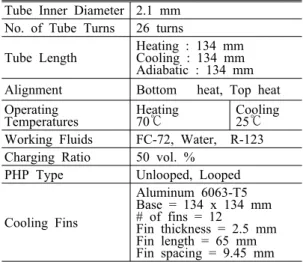
Table 2: Experimental parameters.
Tube Inner Diameter 2.1 mm No. of Tube Turns 26 turns
Tube Length Heating : 134 mm Cooling : 134 mm Adiabatic : 134 mm Alignment Bottom heat, Top heat Operating
Temperatures Heating
70℃ Cooling
25℃
Working Fluids FC-72, Water, R-123 Charging Ratio 50 vol. %
PHP Type Unlooped, Looped
Cooling Fins
Aluminum 6063-T5 Base = 134 x 134 mm
# of fins = 12
Fin thickness = 2.5 mm Fin length = 65 mm Fin spacing = 9.45 mm
The temperatures were measured using T-type thermocouples at the heater surface, cooling fin base, and some locations on the tube surface in the adiabatic region. The temperature data were monitored and recorded using a Labview data logger.
3. Results and Discussion
3.1 Effect of Alignment and Working Fluid
The objective of this study is to find a cooling device applicable to a flameproof LED light which is free of alignment angle; i.e., the cooling must work properly in both bottom heated and top heated pulsating heat pipes. The tests were conducted with three working fluids of FC-72, water, and R-123. The heated part was kept at 70oC and the ambient air at 25oC The fluid charging was 50% in volume known as an optimum value. Both the looped type and unlooped type were tested.
When the heating was at the bottom, all cases were working and the water showed the largest amount of heat dissipation. Looped type performance was better than the unlooped type.
When the heating was on the top, however, none of the cases except the R-123 fluid in unlooped type worked. This was an interesting finding for an application of pulsating heat pipes to a free-of- alignment cooling device. The unique advantage of R-123 that makes the pulsating heat pipes in top-heated mode can be attributed to its high value of vapor pressure gradient; i.e., the value of dPsat/dT. As seen in Table 1, the average value over 25-70oC is 6.35 for R-123, but 0.62 for water.
The temperature traces obtained in the test with R-123 is shown in Fig. 5. It is shown that in the top-heat mode with unlooped type, the heat transfer was stable, but with looped type, the pulsating heat pipe did not work properly. The heat transfer rate in each case of R-123 tests is compared in Table 3. In unlooped type, the heat transfer rate in top heated mode is smaller than that of bottom heated mode by 30%.
Figure 5: Temperature traces in test with R-123
Table 3: Comparison of heat transfer rate with R-123
Alignment Looped Unlooped
Bottom Heating 62 W 56 W
Top Heating Not working 39 W
3.2 Application to 30 W LED Light
The experimental findings in the present study provide the design basis of the cooling device for a flameproof LED light which can work free of alignment angle. The top-heated, flameproof LED light can be cooled using an unlooped type, pulsating heat pipe, charged with 50% liquid R-123 in volume.
In order to demonstrate this cooling technology, a 30 W-rated LED light was equipped with a pulsating heat pipe, as shown in Fig. 6. To accommodate the size of the LED light base, the number of tube turns was reduced to 18 and the sane 2.1 mm ID copper tube was used for the pulsating heat pipe construction. Also a thermal analysis of the cooling device showed that the size of the cooling fins can be reduced to 8 fins to keep the temperature of the heating part at about 70oC. The tube lengths were 63 mm for the heating and the cooling part each and 105 mm for the adiabatic part. The body of the pulsating heat pipe was wrapped with four acrylic plates and sealed from the ambient air to simulate a flameproof construction.
Figure 6: Construction of 30 W LED light cooling (Top Heated).
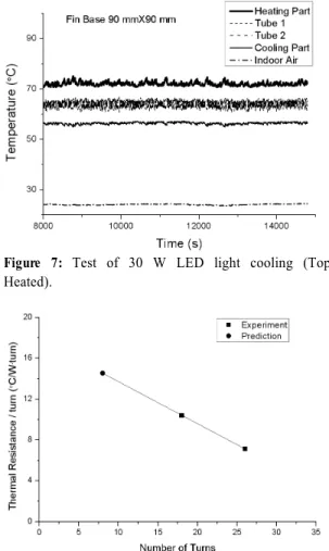
Figure 7: Test of 30 W LED light cooling (Top Heated).
Figure 8: Effect of tube turns on thermal resistance of pulsating heat pipes.
The test results of the cooling device for 30 W LED light is shown in Fig. 7. It is seen that the temperature of the LED PCB was maintained at about 70oC and the cooling fin base temperature was as high as 55oC.
3.3 Thermal Resistance
Despite that the thermal resistance of pulsating heat pipes is one of the key elements in designing the heat pipes, it is difficult to quantitatively estimate since it involves evaporation and condensation inside a capillary-size tube. In the present study, two different number of tube turns, 18 and 26, were tested, thus it is worth to evaluate the thermal resistance of pulsating heat pipes based on the experimental data.
Since it can be assumed that each tube turn connects the heating part and the cooling part in parallel, the thermal resistance of one tube turn is the product of the total resistance and the number of turns. Using the experimental data, it is 10.4 oC/W for 18-turn PHP and 7.15oC/W for 26-turn PHP.
These
two values are plotted in Fig. 8. If it is assumed that the thermal resistance per turn is linearly related to the number of turns, it is 14.6oC/W for the 8-turn PHP, which was used in obtaining the results shown in Fig. 1. Using this value for 8-turn heat pipe, the heat transfer rate is 24 W, which is much lower than the heat transfer rates shown in Fig. 1. This can explain why the R-123 case did not work in top heated mode of 8-turn system.
4. Conclusion
Despite of extensive experimental and analytical study on the pulsating heat pipes in the past decade, a complete design methodology or an optimum design procedure is not well established yet and an industrial application of the PHPs is very scarce. In the present study, the characteristics of the pulsating heat pipes in
the imposed thermal boundary conditions of LED lightings were experimentally investigated and a PHP device that works free of alignment angle was investigated for cooling of explosion-proof LED lights. Five working fluids of ethanol, FC-72, R-123, water, and acetone were chosen for comparison.
The experimental pulsating heat pipe was made of copper tubes of internal diameter of 2.1 mm, 26 turns. A variable heat source of electric heater and an array of cooling fins were attached to the pulsating heat pipe. For the alignment of the heating part at bottom, an optimum charging ratio (liquid fluid volume to total volume) was about 50% for most of the fluids and water showed the highest heat transfer performance. For the alignment of the heating part on top, however, only R-123 worked in an un-looped construction. This unique advantage of R-123 is attributed to its high vapor pressure gradient.
Applying these findings, a cooling device for an explosion-proof type of LED light rated 30 W was constructed and tested successfully.
Acknowledgement
This research was supported by the MKE (the Ministry of Knowledge Economy), Korea, under the ITRC (Information Technology Research Center) support program supervised by the NIPA (National IT Industry Promotion Agency) (NIPA-2011-C1090-1121- 0015).
References
[1] M.S. Yoon, “Present and future of lighting industry”, Bulletin of KIEEME, vol. 21, pp.
21-26, 2008(in Korean).
[2] M.H. Shin, “State of the art on a large output of power LED packaging.” Physics & High Technology, The Korea Physical Society, pp.
16-21, 2008.
[3] Groll M., and Khandekar S., Pulsating Heat Pipes: Progress and Prospects, Proceeding of the
International Conference on Energy and the Environment, Shanghai, China, vol. 1, pp. 723–
730, 2003.
[4] J.S. Kim, N.H. Bui, J.W. Kim, J.H. Kim and H.S. Jung, “Flow visualization of oscillation characteristics of liquid and vapor flow in the oscillation capillary tube heat pipe.”, Journal of the Korean Society of Mechanical Engineers International Journal, vol. 17, no. 10, pp.
1507~1519, 2003.
[5] S. Rittidech, N. Pipatpaiboon and P. Terdtoon,
“Heat-transfer characteristics of a closed-loop oscillating heat-pipe with check valves”, Applied Energy, 84, pp. 565-577, 2006.
[6] B. Y. Tong, T. N. Wong and K. T. Ooi,
“Closed-loop pulsating heat pipe”, Applied Thermal Engineering, 21, pp. 1845-1862, 2001.
[7] J. L. XU and X. M. Zhang, “Start-up and steady thermal oscillation of a pulsating heat pipe.”
Heat Mass Transfer, vol. 41, pp. 685-694, 2005.
[8] P. Charoensawan, S. Khandekar, M. Groll and P.
Terdtoon, 2003, “Closed loop pulsating heat pipes – Part A: Parametric experimental investigations”, Applied Thermal Engineering, 23, pp. 2009-2020, 2003.
[9] S. Khandekar, N. Dollinger, M. Groll,
“Understanding operational regimes of pulsating heat pipes: an experimental study”, Applied Thermal Engineering, 23, pp. 707-719, 2003.
[10] Honghai Yang, S. Khandekar and M. Groll,
“Operational limit of closed loop pulsating heat pipes”, Applied Thermal Engineering, 28, pp.
49-59, 2008.
[11] Zhang, Yuwen and Faghri, Amir, “Advances and Unsolved Issues in Pulsating Heat Pipes”, Heat Transfer Engineering, vol. 29, no. 1, pp. 20-44, 2008.
[12] H. T. Kim, “A Study on Cooling of Flameproof LED Lightings using Pulsating Heat Pipes,” M.S.
Thesis, Korea Maritime University, 2012.
저 자 소 개
Hyung-Tak Kim
He received his B.S. degree in Refrigeration and Air-conditioning Engineering from Korea Maritime University in 2010. He is an M.S. student in Refrigeration and Air-conditioning Engineering at Korea Maritime University.
Hae-Kyun Park
He received his B.S. degree in Refrigeration and Air-conditioning Engineering from Korea Maritime University in 2011. He is an M.S.
student in Refrigeration and Air-conditioning Engineering at Korea Maritime University.
Kwang-Hyun Bang
He received his B.S. degree in Nuclear Engineering from Seoul National University in 1981, M.S. in Nuclear Engineering from Purdue University in 1985, and Ph.D. in Nuclear Engineering from University of Wisconsin-Madison in 1989, He has been a professor of Mechanical and Energy Systems Engineering at Korea Maritime University since 1996.