1. Introduction
Nowadays steels used for the nuclear power system, steam and gas turbines, aircraft, marine structures, pipe- lines, and automotives are recommended to be high strengthening [1–3]. To enhance the mechanical property, various researches have been tried. Among them, grain refinement is one of the effective ways to improve me- chanical property because both strength and toughness can be improved at the same time according to the Hall-Petch equation (d-1/2 law). There are techniques of controlling grain size such as deoxidation practice during steel pro- ducing and controlled rolling [4]. The final grain size of heat-treated medium carbon steel is mainly controlled by the prior austenite grain size. It is determined by competi- tion between the driving forces for recrystallization and grain growth, and grain boundary pinning. The grain boun- dary pinning is occurred by solute atoms and precipitate.
Especially, addition of microalloy elements has an effect on the grain boundary pinning. There are some researches concerning microalloy additions of transition metal ele- ments such as V, Ti, Nb which play a critical role in refining the grain size. Among them, niobium is known as one of the most effective elements to grain refinement [5]. The atoms are clustered within the austenitic solid
solution or are nucleated as discrete second phase carbides, nitrides and carbo-nitride precipitates [6,7]. Earlier research reported that the second phase precipitates were more effec- tive to pin grain boundaries than the solute atoms [8,9].
However, these high strength steels in the industries are likely to affect corrosion fatigue due to the deleterious envi- ronments and operating conditions [3,10-12]. Furthermore, these precipitates increase the susceptibility of high strength steel to localized corrosion, and the locally cor- roded site acts as a stress raiser such as a notch, hole, and pitting. Therefore, the resistance of high strength steel to environmental induced crack is deteriorated. Especially the higher strength material is more sensitive to adverse effect of notch. Since the higher strength steel is more susceptible to the stress raiser, the inclusion is more im- portant factor [13]. Furthermore, high strength steels with yield strength greater than 1000 MPa or HV ~ 350 are dramatically susceptible to hydrogen embrittlement in a hydrogen environment [14]. The higher strength level of steel has the lower amount of allowable diffusible hydro- gen content. Additionally, the hydrogen distribution is as significant as the average diffusible hydrogen content at this lower hydrogen level. The precipitates are known as not only effective factor of hydrogen diffusion, but also initiation site of hydrogen-induced fracture in high strength steel [15-17]. For these reasons, it is important to study the influence of inclusions on the environmentally assisted
Effect of Niobium on Corrosion Fatigue Properties of High Strength Steel
Young-Joo Cho, Sang-Won Cho, and Jung-Gu Kim†
School of Materials Science and Engineering, Sungkyunkwan University, 2066 Seobu-ro, Jangan-gu, Suwon-si, Korea (Received January 29, 2018; Revised April 03, 2018; Accepted April 17, 2018)
In this study, the effect of Nb alloying element on the corrosion fatigue properties of high strength steel is investigated by conducting fatigue experiments under corrosive condition and hydrogen induced condition, potentiodynamic polarization test, tensile test and surface analyses. Nb element is added to enhance the mechanical property of medium carbon steel. This element forms MX-type phases such as carbides and nitrides which are playing an important role in the grain refinement. The grain refinement is one of the effective way to improve mechanical property because both tensile strength and toughness can be improved at the same time. However, MX-type phase precipitates can be a susceptible site to localized corrosion in corrosive environment due to the potential difference between matrix and precipitate. The obtained results showed that Nb-added steel improved corrosion fatigue property by grain refinement. However, it is degraded for hydrogen-induced fatigue property due to Nb, Ti-inclusions acting as a stronger trap.
Keywords: High strength steel, Corrosion fatigue, SEM, Localized corrosion, Inclusion
†Corresponding author: [email protected]
fatigue behaviour of high strength steel.
In this study, corrosion fatigue properties of high strength steel with the addition of Nb alloying element were eval- uated in 5% NaCl solution. The mechanical properties of high strength steel are evaluated by tensile test. For the analysis of fatigue life in corrosive and hydrogen induced environments, fatigue tests were conducted at open-circuit potential (OCP) and -1.8 VSCE in 5% NaCl. Furthermore, microstructures and inclusions are observed by optical mi- croscopy and scanning electron microscopy (SEM).
2. Experimental Methods
2.1 Specimen and solution preparation
Two high strength steels were used to study the effect of Nb on the corrosion fatigue behaviour. The specimens consisted of V-Ti steel (S1) and V-Ti-Nb steel (S2).
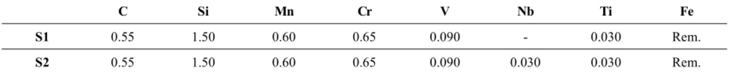
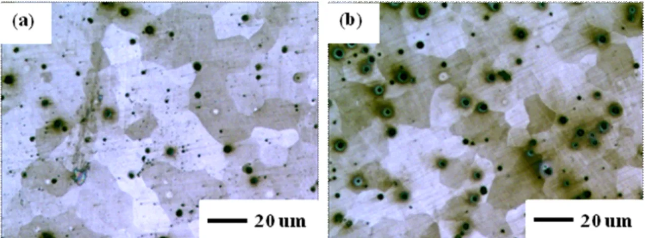
Detailed compositions of two steels were listed in Table 1. The surface of each specimen was abraded with silicon carbide (SiC) papers down to 1000 grit. The specimens were rinsed with ethanol and finally dried with air. The etching solution is the 2% nital solution. In the ni- tal-etched specimens, tempered martensite microstructure was observed on each specimen as shown in Fig. 1.
2.2 Potentiodynamic polarization tests
Potentiodynamic polarization test was carried out to compare S1 with S2 using a conventional three-electrode cell. A potential was stabilized for 2 h before the electro- chemical test. After that, the potentiodynamic polarization
tests were conducted in accordance with ASTM G5 with a potential sweep of 0.166 mV/s from -50 mV vs open-cir- cuit potential (OCP) to a final potential of 0 VSCE for the anodic polarization, and from an initial potential of +50 mV vs open-circuit potential (OCP) to a final poten- tial of -2.0 VSCE for the cathodic polariztion.
2.3 Tensile and corrosion fatigue tests
Cylindrical tensile specimens were made from the high strength steel rods according to the ASTM E8 as shown in Fig. 2. The gauge section of specimen is 16 mm in length and 4 mm in diameter. Tensile tests were conducted at a strain rate of 3 x 10⁻⁵ s-1. The results were analysed for the yield strength (YS), tensile strength (TS) and duc- tility (% total elongation).
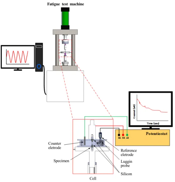
Corrosion fatigue tests were carried out using a corro- sion fatigue testing apparatus as shown in Fig. 3, with a sinusoidal cyclic frequency of 0.5 Hz and a stress ratio of ~ 0.43 in 5% NaCl solution. The stress range was 6000 N to 14000 N which correspond with 30 – 70% of yield Table 1 Chemical compositions (wt%) of the tested specimens
C Si Mn Cr V Nb Ti Fe
S1 0.55 1.50 0.60 0.65 0.090 - 0.030 Rem.
S2 0.55 1.50 0.60 0.65 0.090 0.030 0.030 Rem.
Fig. 1 Microstructures of (a) S1 and (b) S2 using 2% Nital etching solution.
Fig. 2 Schematic diagram of the cylindrical specimen (dimensions in mm).
stress (YS) at open-circuit potential and at potentiostatically controlled cathodic potential. The test cell consisted of a PVC vessel, two graphite counter electrodes and a Luggin probe were introduced into the cell. A saturated calomel electrode (SCE) was used as the reference electrode. Except the gauge length area, the rest part of specimen was masked with silicon. The specimens were abraded with silicon car- bide (SiC) papers down to 1000 grit.
2.4 Surface analysis
To investigate prior austenite grain, the specimens were abraded with silicon carbide (SiC) papers down to 2000 grit and then polished with 1 µm diamond suspension.
The specimens were rinsed with ethanol and finally dried with air and then etched with a picric acid solution for observing prior austenite grain. The microstructure was examined by scanning electron microscopy (SEM).
Precipitates were examined by back scattered electron (BSE) mode of SEM and energy-dispersive spectroscopy (EDS) and image analysis.
To investigate the potential difference between the pre- cipitates and steel matrix, the specimens exposed to 5%
NaCl for 5 minutes were examined by Kelvin probe force microscopy (KPFM). The composition of precipitates was examined by electron probe micro-analyzer (EPMA).
Counter eletrode
Specimen
Cell
Reference eletrode Luggin probe Silicon Fatigue test machine
Fig. 3 Schematic of corrosion fatigue test system.
3. Results and Discussion
3.1. Potentiodynamic polarization tests
Fig. 4 shows the potentiodynamic polarization curves of S1 and S2 in 5% NaCl solution. Both alloys show active corrosion behaviour without passive state. The corrosion current density slightly decreased with the niobium addition. The anodic polarization curves of S1 and S2 specimens have a similar shape, and the corrosion poten- tials of the two specimens were close to -650 mVSCE. However, the cathodic polarization curve of S2 is shifted slightly to higher current density direction than S1. The transition metal elements for micro alloy such as V, Ti, Nb are known as strong carbide and nitride formers which are effective to make fine grain. Actually, transition metal carbide and nitrides act as a catalyst which promotes re- duction reaction. Especially, these transition metal carbide and nitrides were mainly observed as a HER catalyst (Hydrogen Evolution Reaction, 2H++ 2e- à H2) [18,19].
In an aerated condition, there are three possible candidate reduction reactions on the surface in the cathodic polar- ization behaviour.
O2 + 4H+ + 4e- à 2H2O (1)
2H+ + 2e- à H2 (2)
2H2O + 2e- à H2 + 2OH- (3) Based on the behaviour of cathodic polarization curves in Fig. 4, the oxygen reduction reaction is dominant down to -1.1 VSCE, with the oxygen diffusion limit occurring at about 0.11 mA/cm2 for S1 and about 0.16 mA/cm2 for
S2. Above the equilibrium potential for the hydrogen re- actions only oxygen reduction reaction will occur. The equilibrium electrode potential for hydrogen evolution can be calculated by the Nernst equation which is -636 mVSCE
in the solution at 25 oC and pH 6.7. In the case of S1 and S2, the (1) ~ (3) reactions are occurred on the basis of thermodynamics. The hydrogen production is dominant below a potential of -1.1 VSCE with the diffusion limit of about 102 mA/cm2. The main mechanism of fatigue fracture for the high strength steel was known as corrosion failure and/or hydrogen induced failure. To study fatigue failure for the effect of these main mechanisms, corrosion fatigue tests are conducted at open-circuit potential con- dition for corrosive effect and at -1.8 VSCE for accelerated hydrogen induced effect.
3.2. Tensile test behaviour
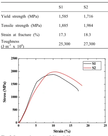
The uniaxial tension stress-strain curves for S1 and S2 are shown in Fig. 5 and a summary of the stress-strain curves is listed in Table 2. The yield strength and tensile strength of S2 specimen are higher than S1 specimen. Not only the strength, but also strain at fracture of S2 specimen is higher than S1 specimen. From stress-strain curves, toughness of two specimens can be evaluated by calculat-
10-8 10-7 10-6 10-5 10-4 10-3 10-2 10-1 100 -2.0
-1.5 -1.0 -0.5 0.0
Potential (VSCE)
Current density (A/cm2) S1
S2
Fig. 4 Potentiodynamic polarization curves of S1 and S2 in 5%
NaCl solution.
Table 2. Mechanical properties of S1 and S2 from stress-strain curves
S1 S2
Yield strength (MPa) 1,585 1,716 Tensile strength (MPa) 1,885 1,984 Strain at fracture (%) 17.3 18.3 Toughness
(J·m-3 x 10⁴) 25,300 27,300
0 5 10 15 20 25
0 500 1000 1500 2000 2500
Stress (MPa)
Strain (%)
S1 S2
Fig. 5 Stress-strain curves of S1 and S2.
ing the underneath area of the curves. From calculated toughness value, S2 specimen has higher toughness value than S1 specimen. These results suggest that the Nb addi- tion acts as a strength and toughness enhancer. It is known that the addition of V, Ti, Nb is effective for grain refinement. The final grain size of heat-treated medium carbon steel is mainly controlled by the prior austenite grain size. It is determined by competition between the driving forces for recrystallization and grain growth, and grain boundary pinning. The grain boundary pinning oc- curs by solute atoms and precipitate. As mentioned pre- viously, elements (V, Ti, Nb) are clustered within the aus- tenitic solid solution or are nucleated as discrete second phase carbides, nitrides and carbon-nitride precipitates [6,7]. Earlier research reported that the second phase pre- cipitates were more effective in pinning grain boundaries than the solute atoms [8,9]. Among them, niobium is known as one of most effective elements for grain refine- ment [5].
To observe prior austenite grain, S1 and S2 are etched by prior austenite etching solution and the microstructures are shown in Fig. 6. The average prior austenite grain size of S2 (~ 18 μm) shows more refined grain size than S1 (~ 30 μm).
3.3. Fatigue test behavior on corrosive condition Prior to the corrosion fatigue tests, air fatigue tests are conducted under the same condition. As a result, the fa- tigue life of the specimens amounted over 107 cycles which are corresponded to fatigue limit.
Fig. 7 shows the fatigue lives of S1 and S2 in 5% NaCl solution at open-circuit potential for the evaluation of cor- rosion effect. The fatigue lives of two steels are 12,790 and 21,594 cycles, respectively. Compared with the fatigue life in air, the fatigue lives of the corrosive environment
are markedly deteriorated at least 500 times. Fatigue crack initiation is generally influenced by small and large metal- lurgical defects. Among the defects, inclusions are known as a critical factor influencing mechanical properties.
Furthermore, especially the larger inclusion is more prefer- ential site for fatigue crack and reduces the fatigue life [20,21]. In corrosive environments, inclusion is a more remarkable factor associated with a localized chemical process due to the different electrochemical potential be- tween matrix and inclusion. Especially, the higher strength steel is more susceptible to the stress raiser such as notch.
Impurities are more important in the corrosive environment in terms of pit-maker by localized corrosion [13]. Fig. 7 also shows the better corrosion fatigue resistance of Nb-containing steel compared to the Nb-free steel.
For these reasons, the inclusions in S1 and S2 are exam- ined by using BSE mode of scanning electron microscopy (SEM) and energy-dispersive spectroscopy (EDS). From the results of observation, Ti(C,N) was observed only on Fig. 6 Microstructures of (a) S1 and (b) S2 using etching solution for revealing the prior austenite.
0 5000 10000 15000 20000 25000 30000
S2 S1 21,594 S2
S1
Number of cycles to Failure(# of cycles)
12,790
Fig. 7 Fatigue life of S1 and S2 in 5% NaCl at open-circuit poten- tial for the evaluation of corrosion effect.
S1 and (Nb,Ti)(C,N) was observed only on S2. Ti(C,N) and (Ti,Nb)(C,N) are known as the impurities decreasing corrosion fatigue life due to that of noble electrochemical potential than metal matrix in the corrosive environment.
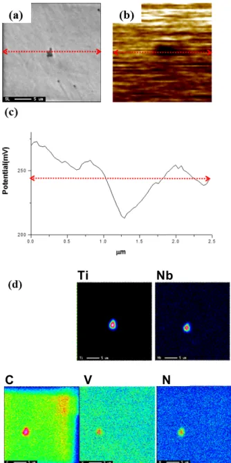
The morphologies and EDS for Ti(C,N) in S1 and (Nb,Ti)(C,N) in S2 are shown in Fig. 8a and Fig. 9a.
The pinning force of carbide and nitride precipitates is the highest when the size of precipitates is l – 20 nm [23-25]. However, the oversized inclusions are detected considerably in this study and the average size is over 10 μm. In addition, the inclusions are elongated along rolling direction and inclusion cluster. Fatigue cracking initiated from the Ti-precipitates by the result of inter- action between mechanical and electrochemical factors has been reported [26,27]. Fig. 8c and Fig. 9c show that the potentials of Ti(C,N) and (Ti,Nb)(C,N) differed from the potential of matrix. Fig. 10 is a schematic diagram of the process of fatigue crack initiation at precipitate on
the basis of these works. The Ti(C,N) are more stable and harder than matrix. The matrix nearby Ti(C,N) acts as an anode and dissolves preferentially in the solution and the corresponding anodic reaction is as follows (Fig. 10b).
Fe à Fen+ + ne- (4)
Ti(C,N) precipitates acts as a cathode and the basic re- actions are as follows:
Fig. 8 (a), (b) Morphology of Ti(C, N) inclusion, (c) the potential profile of the specimen, (d) EDS for each inclusion of S1 specimen.
Ti Nb
C V N
Fig. 9 (a), (b) Morphology of (Nb,Ti)(C, N) inclusion, (c) the potential profile of the specimen, and (d) EDS for each inclusion of S2 specimen.
H+ + e- à Habs (5)
O2 + H2O + 4e- à 4OH- (6)
The (Ti,Nb)(C,N) is also qualified to be a cathodic site which induces micro-galvanic reaction. (Ti,Nb)(C,N) is not only reduction catalyst, but also it has a high mechan-
ical strength, high electron conductivity and higher elec- trochemical potential than Fe [18]. The potentiodynamic test results of Ti(C,N) and (Ti,Nb)(C,N) sputtering coat- ings in saline solution studied by J.C. Caicedo et al. [28]
confirmed those observations. From these report, it can be known that the Ti(C,N) and (Ti,Nb)(C,N) have higher electrochemical potentials than the substrate.
Not only electrochemical reaction, the dislocation is stacking near the precipitate and the dislocations increase by cyclic load (Fig. 10a). The matrix nearby Ti(C,N) stacks a lot of dislocations and suffers from serious plastic strain, which enhances electrochemical activity and accel- erates anodic dissolution (Fig. 10b). Once a pit formed, stress or strain concentration occurs at the tip of pit and an active slip plane appears from it. The microcrack is developed along the slip plane (Fig. 10c). The developing microcrack decelerates approaching the prior austenite grain boundary under cyclic load. The prior austenite grain boundaries act as a barrier of crack propagation [22,29].
Moreover, brittle intergranular fracture occurs along the prior austenite grains [17]. Actually, many mechanical properties can be improved by refining the grain size.
Grain refinement affects not only the case of strength and toughness, but also it affects the fatigue strength. In this study, the prior austenite grain size is important in terms of corrosion fatigue life because the average inclusion size of S1 and S2 is not remarkably different. For these rea- sons, the corrosion fatigue life of S2 had higher than S1 due to the smaller size of prior austenite grain size.
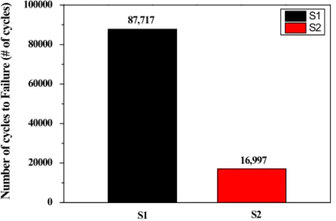
3.4. Fatigue test behavior under hydrogen induced condition Fig. 11 shows fatigue life of S1 and S2 in 5% NaCl solution at the potential of -1.8 VSCE for the evaluation of hydrogen induced effect. Each specimen is failed at 87,717 and 16,997 cycles, respectively. The higher strength Fig. 10 Schematic of corrosion fatigue crack initiated at precipitates.
0 20000 40000 60000 80000 100000
16,997
S2
S1 87,717 S2
S1
Number of cycles to Failure (# of cycles)
Fig. 11 Fatigue life of S1 and S2 in 5% NaCl at - 1.8 VSCE for hydrogen induced effect.
steel is known that the susceptibility of hydrogen induced cracking increases, since the amount of hydrogen which diffuse into the substrate decreases. Moreover, the local hydrogen concentration is important rather than its aver- age total amount in the case of higher strength steel [17].
There are factors to locally concentrate the hydrogen such as the interfaces between matrix and non-metallic in- clusions, the surface of voids and cracks, dislocations and grain boundaries [30,31]. Under the condition of cathodic polarization at -1.8 VSCE, hydrogen evolution reaction of cathodic reaction occurs dominantly at the surface. During the hydrogen evolution reaction, a part of hydrogen atoms diffuse to the inside of matrix. The misfit between in- clusion and matrix becomes the stress concentration site and a preferential hydrogen trapping site. Besides the con- centration effect, Ti(C,N) and (Nb,Ti)(C,N) is known as a strong trapping inclusion. For these reasons, hydrogen is locally concentrated at nearby Ti(C,N) and (Nb,Ti) (C,N). The trapped hydrogen enhances dislocation motion.
It promotes decohesion of matrix-inclusion interface and forms the void and microcrack between matrix and in- clusion [27,32-35]. Among the Ti-inclusion and Nb-in- clusion, it is known that Nb-inclusions are stronger traps than Ti-inclusions in tempered martensite microstructures [31]. In our study, oversized Ti-inclusions and Nb-in- clusions contribute to the hydrogen trap and it deteriorates the resistance to hydrogen induced cracking. In addition, the Nb-containing steel shows the lower hydrogen induced cracking resistance for fatigue life due to its stronger trap characteristic.
4. Conclusions
The effect of Nb alloying element on the corrosion fa- tigue properties of high strength steel in 5% NaCl solution has been studied by electrochemical experiments, mechan- ical experiments and SEM observation. The conclusions of this study can be concluded in the following statements.
1. The addition of Nb in the tempered martensite steel enhances mechanical properties in terms of strength and strain due to its more effective grain refinement.
2. In the corrosive condition (OCP), both steels show vulnerable fatigue characteristic due to its sensitivity about notch induced from inclusion. Among them, Nb-added al- loy shows higher resistance about fatigue cracking than Nb-free tempered martensite steel due to its refined grain.
3. In the hydrogen induced condition (-1.8 VSCE), speci- mens show a lower fatigue life due to its oversized car- bide-nitride inclusions. Among them, Nb-added alloy shows low-resistance about hydrogen induced cracking
than Nb-free tempered martensite steel due to its Nb,Ti-in- clusions which act as a stronger trap than Ti-inclusion.
References
1. S. J. Hudak, O. H. Burnside, and K. S. Chan, J. Energy Resour. Technol., 107, 212 (1985).
2. F. Dubois, C. Mendibide, T. Pagnier, F. Perrard, and C.
Duret, Corros. Sci., 50, 3401 (2008).
3. Richard P. Gangloff, Corrosion tests and standards:
Application and interpretation, 2nd ed., p. 302, Robert Baboian, ASTM international, Baltimore (2005).
4. A. Bakkaloglu, Mater. Lett., 56, 263 (2002).
5. B. Dutta and C. M. Sellars, Mater. Sci. Technol., 3, 197 (1987).
6. Andrii G. Kostryzhev, Abdullah Al Shahrani, Chen Zhu, Simon P. Ringer, and Elena V. Pereloma., Mater. Sci. Eng.
A, 581, 16 (2013).
7. S. G. Hong, K. B. Kang, and C. G. Park, Scr. Mater., 46, 163 (2002).
8. O. Kwon and A. J. DeArdo, Acta Metall. Mater., 39, 529 (1991).
9. S. Vervynckt, K. Verbeken, P. Thibaux, M. Liebeherr, and Y. Houbaert, ISIJ Int., 49, 911 (2009).
10. I. Mihaela, P. G. Mariangel, V. Andres, and E. Manuel, Eng. Fail. Anal., 83, 203 (2018).
11. R. Xuechong, W. Fei, X. Feng, and J. Bo, Eng. Fail. Anal., 55, 300 (2015).
12. N. I. I. Mansor, S. Abdullah, A. K. Ariffin, and J. Syarif, Eng. Fail. Anal., 42, 353 (2014).
13. G. Sines, J. L. Waisman, and T. J. Dolan, Metal fatigue, 1st ed., McGraw-Hill, New York (1959).
14. Y. Murakami, T. Kanezaki, and P. Sofronis, Eng. Fract.
Mech., 97, 227 (2013).
15. J. P. Hirth., Metall. Mater. Trans. A, 11, 861 (1980).
16. J. Tien, A. W. Thompson, I. M. Bernstein, and R. J.
Richards, Metall. Mater. Trans. A, 7, 821 (1976).
17. N. Eliaz1, A. Shacharb, B. Talb, and D. Eliezer, Eng. Fail.
Anal., 9, 167 (2002).
18. W.-F. Chen and T. James, Chem. Commun., 49, 8896 (2013).
19. A. I. Kharlamov and N. V. Kirillova, Powder Metall. Met.
C., 22, 123 (1983).
20. Y. Murakamia and H. Usuki, Int. J. Fatigue, 11, 299 (1989).
21. Y. Murakami and M. Endo, Int. J. Fatigue, 16, 163 (1994).
22. Y. Z. Wang, R. Akid, and K. J. Miller, Fatigue Fract.
Eng. Mater. Struct., 18, 293 (1995).
23. S. Vervynckt, K. Verbekena, P. Thibauxc, and Y. Houbaert, Mater. Sci. Eng., A, 528, 5519 (2011).
24. H. S. Zurob, G. Zhu, S. V. Subramanian, G. R. Purdy, C. R. Hutchinson, and Y. Brechet, ISIJ Int., 45, 713 (2005).
25. C. R. Hutchinsona, H. S. Zurobb, C. W. Sinclairc, and Y. J. M. Brechet, Scr. Mater., 59, 635 (2008).
26. S. Xua, X. Q. Wua, E. H. Hana, W. Kea, and Y. Katada, Mater. Sci. Eng., A, 490, 16 (2008).
27. J. Tan, X. Wu, E. H. Han, W. Ke, X. Liu, F. Meng, and X. Xu, Corros. Sci., 88, 349 (2014).
28. J. C. Caicedoa, C. Amayaa, L. Yatec, W. Aperadora, G.
Zambrano, M. E. Gómeza, J. Alvarado-Riverad, J. Muñoz- Saldañad, and P. Prietoa, Appl. Surf. Sci., 256, 2876 (2010).
29. G. Murtaza and R. Akid, Int. J. Fatigue, 18, 557 (1996).
30. C. F. Dong, X. G. Li, Z. Y. Liu, and Y. R. Zhang, J.
Alloy. Compd., 484, 966 (2009).
31. D. Hejazia, A. J. Haqa, N. Yazdipoura, D. P. Dunnea, A. Calkaa, F. Barbarob, and E. V. Pereloma, Mater. Sci.
Eng. A, 551, 40 (2012).
32. H. Y. Liou, R. I. Shieh, F. I. Wei, and S. C. Wang, Corrosion, 49, 389 (1993).
33. M. Garet, A. M. Brass, C. Haut, and F. Guttierez-Solana, Corros. Sci., 40, 1073 (1998).
34. H. E. Hänninen, T. C. Lee, I. M. Robertson, and H. K.
Birnbaum, J. Mater. Eng. Perform., 2, 807 (1993).
35. T. Kanezakia, C. Narazakib, Y. Minea, S. Matsuokaa, and Y. Murakami, Int. J. Hydrogen Energ., 33, 2604 (2008).