1. INTRODUCTION
Vehicular navigation systems have been used for road guidance from current position to destination position.
Generally, a global positioning system (GPS) receiver is used in the navigation system, and the position data obtained from a GPS receiver is displayed on a graphic user interface (GUI)-based digital map with map matching (Lou et al. 2009, Pashaian et al. 2012, Hunter et al. 2014). In this method, two problems exist: frequent discontinuities of GPS signals in the urban environments, and simple map matching on the center of a road. To get over these problems, the inertial navigation system (INS)/GPS navigation system can be used (Cho et al. 2007, Cho & Kim 2008, Liu et al. 2010, Yu 2012, Wu et al. 2013). However, a burning question is how lane-level positioning can be achieved. The INS/GPS navigation system cannot provide
ABSTRACT
This paper presents an integrated navigation system for accurate navigation solution-based safety and convenience services in the vehicular augmented reality (AR)-head up display (HUD) system. For lane-level guidance service, especially, an accurate navigation system is essential. To achieve this, an inertial navigation system (INS)/global positioning system (GPS)/vision/
digital map (IGVM) integrated navigation system has been developing. In this paper, the concept of the integrated navigation system is introduced and is implemented based on a multi-model switching filter and vehicle status decided by using the GPS data and inertial measurement unit (IMU) measurements. The performance of the implemented navigation system is verified experimentally.
Keywords: vehicular augmented reality, lane-level guidance, INS/GPS/vision/digital map integrated navigation system, multi-model switching filter
accurate lane-level positioning information in the urban environment because the GPS measurements are polluted by multipath delay and non-line-of-sight signals (Parkinson
& Spilker 1996, Lee et al. 2004, Meguro et al. 2009, Munguia 2014). In this paper, the solution of the INS/GPS navigation system is used just as primary position data for lane-level navigation. The primary position data is fused with vision and digital map data.
The vision data contains lane information such as the number of current lane, linear lane vector, etc (Smadi 2014, Kaur & Kumar 2015). And the map data consists of the number of lanes of current driving road, map matched position data, lane width data, etc. By integrating the INS/
GPS solution with the vision and map data, accurate lane- level navigation solution can be generated. Based on the accurate lane-level navigation solutions, several safety and convenience services can be provided, e.g. augmented reality (AR)-based next generation lane-level guidance service, safety management service for a dangerous vehicle, navigation service for an autonomous vehicle, etc (Sato et al. 2006, Rose 2010, Park et al. 2013, Sivaraman & Trivedi 2013).
Received July 19, 2016 Revised Aug 12, 2016 Accepted Aug 16, 2016
†
Corresponding Author E-mail: [email protected]
Tel: +82-53-600-5584 Fax: +82-53-600-5599
Preferentially, in this paper, an INS/GPS navigation system is implemented based on the multi-model switching filter (Cho et al. 2007). The multi-model switching filter consists of three system models for run with GPS measurement, run without GPS measurement and stop, respectively. The status of the vehicle is decided based on the output of the GPS and inertial measurement unit (IMU) measurements. Then the system model for the integration filter is changed adaptively based on the decided vehicle status. Then, the solution of the INS/GPS navigation system is map matched on the digital map. Simultaneously, the number of current lane where the vehicle runs is extracted by using the vision data obtained from the camera attached in front of the vehicle. By using the map matched position data, the number of current lane, heading data, and lane information, the accurate lane-level positioning can be achieved. The performance of the implemented INS/GPS/
vision/digital map (IGVM) integrated navigation system is verified experimentally.
This paper is organized as follows. In Section 2, a vehicular AR system is introduced. Then, an integrated navigation system for AR-based guidance services is presented in Section 3. In Section 4, and IGVM integrated navigation system is implemented based on the multi- model switching filter, and the vehicle status. The performance of the presented navigation system is verified experimentally in Section 5, and the last Section gives conclusions.
2. VEHICULAR AUGMENTED REALITY SYSTEM
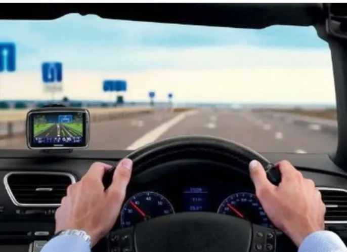
Generally, head down display (HDD)-based land vehicular navigation systems have been used. This may cause obscuring the view when a driver watches the navigation monitor as shown in Fig. 1, that is traffic accident rate increases. On the other hand, head up display (HUD)- based navigation system with AR-based contents can solve this problem as shown in Fig. 2a. With this motivation, recently, the HUD-based navigation system has been researched and developed for safety and convenience services (Park et al. 2013).
Another motivation for using the vehicular AR-HUD system can be found in Fig. 2b. In the fog, rain or night, it may be difficult to provide safe guidance service based on the conventional HDD-based navigation system. If additional lane information can be provided using the AR- based contents in these environments, safe driving can be achieved as shown in Fig. 2b.
3. INTEGRATED NAVIGATION SYSTEM FOR AR-BASED GUIDANCE SERVICES
For the safe guidance service as shown in Fig. 2, a camera/infrared-camera installed in a vehicle detects the lanes on the front road. Then, clear lane information can Fig. 1. A drawback of the HDD-based navigation system.
Fig. 2. Usefulness of the HUD-based navigation system. (a) general navigation service (b) safety service using the AR-based contents.
(a)
(b)
be displayed on the HUD system. However, the camera- based lane detection has a limit in the bad environments.
If a navigation system provides accurate lane-level position and heading information, virtual lane information can be generated by combining the accurate navigation solution and digital map information. Fig. 3 shows an example of HUD-based navigation service with AR-based contents.
The displayed contents can give a driver convenient information. However, the contents also may give a driver the visual obstruction owing to the mismatching on the lanes.
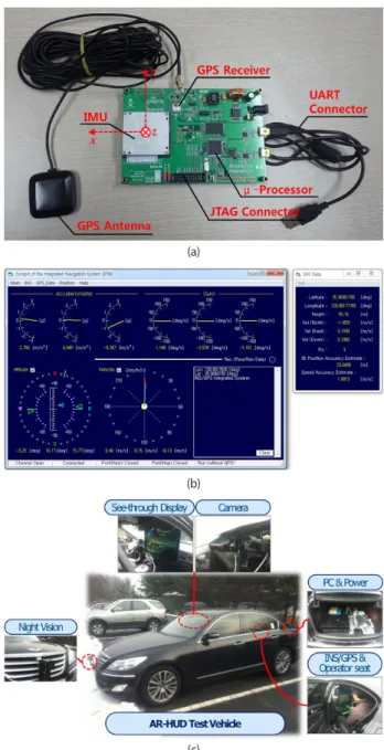
In this paper, an integrated navigation system that provides accurate navigation solution and several accurate status information of a land vehicle is presented to solve the problem. The hardware and software system structure for the integrated navigation system is designed as Fig. 4. The system consists of a main computer, INS/GPS navigation system, and camera. In the main computer, four s/w blocks – main s/w, control & monitoring s/w, vision processing, and digital map – have interactive relations. The INS/
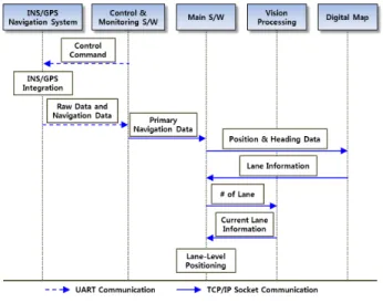
GPS navigation system consists of an IMU, a GPS receiver, and a μ-processor. The μ-processor generates primary navigation solutions by integrating the IMU data and GPS measurements. The camera output is processed in the vision processing s/w block. The main s/w controls the data interface among the INS/GPS navigation system, vision processing and digital map as shown in Fig. 5. The data call flow can be explained as following procedure.
First, INS/GPS-based navigation data is generated in the INS/GPS navigation system periodically after receiving the control command from the control & monitoring s/w.
The navigation data consists of position, velocity, attitude, heading, and status information of the vehicle containing the navigation system. The navigation data and IMU raw data is transferred to the control & monitoring s/w using the UART communication. The IMU raw data is saved as computer file and then, the primary navigation data is transferred to the main s/w using the TCP/IP socket communication. The main s/w transfers the position and heading data to the digital map block. The digital map generates lane information based on the position and heading data. The lane information contains the number of lanes of current driving road, map-matched position data, and lane width. The lane information is transferred to the main s/w. After receiving the lane information, the main s/
w transfers the number of lanes of current driving road to the vision processing block. The vision processing block detects lanes using the output of the front camera. Based on the number of lanes and the detected lane information, current lane number is decided. The decided current lane information is transferred to the main s/w. Then, lane- level positioning is processed in the main s/w based on the primary navigation data transferred from the INS/GPS navigation system, the lane information transferred from Fig. 3. Mismatch between AR-based contents and road in a HUD-based
navigation system.
Fig. 5. Data interface.
Fig. 4. System structure for the INS/GPS/vision/digital map integrated
navigation system.
the digital map block, and the current lane information transferred from the vision processing block as shown in Fig. 6. In this figure, Pos
P, Pos
MM, and Pos
LLindicate the primary position, map-matched position, and lane-level position, respectively. Finally, the main s/w provides the navigation solution for providing lane-level position-based services such as lane-level guidance service.
4. IMPLEMENTATION OF THE IGVM INTEGRATED NAVIGATION SYSTEM
In this section, the IGVM integrated navigation system was implemented. The INS/GPS navigation system consists of an IMU, a GPS receiver and a μ-processor. ADIS16375 (Analog Devices, Inc.) 6-degree of freedom IMU, u-Blox 6 GPS module (u-Blox, Inc.), and STM32F103 containing ARM 32-bit CortexTM- M3 CPU (STMicroelectronics, Inc.) were used to implement the INS/GPS navigation system as shown in Fig. 7a. JTAG connector was used to embed the compiled firmware in the μ-processor and UART connector was used to connect the INS/GPS navigation system to the control & monitoring s/w as shown in Fig. 7b. The control
& monitoring s/w can operate the navigation system and also can display various information (IMU raw data, GPS information, vehicle status, navigation solutions, etc.) transferred from the INS/GPS navigation system. The GUI- based control & monitoring s/w was made in this work using the visual basic 6.0.
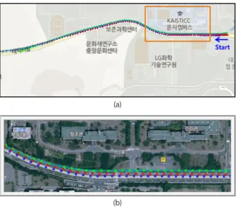
Fig. 7c shows the implemented AR-HUD test vehicle containing the integrated navigation system. In this system, INS/GPS navigation system was fixed down in the center of the vehicle (x, y, and z-axes are aligned with the forward, right lateral, and down directions of the vehicle), the camera and night vision were installed in front of the vehicle, and
the digital map was installed in the PC. The camera and night vision are used for detecting the lanes in day and night hours, respectively. The control & monitoring s/w was played on the on-board main computer of the vehicle. The IMU raw data and GPS measurements as well as navigation solutions were saved in the computer through the control
& monitoring s/w for performing the post-processing with other filters.
4.1 INS/GPS Integration
The INS and GPS solutions are integrated loosely using Fig. 6. Concept of the lane-level positioning.
Fig. 7. Implemented system. (a) INS/GPS H/W (b) control & monitoring S/
W (c) AR-HUD test vehicle containing the integrated navigation system.
(a)
(b)
(c)
the extended Kalman filter (EKF)-based multi-model switching filter that consists of three system models for run with GPS measurement, run without GPS measurement, and stop.
First, the condition of the GPS measurement is examined.
The GPS measurements are obtained based on UBX protocol. NAV-SOL (navigation solution information) is checked. In the payload contents, if gpsFix is0x03 and pAcc is smaller than δ
GPS, the GPS solution is decided to be used. Where gpsFix (0x00: No Fix, 0x02: 2D-Fix, and 0x03:
3D-Fix) and pAcc (3D position accuracy estimate, cm) are parameters for checking the GPS signal status obtained from the u-Blox GPS receiver. δ
GPSis the threshold for detecting the usability of the received GPS data and is determined heuristically.
Second, the vehicle status is determined based on the IMU output and velocity information. The following value is calculated using the IMU and GPS outputs.
k z
y x i
bk b i
k i
k
f f V
f = − +
∆ ∑
= −
,
, , , 1
, (1)
where f
i,kbis the output of the i-axis accelerometer at time k, and
= <
= ∑
∑
=
=
otherwise pAcc 03
0 gpsFix
, ,
, ,
D E N i
iINS
GPS D
E N i
iGPS
k
V
and x V
V
δ , (2)
where V
iINSand V
iGPSdenote velocity solutions obtained by the INS and GPS, respectively.
Using (1), the following value is calculated
+ ∆ <
=
−otherwise f Cnt
kstopCnt
kstop k INS0
1
1 δ
, (3)
where Cnt
0stopis set to zero.
If Cnt
0stopis larger than N
stop, it is decided that the vehicle status is stop at the current time. Otherwise, the following second condition is examined.
= <
= otherwise
pAcc 03
0 gpsFix status
vehicle
woG
GPS wG
moving
and x
moving
δ
, (4)
where moving means the vehicle is moving. The subscript wG means the GPS velocity information is reliable and woG means the opposite of wG.
The δ
INS, δ
GPS, and N
stopare the threshold for detecting vehicle stops and are determined experimentally. If the velocity term is excluded from (1), frequent false conditions can be generated when the vehicle runs with a constant velocity.
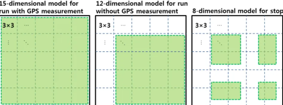
Based on the condition of the GPS measurement and vehicle status, a system model is selected in a filter. The reason of model switching is the change of the observability of the filter according to the available measurements.
If the vehicle status is moving
wG, a 15-dimensional model is used in the normal environments where GPS signal is available with 3D-fix and good accuracy. The state variables include position errors (δL, δl, δh : latitude error, longitude error and height error), velocity errors (δV
N, δV
E, δV
Din navigation frame), attitude errors (ϕ
N, ϕ
E, ϕ
Din navigation frame), accelerometer biases ( ∇
x, ∇
y, ∇
zin body frame) and gyro biases (ε
x, ε
y, ε
zin body frame). The system matrix with 15 × 15 dimension for EKF can be obtained in (Seo et al. 2006). The available measurement is the position and velocity information obtained from the GPS receiver. That is, the measurement model can be denoted as follows (Cho et al. 2007):
) , 0 (
~ , ] 0 [
] ) ( ) ( [ ] ) ( ) ( [
15 9 15
6 6
6
x v v N R
I
Vel Pos
Vel Pos
z
k k k
T T GPS k T GPS k T T INS k T INS k k
+
=
−
=
×
×
, (5)
where Pos
INSand Vel
INS≡ [V
NV
EV
D]
Tare position and velocity solutions in the INS, Pos
GPSand Vel
GPSare GPS measurements, x
15is the state vector of the 15-dimensional model and R
15is the measurement covariance matrix used for the 15-dimensional model-based EKF.
Fig. 8. System matrices and state error covariance matrices according to models.
If the vehicle status is moving
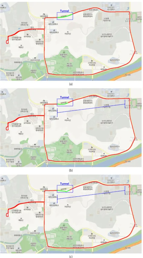
woG, a 12-dimensional model is used in the tunnel-like environments where GPS signal is not available. The state variables exclude the position errors from the 15-dimensional model. The system matrix with 12 × 12 dimension can be obtained from the system matrix with 15×15 dimension as shown in Fig. 8. The available measurement is the lateral & vertical velocity information in body frame based on the land vehicle dynamics with non-holonomic constraint (Shin 2001, Munguia 2014). The measurement model can be denoted as follows (Cho et al.
2007):
) , 0 (
~ ,
0 0 ]
0 0 [ )) 3 : 2 (:, (
12
12 3 1 23 13 33 13 33 23 33 23 13
3 1 22 12 23 12 23 22 23 22 12
R N v v
V x c V c V c V c V c V c c c c
V c V c V c V c V c V c c c c
Vel C
z
k k
k N E N D E D
N E N D E D
T kINS T bn k
+
+
−
− +
−
+
−
− +
= −
−
=
×
×
, (6)
where c
ijis the components of the direction cosine matrix (C
bn) of the vehicle attitude calculated in the INS, x
12is the state vector of the 12-dimensional model and R
12is the measurement covariance matrix used for the 12-dimensional model-based EKF.
If the vehicle stops, an 8-dimensional model is used.
The state variables include velocity errors ( δV
N, δV
E, δV
D), attitude errors (ϕ
N, ϕ
E), accelerometer bias ( ∇
z) and gyro bias (ε
x, ε
y). The system matrix with 8×8 dimension can be obtained based on the selected state variables as shown in Fig. 8. The available measurement is the zero velocity information of the vehicle. That is, the measurement model can be denoted as follows (Cho et al. 2007):
) , 0 (
~ , ] 0 [
] 0 0 0 [
8 5 8
3 3
3
x v v N R
I V z
k k k
T kINS
k
+
=
−
=
×
×
, (7)
where x
8is the state vector of the 8-dimensional model and R
8is the measurement covariance matrix used for the 8-dimensional model-based EKF.
The state error covariance matrices as well as the system matrices for the 12-dimensional and 8-dimensional models can be used by extracting from the 15-dimensional model as denoted in Fig. 8. One more important thing is resetting of the state error covariance matrix when the system model is changed. There are two special cases. In the first case:
the GPS signal becomes to be available when the vehicle gets out of a tunnel. In this case, the 12-dimensional model is changed to the 15-dimensional model. If the duration of the GPS signal outage time is over than 10 seconds, the diagonal terms in the state error covariance matrix corresponding to the position errors, velocity errors and heading error must be reset to the initial values. The reason is that the estimation error of the heading error in the
12-dimensional model-based EKF may increase and the position and velocity errors are correlated with the heading error. Also the off-diagonal terms must be reset to 0. In the second case: the vehicle starts from stationary state. That is, the 8-dimensional model is changed to 15-dimensional or 12-dimensional model. One thing to do in this case is reset the off-diagonal terms to 0. In the other cases, the covariance matrix itself is used.
4.2 IGVM Integration
The position data provided by the INS/GPS navigation system is used the primary position for lane-level positioning based on the IGVM integration.
T kP kP kP
kP
Lat Lon Hgt
Pos = [ ] , (8)
where Lat
P, Lon
P, and Hgt
Pdenote the latitude, longitude, and height calculated in the INS/GPS navigation system.
Based on the primary position, the lane information is obtained from the digital map and vision as shown in Fig. 5.
The lane information contains the map-matched position as shown in Fig. 6. Then, the lane-level positioning is processed as follows:
( )
( ) ( )
⋅
−
⋅
⋅
−
⋅ +
=
0
cos / sin ) 5 . 0 (
/ cos ) 5 . 0 (
P k t k k k
L
km k L k
M M k LL
k
W n R Lat
R n
W Pos
Pos ψ
ψ
, (9)
where Pos
MMis the map-matched position calculated in the digital map using the primary position data Pos
P. In general digital map, the position data is matched on the center lane of the road. Pos
LLis the calculated lane-level position data, W
Lis the land width, n is the current lane number, and ψ is the heading calculated in the INS/GPS navigation system.
R
mand R
tare calculated as (Seo et al. 2006)
3 2 2 2
0
( 1 ) / ( 1 sin
kP)
m
k
R e e Lat
R = − − , (10)
P k t
k
![Fig. 10. Vehicle status decision. (a) GPS measurements (b) expanded figure of time section [230 270] in Figure (a) (c) Δf & decided filter dimension (d) Δf'.](https://thumb-ap.123doks.com/thumbv2/123dokinfo/5263900.632289/7.892.188.698.200.841/vehicle-decision-measurements-expanded-section-figure-decided-dimension.webp)