선수 타 주위 유동의 수치적 해석
구본국1*, 박준모2
1창원대학교 조선해양공학과, 2동명대학교 전자및의용공학부
Numerical Analysis of Flow around Bow Rudder
Bon-Guk Koo1*, Jun-Mo Park2
1Department of Naval Architecture and Marine Engineering, Changwon National University
2School of Electronic and Biomedical Engineering, Tongmyong University
요 약 본 연구는 선박의 조종성능에 직접 영향을 미치는 방향타의 양력, 항력 및 모멘트를 전산유체역학을 이용하여 연구하 였다. 힘과 모멘트에 영향을 미치는 전형적인 선박 방향타 중 하나는 바다에서 조종하는 동안 선수 타이다. 따라서 선박 선수 타에 대한 힘과 모멘트를 연구하였다. IFS 선수 타 시리즈 중 균형 IFS 54 BR 15는 연구에 사용되었다. 난류 모델로는 표준 k-epsilon이 연구에 적용되었다. 선수 타의 유체 역학, 특히 양력, 항력 및 모멘트 계수는 서로 다른 공격 각도에 대해 계산되었 다. 본 연구에 사용된 유동과 선수 타 사이의 받침각은 0도에서 5도 간격씩 35도까지 총 6개이다. 선박의 운동 성능에 미치는 영향에 대한 계산 결과는 이전 실험 연구 결과와 비교되었다.
• 주제어 : 선수 타, 전산유체역학, IFS 54 BR 15 타, 수치해석, 받음각
Abstract In this study, the lift, drag and moments of the rudder that influences on the maneuvering ships directly has been investigated using CFD(Computational Fluid Dynamics). One of typical ship rudders effecting on the forces and moments is the bow rudders during maneuvering on the sea. Thus, the forces and moments should be investigated for the bow of ship rudder. Among the IFS bow rudder series, the balance IFS 54 BR 15 is used for study. As a turbulent model, standard k-epsilon is applied to this study. The hydrodynamic of the bow rudder, especially lift, drag and moment coefficients are calculated for the different angles of attack. The angles of attack between water flow and rudder are presented in cases including 0°, 5°, 10°, 15°, 20°, 25°, 30° and 35°. The results of calculation for those influences on maneuvering performance of ships are compared with the relevant results of the previous experimental studies.
• Key Words : Bow rudder, CFD, IFS 54 BR 15 Rudder, Numerical analysis, Angle of attack
Received 17 December 2020, Revised 22 December 2020, Accepted 28 December 2020
* Corresponding Author Bonguk Koo, Department of Naval Architecture and Marine Engineering, Changwon National University, Changwon, Korea. E-mail: [email protected]
Ⅰ. 서론
The ship improvement in maneuvering performance is interested in the ship engineering field. There are many studies to determine the response of a ship in maneuvering. To make a ship to operate on the sea efficiently and smoothly, it must achieve suitable forces and moments from its rudder. The study of Lui et al.(2016) reviewed impacts of the rudder profile on maneuvering performance of the classic NACA and the IFS series.
The hydrodynamic of control surface for ship maneuvering was investigated with experiments numerical simulations[2-5]. To ready for the comparison of rudder forces and moments among some different rudders and operating in different speeds condition, non-dimensional form is a great choice to do that.
The followings are the non-dimensional forms of the rudder forces and moments that are commonly used[3]:
Lift coefficient:
Drag coefficient:
Moment (torque) coefficient about the rudder stock:
where , , is density, the rudder inflow velocity and the profile area respectively. In this study, using computational fluid dynamics(CFD) to calculate for the bow rudder is static in moving flow environment.
Ⅱ. Rudder used in simulations 2.1 Rudder geometry
There are various rudders having different geometry and also have different hydrodynamics.
From a rudder sections the IFS 54 BR 15 is chosen to
build real rudder and investigate its hydrodynamics.
2.2 Rudder geometry
The IFS series section have some advantages such as the maximum lift coefficient increasing be-cause of the optimization of the pressure distribution. Thieme (1965) described about the experimental results of IFS series and also presented IFS 54 BR 15 rudder profile.
2.3 Section of rudder
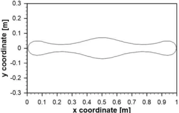
The IFS 54 BR 15 rudder[6] is one of the rudders that achieves a high efficiency. Its profile is used for several types of ships and the x coordinate and y coordinate of the IFS 54 BR 15 rudder is shown in Fig. 1.
Fig. 1. IFS 54 BR 15 rudder profile
2.4 IFS 54 BR 15 rudder
The IFS 54 BR 15 rudder is created by 3D CAD which is shown in Fig. 2, and it is applied in the CFD simulations.
Fig. 2. IFS 54 BR 15 rubber model
Ⅲ. Numerical modelling
3.1 Computational domain and boundary condition
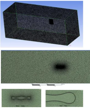
The square domain is used for this computation. In this study, the bow rudder is located in the three-dimensional square domain covering the area as shown in Fig. 3. The length and height of the rudder are 1m, 1.5m respectively. The square domain is determined by the length of 15CR, the height of 7.5CR
and the width of 6CR in which CR is a mean chord.
In this case, there is a root chord, a tip chord and a mean chord that are the same dimension. Fig. 3 shows that velocity inlet is applied in the x direction and symmetry is defined in side surfaces and the pressure outlet is assumed in after surface.
Fig. 3. Three-dimensional square domain and boundary condition
3.2 Mesh generation
One of important steps is to make the mesh sufficiently to reach reliable computational process us-ing CFD. So in this paper, the hybrid mesh is generated with inflation structured to ensure qualify of computation.
The incompressible is defined during computational process. The velocity of water flow passing to the rudder is 10m/s and the Reynolds number can be inferred from the flow velocity. Fig. 4 describes the mesh for the IFS 54 BR 15 rudder.
Fig. 4. Mesh structure
3.3 Governing equations
The governing equations are continuity and RANS (Reynolds Averaged Navier-Stokes) equations as presented below:
(1)
′′
(2)
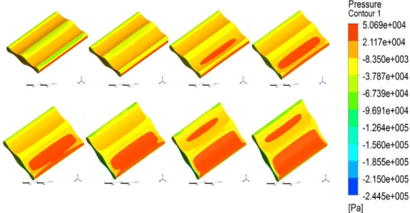
Fig. 5. Pressure distribution at different angle of attack form 0〫to 35〫(from top right to bottom left)
(a) (b)
(c) (d)
(e) (f)
(g) (h)
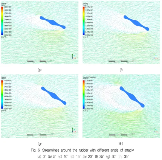
Fig. 6. Streamlines around the rudder with different angle of attack:
(a) 0〫(b) 5〫(c) 10〫(d) 15〫(e) 20〫(f) 25〫(g) 30〫(h) 35〫
Ⅳ. Simulation results
The pressure contour and streamlines on the IFS 54 BR 15 rudder is investigated for various attack angles. Fig. 5 shows the effect of pressure on IFS 54 BR 15 rudder corresponding to various different attack angles, especially the pressure distribution around the rudder. As the attack angles increase from 0°to 35°, it causes the higher pressure effect. The streamline distribution around the rudder is shown in Fig. 6.
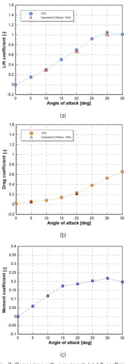
The lift, drag coefficient compared with experimental results, and moment coefficient corresponding to angle of attacks are described in Fig.
7. The lift coefficient maximizes at approximate
30°and the similar trend is shown for moment coefficient. The drag angle tends to increase in the angle of attack increase.
(a)
(b)
(c)
Fig. 7. Comparison with experiment; (a) Lift coefficient (b) Drag coefficient (c) Moment coefficient of the IFS 54
BR 15 rudder
Ⅴ. Conclusions
In this study the effect of flow on the IFS 54 BR 15 rudder is investigated without the propeller and
the ship hull using numerical simulations. Pressure contours and streamlines distribution corresponding to the angle of attacks are presented.
The lift, drag and moment coefficient are also presented to show the interaction between the IFS 54 BR 15 rudder and flow field. This is the one of important aspects of selection and calculation for rudder which is considered to be suitable for ship maneuverability. The lift and drag coefficient are compared with the experimental results performed by Thieme(1965).
ACKNOWLEDGMENTS
이 논문은 2019-2020년도 창원대학교 자율연구 과제 연구비 지원으로 수행된 연구 결과임.
REFERENCES
[1] J. Liu, R. Hekkenberg, F. Quadvlieg, “Impacts of the rudder profile on maneuvering performance of ships,”
Ocean Eng., vol. 124, pp. 226-240, 2016.
[2] V. L. Edward, “Principle of naval architecture, Volume III: Motions in waves and controllability,” The Society of Naval Architects and Marine Engineers, 1989.
[3] Y. Ozdemir, S. Bayraktar, T. Yilmaz, “Flow field analysis of a rudder by using computational fluid dynamics,” 5th International Advanced Technologies Symposium (IATS'09), 2009.
[4] P. Lu, S. Wang, “Investigation of ventilation and current effect of tunnel thruster for DP applications,”
Proceedings of the ASME 2015 34th International Conference on Ocean, Offshore and Arctic Engineering, Canada, 2015.
[5] L. J. L. Beveridge, “Design and performance of bow thrusters,” Naval Ship Research and Development Center, 1971.
[6] H. Thieme, “Design of ship rudders,” Shipbuilding Institute University of Hamburg, 1965.
저자 소개
구 본 국 (Bon-Guk Koo)
2002년 2월 : 부산대학교
조선해양공학과(공학사)
2004년 2월 : 부산대학교
조선해양공학과(공학석사)
2006년 5월 : UCLA
기계공학과(공학석사)
2011년 5월 : Univ. of Iowa
기계공학과(공학박사)
2014년 3월~현재 : 창원대학교 조선해양공학과 교수
관심 분야 : 유동해석/전산유체역학
박 준 모 (Jun-Mo Park)
1993년 2월 : 인제대학교
의용공학과(공학사)
1996년 2월 : 인제대학교
의용공학과(공학석사)
2008년 8월 : 부산대학교
의공학협동과정(공학박사)
2018년~현재 : 동명대학교 전자및의용공학부 교수
관심 분야 : 신호처리, 뇌 신경계 신호 분석