학술논문 지상무기 부문
임무계획 및 전역경로계획에 기반한 무인전투차량의 운용자 인터페이스 구현
User Interface for Unmanned Combat Vehicle Based on Mission Planning and Global Path Planning
이 호 주* 이 영 일* 박 용 운*
Ho-Joo Lee Young-il Lee Yong-Woon Park
Abstract
In this paper, a new user interface for unmanned combat vehicle(UCV) is developed based on the mission planning and global path planning. In order to complete a tactical mission given to an UCV, it is essential to design an effective interface scheme between human and UCV considering changing combat environment and characteristics of the mission. The user interface is mainly composed of two parts, mission planning and global path planning, since they are important factors to accomplish combat missions. Frist of all, mission types of UCV are identified. Based on mission types, the concept of mission planning for UCVs is presented. Then a new method for global path planning is devised. It is capable of dealing with multiple grid maps to consider various combat factors so that paths suitable for the mission be generated. By combining these two, a user interface method is suggested. It is partially implemented in the Dog-horse Robot of ADD and its effectiveness is verified.
Keywords : Robot(로봇), Unmanned Combat Vehicle(무인전투차량), User Interface(운용자 인터페이스), Global Path Planning(전역경로계획), Mission Planning(임무계획)
1. Introduction
Future war, rather than focusing on individual platform, is transforming to NCW(Network Centric Warfare) using decentralized strength of far-distance and asymmetry spanning over 5 dimensional battlefield; ground, air, sea,
†2009년 8월 5일 접수~2009년 11월 13일 게재승인
* 국방과학연구소(ADD)
책임저자 : 이영일([email protected])
cyber and space. Recently Korean Army considers unmanned combat system as one of future defense strategies as result of reflecting advanced technology and serious attention on human life. Such tendency also can be seen in the ‘Required Capability Statement of Joint Concept’ prepared by Joint Staffs of Staff and ‘Detail Concept of Unmanned Combat’ by the Army. This complies with the changing aspect of conducting war like NCW.
According to the Required capability statement of joint
concept, unmanned system can maximize the operation effect of manned system by performing complementary cooperation as an auxiliary measure helping the manned system. This can be checked by the definition of unmanned system either described as ‘combined system integrating manned system and unmanned equipment to supplement the human centric combat system’[1].
Among various unmanned systems, unmaned combat vehicle(UCV) such as ‘Multi Purpose Dog-Horse Robot (to be called Dog-horse robot)’, a prototype developed by a robot technology R&D project of ADD(Agency for Defense Development), is in the center of attention.
Currently, some UCVs are reviewed as new requirements to be included in the defense planning document as well.
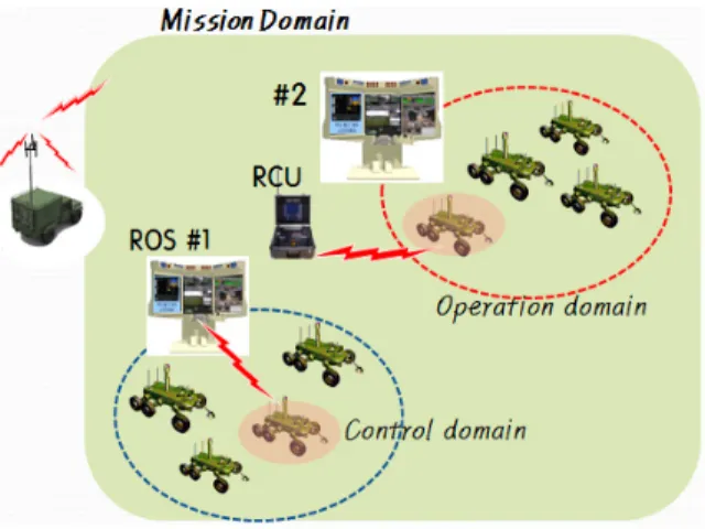
To operate a UCV, an effective user interface between human and UCV should be developed based on the doctrines and operational concepts. The operational concept of Dog-horse robot is the NMAC[2](N-operators M-robots Access Control) as shown in Fig. 1. It means that 1∼2 operators operate multiple robots via remote control stations such as RMS(Remote Mission Station), ROS(Remote Operation Station) and RCU(Remote Control Unit).
Fig. 1. Depict of NMAC
There are several issues to consider for the implementation of NMAC. First of all, the problem of
‘How to fulfill a given mission by using which robot through remote control or autonomous navigation?’
needs to be solved first. For this, an effective interface scheme including menu and GUI(Graphic User Interface) must be devised in the operation system.
In this paper, it is suggested an user interface scheme for UCV, which is based on the mission planning and global path planning. To develop the user interface, related components are explained in chapter 2. In chapter 3 an experimental realization of the user interface is given with the implementation concept. Finally, chapter 4 is for the concluding remarks.
2. Components of the user interface
To develop an user interface for UCV, there are two important components to consider; mission planning(MP) and global path planning(GPP). MP is the process of the embodiment of how to operate one or multiple UCVs in order to accomplish given combat missions. For the execution of MP, it is necessary to identify what kinds of mission can be carried out by UCV. In other words, mission types of UCV should be defined first.
GPP is planning a movement/maneuver path for UCV to perform a mission. Path following can be done by either remote control or autonomous navigation. Path can be designated by operator or optimized by artificial intelligence to be suitable for executing the mission.
Details of mission types of UCV, mission planning and global path planning are explained further.
2.1 Identification of mission types of UCV Mission types of UCV can be identified by considering the purpose of operation, capability, method/process of control, etc. in overall. In case of Dog-horse robot, it is capable of doing surveillance/security using a image acquisition equipment of 10km ahead via remote operation within 5∼6km LOS(line of sight). In addition, other types of missions such as mine detection using mine detector mounted on the vehicle, limited light combat with the machine gun are possible. If necessary, Dog-horse robot can navigate without intervention of operator to perform given missions through the localization and world modeling. World modeling is the
perception of surrounding environment including the configuration of the ground.
In consequence, it can be identified mission types of UCV as {maneuver, surveillance/security, mine detection, stand-by} by referring to Dog-horse robot. Moreover, by combining whether or not operating arm and the status of movement/stop of the vehicle more concrete classification of the mission type is possible. The operation of arm is applicable to all mission types. On the other hand, the status of movement/stop needs to be considered for only two mission types; surveillance/
security and stand-by because maneuver and mine detection are carried out under movement status only.
Mission types become the basis for designing the menu system and GUI for operating UCVs. In other words, mission planning such as setting a mission scenario that is a bundle of missions ordered in time sequence and issuing any fragmentary command to UCV starts from selecting one of mission types
2.2 Mission Planning
Mission planning is a prime problem for the operator to solve with direct involvement before considering any other problems; collision avoidance, vehicle stability and local path planning, which are dealt by vehicle itself.
For the operation of manned systems and/or soldiers, mission planning is carried out by a leader/commander based on his experience and intuition. However, it is not
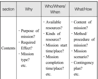
Table 1. Elements of MP problem
section Why Who/Where/
When What/How
Contents
․Purpose of mission?
․Required Effect?
․Mission type?
etc.
․Available resources?
․Kinds of resource?
․Mission start time/place?
․Mission completion time/place?
etc.
․Content of mission?
․Method/
procedure of mission?
․Mission scenario?
․Contingency plan?
etc.
human anymore to be the object directly involved in combat activities. Thus there arises questions on whether or not the existing procedure of mission planning is still effective for UCV. To understand the problem of mission planning(MP problem) clearly, its elements need to be considered are shown in Table 1.
To solve the MP problem in a systematic manner, it is necessary to devise a symbolic or logical language for the description of it on the user interface of UCV.
Elements of the MP problem in the table are categorized into two terms; object and event terms, as below.
Object terms :
Who = {R} R: Robot(UCV) Where = {S, P, G}
S: start point, P: mission point, G: Goal point When = {T} T: time
Event terms :
What = {Mv, Ss, Mt, Sb, ...}
Mv: maneuver, Ss: Surveillance/security, Md: mine detect, Sb: stand-by
How = {sub modes of every 'what' term}
In addition, to use the terms a gramma is defined as below.
What[Who, Where, How(optional)]T →
What[Who, Where, How(optional)]T (1)
For example, it is supposed that a platoon is given a mission as below. Then the statement of the MP problem can be described as (2)∼(4) according to the terms and format.
Mission :
* Assumption : a platoon leader operates 4 UCVs.
① Platoon starts its mission at 10:00 and arrives in P#1 by 11:00. Then watch and collect information.
② To secure the route for its battalion, detect mines at P#2 from 14:00 to on-order.
③ Stand-by at P#3 untill on-order and return to the assembly area P#4 by 20:00.
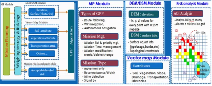
Fig. 2. GPP architecture MP problem :
Ma[R1∨R2∨R3∨R4, P1]10:00∼11:00 →
Ss[R1∨R2∨R3∨R4, P1, intensive mode]11:00∼ (2) Ma[R1∨R2∨R3∨R4, P2]∼14:00 →
Md[R1∨R2∨R3∨R4, P2, Speedy mode]14:00∼On-order (3) Sb[R1∨R2∨R3∨R4, P3]TBD →
Ma[R1∧R2∧R3∧R4, P4]∼20:00 (4)
Acronyms used in the descript, Mv, Ss, Md, Sb, mean maneuver, surveillance/security, mine detection and stand -by, respectively. These are the mission types of UCV as identified earlier. R denotes Robot(UCV) and symbols
∨ and ∧ mean ‘or’ and ‘and’.
The purpose of defining and describing MP problem as above is to find the answer of how to operate UCVs in the manner of rational & scientific so that given missions be accomplished efficiently. MP problem brings up another optimization problem of which characteristics is similar to the scheduling problem, thus its solution can be found without much effort by using available solution methods It is important to assure that all the components of MP problem are included in the user interface of UCV.
2.3 Global Path Planning
There is a close connection between GPP and user interface of UCV. It is because that mission types,
maneuver, surveillance/security, mine detection and stand-by can be carried out under movement as well as standstill. Thus a mission type selected by the operator needs any movement, GPP should be launched instantly.
Types of GPP can be classified into three considering the level of involvement of operator and time and spacial constraints applied. They are route following that whole path is marked by operator, waypoint navigation in which some points of passing through or performing mission are designated by operator and autonomous navigation where only start/goal points are given then path is optimized by artificial intelligence. Among them, autonomous navigation is capable of considering combat circumstances and various combat influence factors in the generation of paths. In order to design GPP in the user interface, GPP is explained in detail.
To execute GPP, grid maps of target area(AOI : Area of Interest) for path planning should be prepared first as input data[3~6]. Various information such as velocity, level of enemy threat, communication and logistics capacity can be considered into a gird map in which information is inputted in the form of numerical value in the cells. Procedure and components of GPP can be checked in Fig. 2. An optimization algorithm is required to execute GPP of autonomous navigation. Among available algorithms such as Dijkstra, A* and D*, A* is regarded as practical because it is easy to implement
and gives optimal paths within short computation time.
In the path search process, traverse time of the vehicle along the path is critical one to consider.
Therefore, the cost function of GPP algorithm of A* needs to be transformed into time unit using equation (5)∼(6). Total cost f(n) is composed of two parts, g(n) and h(n). g(n) is the traverse time from the starting point(grid) to nth grid and h(n) is the estimated traverse time from nth grid to the goal point.
(5)
(6)
Notations Vn, dn-g and ΔG are used to denote the velocity of grid n, distance between grid n and the goal point and grid size, respectively. The traverse time over the current gird is computed as dividing the gird size by the velocity corresponding to the gird. It is the estimated traverse time that the distance between the current grid and goal point is divided by the average velocity of whole grids.
If multiple grid maps are used simultaneously, then cost functions are linearly combined[7] and normalized in order to find a global path on which user requirements are properly reflected. Thus the path becomes more suitable for carrying out a mission. Let P={1, 2,..., p}
be the grids of the path to be optimized. Then GPP, for example, using three gird maps can be defined as equations (7)∼(8). Constants for linear combination and normalization are denoted by α and δ, respectively.
min
(7)
≤for
≤
(8)
Operator can select constraints to reflect on the path.
For example, as shown in equation (8) the cost() of each grid included in the path should be smaller than the acceptable upper bound(R) and total traverse time must not exceed the limit(). Here the cost can be defined according to operator's interests such as level of enemy threat, communication/logistics capability, etc.
Another approach for handling GPP is to maximize the survivability of UCV along the path. The risk (probability of killed) over the path P, r(P), can be defined as equation (9) using , the probability that UCV is killed at ith grid of the path.
(9)
Consequently, the path for UCV to maximize its survivability can be found by solving below optimization problem.
min (10)
≤ (11)
To execute GPP(autonomous navigation), grid maps representing AOI should be prepared in advance. Since the grid size determines the complexity of the GPP problem, it needs to be chosen properly. By considering the sensing range of sensors for LPP(Local Path Planning) and the expected echelon under which UCVs are operated, it seems rational the grid size belongs to the range of 50∼200m. All activities related to generate a grid map such as designation of AOI, selection of grid map(s), determination of grid size and whether or not multiple gird maps are used should be included in the user interface for UCV.
3. Experimental realization
A path needs to be specified for UCV to carry out a mission after its mission type is designated by operator.
For this, in the user interface GPP should be combined
with each mission type and various constraints should be handled so that specific requests of the operator be properly reflected on the path. It is shown in Fig. 3 the concept of implementing MP by combining mission type and GPP, where relations of constraints according to each type of GPP is conceptually depicted as well.
(a)
(b)
Fig. 3. Concept of MP via combination of mission type and GPP with constraints
GPP can be executed for all types of mission as shown in Fig. 3-(a), On the other hand, constraints are differently applicable according to the type of GPP as depicted in Fig. 3-(b). For instance, either speedy navigation(‘speedy’ in the figure) to minimize traverse time or designation of velocity(‘designated V’) is possible for the types; route following and waypoint navigation.
However, other constraints such as enemy's threat and level of logistics/communication cannot be considered since the path is already designated by the operator.
Various constraints, however, can be handled in case of autonomous navigation. Suppose that mission type of surveillance/security is designated to a certain UCV and it tries to avoid as much risk(observation and firing by enemy) as possible, but still wants to maneuver quickly.
Then such condition can be solved by generating a path using another gird map of risk related as well as velocity map. Multiple gird maps based GPP makes it
possible to find paths suitable for a mission, that is, mission oriented path generation.
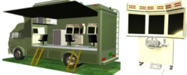
Fig. 4. Remote control stations of Dog-horse robot
The basic ability of NMAC, which is the operational concept of Dog-horse robot, is to allocate operational authority of UCVs to specific control stations. Using a RMS(Remote Mission Station) and two ROS(Remote Operation Station) as shown in Fig. 4, even 8 UCVs can be remotely operated at the same time. First of all, RMS allocates UCVs to ROS or RCU(Remote Control Unit) through the window of 'designation of operational authority' as shown in Fig. 5.
Fig. 5. Allocation of operational authority
After the operational authority is allocated, misson planning can be done through RMS and/or ROS.
Operator designates one of mission types to an UCV then all operational modes are adjusted automatically according to the mission type. Such related actions are done through the window of Fig. 6, which is triggered by the button of ‘mission planning’ available on both
Fig. 6. User interface for MP & GPP
RMS and ROS.
If GPP is required further after designation of mission type, then operator selects the type of GPP through the window of Fig. 6 and various constraints can be considered if necessary. Note that the interface for GPP is specialized for each mission type in order to reflect characteristics/difference of missions effectively.
As shown earlier in Fig. 3, constraints are applied differently according to the type of GPP. For the types of route following and waypoint navigation, velocity can be set as wanted but other constraints like risk or reducing traverse time by changing path are not considerable since the path is designated already by operator. Thus the interface window for such constraints becomes inactive. If autonomous navigation is selected, activated is the GPP interface window in which start/
goal points can be marked on the situation map and input boxes for constraints are available.
Contents of MP made by a certain RMS/ROS are shared to all control stations. If GPP is executed for certain UCVs, its content are shared too and can be displayed on ROS if it has the operational authority of the UCVs. Finally, ROS checks out the content of MP and transmits commands to UCVs.
A ROS operator can inquire and change the settings of operational modes which are automatically set perviously according to the mission type selected. This can be done through the interface(red dotted line) shown in Fig. 7. Also GPP can be adjusted by related buttons (yellow dotted line) by the ROS operator. These functions provide operators with flexibility by enhancing the ability to cope with changing and unexpected combat situation.
In addition, displaying various situation maps is
Fig. 7. Check/Change of operational modes and path planning
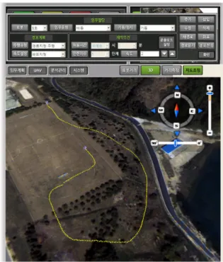
Fig. 8. Path designation on the situation map
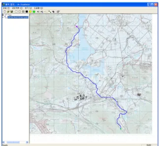
possible for all RMS/ROS, RCU and GPP module. By selecting a map suitable for a given mission, the situational awareness of the operator is maintained and enhanced. In particular, the interface for GPP being carried out on the situation map is essential for the effective operation of UCVs. For instance, operator designates a path on the map directly as shown in Fig.
8. Moreover, it is visualized on the military map, one of situation maps, a path optimized by GPP module.
Such interface is obviously helpful to monitor the progress of a mission in accordance with UCV's changing locations.
Fig. 9. Display of GPP result on the situation map
4. Conclusion
In this paper, a user interface is suggested based on the mission planning and global path planning for effective operation of unmanned combat vehicle(UCV).
Frist of all, mission types of UCV are identified and the concept of mission planning is developed. Then a method of global path planning using multiple gird maps is devised to optimize paths in manner of mission oriented in accordance with a selected mission type.
Also it is given an experimental user interface, which is
implemented on the Dog-horse robot of Agency for Defense Development.
The suggested scheme of the user interface is partially tested and its effectiveness is verified. However, concrete shapes for conducting mission planning including structurization of a mission scenario still remain for future research. In near future, it needs to be developed a real user interface which is simple, effective and user- centric for operating UCVs. This paper can be referred to develop a viable user interface.
Reference
[1] Joint Staffs of Staff, Required Capability Statement of Joint Concept, 2008.
[2] Kim, J., et al, “Design and Implementation of the NMAC in the Dog-Horse Robot System”, Proceedings of Korea Institute of Military Science and Technology Conference, pp. 1065~1068, 2007.
[3] Kramer, T. A., Laird, R. T., Dinh, M., Barngrover, C. M., Cruickshanks, J. R and Gilbreath, G. A., SPIE Unmanned Systems Technology VIII 2006.
[4] Giesbrecht, J., Global Path Planning for Unmanned Ground Vehicle, DRDC Suffield TM 2004-272, 2004.
[5] Thorpe, C., Hebert, M, Pomerleau, D., Stentz, A.
and Kanade, T., “Unmanned Ground Vehicle System Perception for Outdoor Navigation”, Technical Report TEC-0114, 1995.
[6] Stentz, A., “Optimal and Efficient Path Planning for Partially Known Environments”, Proceedings of IEEE International Conference on Robotics and Automation, 1994.
[7] Lee, H., et al, “Path Planning for Unmanned Combat Vehicle Considering Traverse Time and Risk”, Proceedings of Korea Institute of Military Science and Technology Conference, pp. 1027~1030, 2008.
[8] Lee, Y., et al, “Fuzzy Based Directional Grid Map for Local Path-Planning of Unmanned Ground Vehicle”, Proceedings of Korea Institute of Military Science and Technology Conference, pp. 1047~1050, 2008.