DOI: http://dx.doi.org/10.4313/JKEM.2015.28.8.544 ISSN 1226-7945 (Print), 2288-3258 (Online)
열전도성 플라스틱을 적용한 자동차 LED 전조등 방열구조 연구
김형진1,2, 이동규2, 박현정2, 양회석3, 나필선3, 곽준섭2,a
1 ㈜ 서광 부설연구소
2 순천대학교 대학원 인쇄전자공학과
3 (재)전남테크노파크 신소재기술산업지원화센터
Design and Fabrication of Heat Sink for Vehicle LED Headlamp Using Thermally-Conductive Plastics
Hyeong Jin Kim
1,2, Dong Kyu Lee
2, Hyun Jung Park
2, Hoe Seok Yang
3, Pil Sun Na
3, and Joon Seop Kwak
2,a1 Seo Gwang, Department of Research & Development, Jangseoung 515-862, Korea
2 Department of Printed Electronics Engineering, Sunchon National University, Suncheon 540-742, Korea
3 Jeonnam TechnoPark, Advanced Materials Industrializion Center, Suncheon 540-856, Korea
(Received June 25, 2015; Revised July 24, 2015; Accepted July 24, 2015)
Abstract: Since LEDs (light emitting diodes) have many advantages as a light source in vehicle headlamp, such as
good reliability, energy and space saving, and flexible headlamp design. On the other hand, the dependence of its performance and life on temperature have great influence on its practical use. In this study, design and fabrication of heat sink for vehicle LED headlamp were performed using thermally-conductive plastics. This study focused on the effective heat sink structure with limited space in the vehicle LED headlamp. We designed two different prototype of heat sink by thermal simulation using SolidWorks program, which had excellent temperature characteristics. The two different prototype of heat sink were fabricated by injection molding with thermally-conductive plastics. The results showed that LED Tj (junction temperature) of sample B (model 1) and sample C (model 1, 2) was below then 165℃ when applying the thermally-conductive plastics in heat sink of vehicle LED headlamp.Keywords: Light-emitting diodes, LED light, LED headlamp for vehicle, Heat sink
1. 서 론
자동차 전조등 광원은 1900년대에 최초로 텅스턴을
a. Corresponding author; [email protected] Copyright ©2015 KIEEME. All rights reserved.
This is an Open-Access article distributed under the terms of the Creative Commons Attribution Non-Commercial License (http://creativecommons.org/licenses/by-nc/3.0) which permits unrestricted non-commercial use, distribution, and reproduction in any medium, provided the original work is properly cited.
사용하고부터, 할로겐, HID (high intensity discharge)까지 많은 발전을 거듭해왔다 [1,2].
최근 LED는 친환경적, 반영구적인 수명 특성으로 인해 자동차 전조등에 적용하기 위한 많은 연구가 진 행되고 있다. 특히, 일본에서 최초로 양산 자동차에 LED 전조등 적용을 시작으로 유럽과 미국의 여러 자 동차사에서 적용을 하고 있다 [3-5].
자동차 전조등에 LED를 광원으로 사용할 경우, 기
존 광원에 비해 낮은 소비 전력을 사용하며 소형화와 경량화 설계가 가능해 자유도가 높은 디자인 설계와 에너지 절약효과를 얻을 수 있다. 자동차 전조등에 LED 광원이 성공적으로 적용되기 위해서는 방열설계 기술 및 방열 재료의 경량화가 요구된다. 자동차 LED 전조등은 자동차 엔진에서 발생하는 열과 라디에이터 등에서 발생하는 열로 인해 높은 온도에 노출되어 있 다. 이런 밀폐된 전조등의 내부에 배치된 LED 소자가 열화 되면 광량이 감소하고, 수명이 단축된다 [6]. 따 라서, 방열 구조 설계기술의 적용으로 열 저항 3 K/W 이하 수준의 방열 시스템이 필요하며, 방열핀, 방열팬, 적용에 따른 방열 시스템의 소재 경량화도 매우 중요 하다.
자동차 LED 전조등의 방열설계는 중요한 요소이며 방열성능이 우수하고 열전도도가 높은 금속재질을 heat sink로 사용하는 연구가 많이 진행되고 있으나 [7-9], 열전도도 특성이 우수한 플라스틱 수지를 이용 한 heat sink에 관한 연구는 미비한 실정이다.
본 논문에서는 SolidWorks 프로그램을 이용하여 자 동차 전조등의 제한적인 공간에 효과적인 방열구조를 가지는 heat sink의 방열설계 및 열 해석을 진행하였 다. 열 해석을 통하여 온도 특성과 사출성이 우수한 2 개의 모델을 기반으로 자동차 LED 전조등 heat sink 를 제작하였다. 열전도성 플라스틱을 사용한 자동차 LED 전조등 heat sink는 LED T
j가 165℃ 이하의 방 열 특성을 나타내었으며, 이는 자동차 LED 전조등에 열전도성 플라스틱 소재의 heat sink 적용이 가능함을 보여준다.
2. 실험 방법
2.1 자동차 LED 전조등 heat sink 구조
LED는 열에 취약하므로 이에 대한 대비가 중요하 며, 이는 소비전력과 수명과도 직결된다. LED 전조등 의 방열시스템에서 중요한 것은 heat sink의 구조설계 이다. LED에서 발생되는 열은 LED package → PCB
→ Thermal Interface Materials → Heat sink를 거 쳐서 최종적으로 대기로 방출된다. Heat sink는 외부 의 대류조건과 온도조건 등에 의해서 방열 성능이 크 게 좌우된다.
그림 1은 본 연구에서 적용한 자동차 LED 전조등의 heat sink 외각 크기로 폭 (Width) 50 mm , 깊이
Fig. 1. Schematic diagram of low beam module for Vehicle LED headlamp.
(Depth) 100 mm, 높이 (Height) 100 mm로 설정하 였고, LED 전조등을 일체형 heat sink 구조로 설계하 였다.
2.2 시뮬레이션 조건
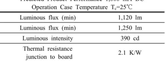
Table 1. Specification of LED.
Predicted Product Performance 1,000 mA DC Operation Case Temperature T
c=25℃
Luminous flux (min) 1,120 lm Luminous flux (min) 1,250 lm
Luminous intensity 390 cd
Thermal resistance
junction to board 2.1 K/W
Table 2. Parameters applied in simulation.
Model name Properties
Heat sink material Al 6063-T5
LED package power 12 W
Convection coefficient 5 W/m
2·K
Ambient temperature 105℃
LED 전조등은 방열시스템 공간이 제한적이며 국부 적으로 발생하는 열을 heat sink 구조 설계를 통해 LED T
j175℃ 이하로 관리해야지만 수명과 성능을 보 장할 수 있다. 본 논문에서는 LED T
j를 175℃의 6%
가량 감소시킨 약 165℃ 이하로 설정하였고, 사용된
LED package는 OSRAM사에서 개발된 자동차 전조등
용 고출력 백색 5칩 LED를 사용하였다 [10]. LED에 대한 제원은 표 1과 같다.
표 2는 열 해석에 적용된 재질 및 시뮬레이션 조건 을 나타내고 있다. 주변온도 378.15 K (약 105℃), 대류계수 5 W/m
2·K, LED 소비전력 12 W의 조건으 로 설정하였다. 모듈설계를 위해 3D PLM (Product Lifecycle Management) 도구인 SolidWorks를 사용 하여 설계하였고, 열 해석은 SolidWorks의 thermal simulation을 활용하였다.
2.3 자동차 LED 전조등 heat sink 제작 및 측정 방법
열전도성 플라스틱 (thermally-conductive plastics) 은 엔지니어링 플라스틱 (engineering plastics)의 한 종류로서, 열전도성이 우수한 플라스틱을 말하며 기존 플라스틱에 비해 5~100배까지 높은 열전도도를 가지고 있다. 열전도율이 다른 3종의 열전도성 플라스틱을 원 료를 가지고 자동차 LED 전조등 heat sink를 제작하 였다.
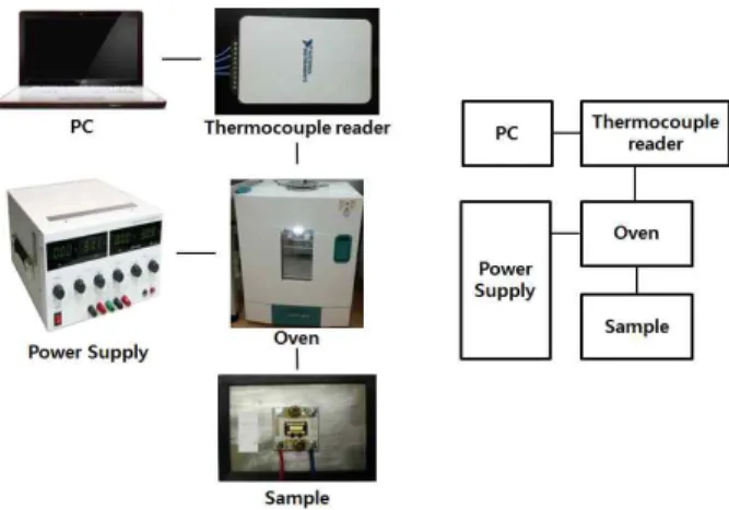
LED 전조등의 신뢰성을 증명하기 위해서는 혹독한 환경에서 테스트가 진행되어야 한다. 자동차 전조등은 혹서기 시 주위 환경의 온도는 약 40℃, 엔진 룸의 온 도는 약 90℃ 수준이다. LED 전조등의 방열 성능 평 가는 차량 엔진룸 보다 혹독한 환경을 조성하기 위해 서 오븐을 105℃로 설정하여 진행하였다. 자동차용 LED package에 소비전력 12 W를 공급 후 4개의 접 촉식 thermocouples를 이용하여 LED package의 soldering point, Al plate, heat sink의 방열핀, ambient temperature, 총 4군데를 측정하였다.
Fig. 2. Prototype measuring equipment and experimental diagram.
3. 결과 및 고찰
3.1 Heat sink 형상에 따른 시뮬레이션 결과
차량용 LED 전조등의 heat sink 구조 외각 사이즈 는 제한적인 공간으로 50×100×100 mm
3(W×D×H)로 설정하였다. Heat sink 형상은 총 4가지의 모델을 가 지고 열 해석을 진행하였다.
그림 3은 설계된 4가지 heat sink의 열 해석 결과 를 보여주고 있다. 열 해석 결과 rectangle 형상인 model 1의 heat sink가 다른 형상에 비해 177℃로 우수한 온도 특성을 보였다.
Fig. 3. Temperature contour of various heat sink model for ambient temperature at 105℃. (a) Temperature contour of various type of heat sink and (b) various shapes of heat sink used.
Model 1 Model 2 Model 3 Model 4 120
140 160 180 200 220
240 Temperature of LED chip surface
A re a o f d is s ip a tio n fi n (m m
2)
T e m p e ra tu re (
oC )
4x10⁴ 5x10⁴ 6x10⁴ 7x10⁴ 8x10⁴ 9x10⁴ Area of dissipation fin
Fig. 4. Various heat sink thermal simulation results at 105℃
and area of dissipation fin for each model.
그림 4는 여러 가지 형상들의 열 해석 결과와 방열
핀 면적을 그래프화 하여 비교하였다. Rectangle 형상
의 model 1의 방열 핀 면적이 95,594 mm
2으로 가장
넓었고, 차례대로 model 2는 56,968 mm
2, model 3
은 57,273 mm
2, model 4는 44,403 mm
2으로 측정되 었다. 최종으로 자동차 LED 전조등 heat sink의 sample 제작은 온도 특성과 사출성형이 우수한 model 1과 사출성이 우수한 model 2를 토대로 제작하였다.
3.2 자동차 LED 전조등 heat sink 제작 및 측정
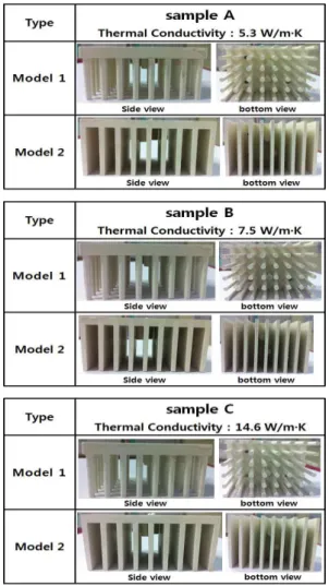
그림 5는 사출된 3종의 열전도성 플라스틱의 heat sink와 열전도율을 보여주고 있다.
Fig. 5. Three kinds of injection molding thermally-conductive plastics sample.
사출을 진행하기 전 열전도성 플라스틱은 80℃
oven에서 8시간 건조 후 사출하였다. 측정은 2.3절에 설명된 방법으로 접촉식 thermocouples를 사용하여 LED package의 soldering point 등 총 4군데를 측정
Fig. 6. The soldering point the injection molding sample.
0 5 10 15 20 25 30 35 40
100 110 120 130 140 150
160 @ room temperature
T e m p e ra tu re (
oC )
Time (min)
sample A sample B sample C (a)
Fig. 7. Soldering point temperature measurement for the various model 1 type heat sink.
하였다. 사출된 3종의 열전도성 플라스틱의 열전도도
Quick Line-10 열전도율 측정기를 이용하여 측정하였
다. 3종의 열전도성 플라스틱의 열전도도 측정 결과는
sample A―5.3 W/m·K, sample B―7.5 W/m·K,
sample C―14.6 W/m·K로 측정되었다. 그림 7(a)는
105℃ oven에서 model 1의 heat sink 온도 특성 결과와
0 5 10 15 20 25 30 35 40 100
110 120 130 140 150
160
@ room temperature
sample A sample B sample C
T e m p e ra tu re (
oC )
Time (min) (a)
Fig. 8. Soldering point temperature measurement for the various model 2 heat sink.
(b)는 40분 후에 열전도율에 따른 각 샘플들의 온도 특 성을 보여주고 있다. 열전도율이 5.3 W/m·K인 sample A는 약 19분 후에 144.7℃, 열전도율이 7.5 W/m·K인 sample B는 약 16분 후에 141.9℃, 마지막으로 열전 도율이 14.6 W/m·K인 sample C는 약 10분 후 136.
6℃의 온도 특성을 보였다. 그림 8(a)는 105℃ oven에 서 model 2 heat sink의 온도 특성 결과와 (b)는 40 분 후에 열전도율에 따른 각 샘플들의 온도 특성을 보 여주고 있다. 열전도율이 5.3 W/m·K인 sample A는 약 15분 후에 143.7℃, 열전도율이 7.5 W/m·K인 sample B는 약 13분 후 137.7℃, 마지막으로 열전도 율이 14.6 W/m·K인 sample C는 11분 후 134.6℃의 온도 특성을 보였다. 이는 model 1과 model 2에서 나 온 동일한 결과로 열전도성 플라스틱의 열전도율이 증 가할수록 포화 온도에 도달하는 시간이 감소하는 것을 확인할 수 있었다.
LED는 p-n접합의 반도체 소자로 T
j의 온도 관리가 매우 중요하다. 그렇지만 LED T
j의 직접적인 측정은 불가능하다.
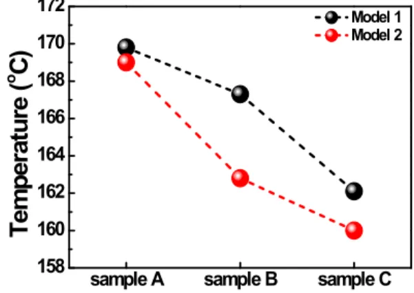
sample A sample B sample C 158
160 162 164 166 168 170 172
T e m p e ra tu re (
oC )
Model 1 Model 2