• 검색 결과가 없습니다.

Development of a 1500N-thrust Swirling-Oxidizer-Flow-Type Hybrid Rocket Engine

N/A
N/A
Protected

Academic year: 2021

Share "Development of a 1500N-thrust Swirling-Oxidizer-Flow-Type Hybrid Rocket Engine"

Copied!
6
0
0

로드 중.... (전체 텍스트 보기)

전체 글

(1)

Development of a 1500N-thrust Swirling-Oxidizer-Flow-Type Hybrid Rocket Engine

SAKURAZAWA Toshiaki

1

, KITAGAWA Koki

2

, HIRA Ryuji

1

, MATSUO Yuji

2

, SAKURAI Takashi

1

, YUASA Saburo

1,2

1. Tokyo Metropolitan University 2. Tokyo Metropolitan Institute of Technology

6-6 Asahigaoka Hino-City Tokyo, Japan [email protected]

Keywords: Hybrid Rocket, Swirling-Oxidizer-Flow, LOX Vaporization, Regenerative-Cooling Nozzle, PP

Abstract

We have been developing a 1500N-thrust Swirling- Oxidizer-Flow-Type hybrid rocket engine. In order to put the engine into practical use, we conducted long duration burning experiments up to 25s to examine the influence of configuration change of fuel grain on the engine performance and designed an LOX vapori- zation nozzle to supply GOX for the 1500N-thrust engine. The experiment with a small hybrid rocket engine showed that combustion was stable and the engine performance was approximately constant dur- ing combustion. There was no essential problem to with increasing combustion time. The LOX vaporiza- tion nozzle designed had 30 rectangular channels with a depth of 0.5mm. During passing through the nozzle, the LOX increased in temperature and vaporized suf- ficiently.

Background

Hybrid rocket engines with liquid oxygen and hy- drocarbon polymer compound as propellants excel in its propellant storage and delivery system, perfor- mance, cost, environmental impact and safety. How- ever, it is difficult to achieve the theoretical maximum specific impulse obtained in the fuel rich side due to low fuel regression rates. Therefore, hybrid rocket engines have not yet been used in practical rocket systems. In order to resolve this problem, we pro- posed a swirling-oxidizer-flow-type hybrid rocket engine, researched by using GOX (gaseous oxygen) and PMMA (polymethylmethacrylate) as propel- lants

1,2)

. In 2001, a small-scale hybrid rocket which had GOX/PMMA propellants and produced 700N of thrust was developed. The successful launch of the hybrid rocket was the first of its type in Japan

3,4)

.

As the next stage, we aim at the practical use of the hybrid rocket by which we can launch a small scale observation device in a high-altitude. In order to obtain same payload and altitude like the existing sounding rocket MT-135, a thrust of 3000N and a burning duration of 27.5s were required for the hybrid rocket engine. Currently, as part of the preliminary step, 1500N-thrust which is half the target thrust, and 30 seconds burning duration, nearly equal to the target

duration, a swirling-oxidizer-flow-type hybrid rocket engine has been developed.

Until now, the 1500N-thrust engine successfully achieved 10s burning duration using GOX/PMMA propellants

5)

. Furthermore, when the burning duration is increased, the swirling oxidizer flow, which inhe- rently causes the local fuel regression at the leading edge of the fuel grain, results in burn out of the fuel grain at the grain leading edge faster than the remain- ing fuel grain. This may affect the engine perfor- mance as well as the hybrid rocket. Then, for the pur- pose of investigating the effect of the fuel grain confi- guration change on engine performance when the combustion time increases, the experiments of long duration burning were carried out using a small hybr- id rocket engine, taking safety into combustion.

Meanwhile, in order to increase capacity of oxidiz-

er of hybrid rockets, researches on LOX (liquid oxy-

gen) use were conducted. When a swirling LOX was

directly injected into the combustion chamber, the

engine performance was lower than that of swirling

GOX

6)

. Hence, we decided to vaporize LOX before

injecting into the combustion chamber by the heat

exchange using a regenerative-cooled LOX vaporiza-

tion nozzle and made a small LOX vaporization noz-

zle, which fitted to our previous engine

2)

. The com-

bustion tests showed that LOX was safely vaporized

through the use of the LOX vaporization nozzle and

the performance of the swirling-oxidizer-flow-type

hybrid rocket engine increased

7)

. With these results,

an new LOX vaporization nozzle, which is fitted to a

1500N-thrust swirling-oxidizer-flow-type hybrid

rocket engine, was designed and constructed. In this

paper, above two points (a long duration burning of

the engine and an LOX vaporization nozzle) are re-

ported.

(2)

Long Duration Burning Experiment Using GOX/PP

A. Experimental Setup

a. Swirling-Oxidizer-Flow-Type Hybrid Rocket Engine

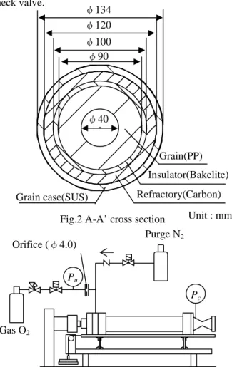
The schematic of the swirling-oxidizer-flow-type hybrid ocket engine used in this experiment is shown in Fig.1. Figure 2 shows the A-A’ cross-section in Figure.1. The engine used in the experiment was fun- damentally the same as a conventional engine and consists of an igniter, a swirling type injector, fuel grain, grain case, and a nozzle. The igniter was a commercial miniature solid rocket (propellant: black powder). The swirling type injector had 8 rectangle ejections, with the geometrical swirl number of Sg=19.7 indicating the strength of the swirling. The fuel grain was changed from PMMA to PP (polypro- pylene) with a higher theoretical specific impulse.

With increased combustion time, the leading edge of fuel grain may burn-out and the grain case may be exposed by high temperature burnt gas. Hence the outside circumference of the PP grain had a 5mm thick layer of Bakelite as a insulation and the further outside circumference of the leading edge particularly had a carbon layer as a refractory to protect the grain case. An adhesive was used to join the PP grain and Bakelite. The length of the fuel grain and grain case was variable within the range of 400-1000mm.

The focal point of this research was to investigate the effects of the grain leading edge burn-out. The engine used in the experiments had a PP grain in length of 600mm, and a thrust of approx. 300N. The nozzle was made from carbon and had an expansion ratio of 5.4 (for a thrust of 1500N). The combustion chamber pressure was measured at the nozzle inlet.

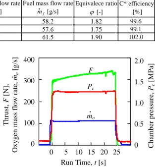
b. Experimental system

Figure 3 shows the schematic of the experimental system. It consisted of the swirling-oxidizer-flow- type hybrid rocket engine, the GOX supply system and the N

2

supply system. The mass flow rate of GOX was adjusted by setting the φ 4.0mm choking orifice and the GOX supplying pressure, P

u

. Burning experiments were carried out for the combustion times of 15, 20 and 25s. And the engine was purged with N

2

after test runs. To protect the N

2

supply line against an inflow of GOX, the N

2

supply line set a check valve.

Injector

Igniter Swirler Refractory(Carbon)

Insulator (Bakelite)

Nozzle (Carbon) Grain case

Grain (PP) Pressure Transducer Port

Fig.1 Schematic of 1500N-thrust Swirling-Oxidizer-Flow-Type hybrid rocket engine A-A’ cross section

600mm (400~1000) A

A’

P

c

P

u

Orifice (φ4.0)

Gas O

2

Fig.3 Schematic of experimental apparatus Purge N

2

φ90 φ100 φ120

φ40

Grain(PP) Insulator(Bakelite) Refractory(Carbon)

Unit : mm Fig.2 A-A’ cross section

φ134

Grain case(SUS)

(3)

B. Experimental results a. Engine Performance

Table 1 shows the experimental results. Under the oxygen mass flow rate was adjusted to be constant in each experiment, the experimental results were almost the same. As the time trace of the fuel mass flow rate could not be measured, the average fuel mass flow rate was calculated from the difference in mass of the fuel grain before and after the burning. The C* effi- ciency was calculated as the ratio of the experimental C* obtained from the average value of the propellant mass flow rate and combustion chamber pressure to the theoretical C* based on the equilibrium condition.

The C* efficiency of 99% or more was achieved for all the experiments. The C* efficiency of experiment No.3 exceeded the theoretical value. The cause of this is considered to be a pressure gradient formed in the radial direction by the centrifugal forces of the swirl- ing flow or an increase in combustion chamber pres- sure by the effect of decrease in effective surface area at the nozzle throat due to the development of a boun- dary layer at the nozzle

8, 9)

. In fact, when the C* effi- ciency was estimated including the effects of the swirling flow pressure gradient and the pressure in- crease due to the boundary layer effect, there is a pos- sibility that the experimental C* efficiency was over- estimated around 5%.

Figure 4 shows the typical traces of the gaseous oxygen mass flow rate, m

o

, the chamber pressure, P

c

, and the thrust, F, for the experiment No.3. It was found that ignition occurred rapidly and the combus- tion chamber pressure and the oxygen mass flow rate were mostly stable. However, the thrust increased as time progressed. The average values for the engine performance in this experiment were F = 319N, P

c

= 1.22MPa, m

o

= 110.6g/s, m

f

= 61.5g/s, ϕ = 1.90 and Isp = 188.7s. Since the nozzle used in this experiment was designed to have an optimum expansion ratio at the combustion chamber pressure of 4MPa, a small value for the specific impulse was obtained any from the experiments. In fact, the burning test used PP grain in 1000mm length and GOX at the combustion chamber pressure of 3.7MPa showed the engine per- formance of GOX mass flow rate: 387.5g/s, chamber pressure: 3.72MPa, thrust: 1419N, equivalence ratio:

1.86 and specific impulse: 241.7s.

Burning was generally stable however, at t=20s a small spike occurred in both the thrust and combus- tion chamber pressure. The cause for this was that when burning progressed to the bond surface of the grain and Bakelite, part of the grain peeled off and suddenly passed through the nozzle without burning.

An increase in fuel mass flow rate made it possible for the thrust to increase as time progressed. This is the supported by the following result and considera- tion. In the experiments, the oxygen mass flow rate and combustion chamber pressure were mostly stable.

As the fuel mass flow rate increased due to the grain surface area becoming larger with the progression of time, the equivalence ratio increased making the en- gine performance drop but the thrust increase. From the experiments, increasing the burning duration of the swirling-oxidizer-flow-type hybrid rocket engine had no intrinsic problems and it could be operated without large change of engine performance over time.

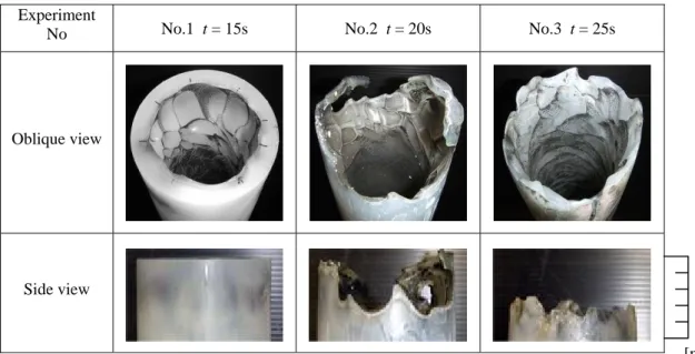
b. Configuration Change of Fuel Grain

Figure 5 shows the appearance of the grain after the experiments. For the grain of the experiment No.1, which was the shortest burning duration condition, it was identified that large deep depressions interspersed with small shallow depressions corresponding to the number of swirler holes within a region 20mm from the leading edge of the grain. For the grain of the experiment No.2, with the next longest burning dura- tion, more than 50% was burnt out and only a partial amount of the grain remained in a 30mm section from the leading edge.

Table 1 Experimental results (Average)

・ ・

1 15 301 1.17 109.1 58.2 1.82 99.6

2 20 314 1.18 112.3 57.6 1.75 99.1

3 25 319 1.22 110.6 61.5 1.90 102.0

C* efficiency [%]

Fuel mass flow rate m

f

[g/s]

Equivalece ratio ϕ [-]

Thrust F [N]

Experiment No

Run time t [s]

Chamber Pressure P

c

[MPa]

Oxygen mass flow rate m

o

[g/s]

Run Time, t [s]

0 5 10 20 15 25 Chamber press u re , P [M Pa]

c

2.0 1.5 1.0 0.5 0 400

300 200 100 0 Thrust, F [N ], Oxygen mass f low rate, m

o

[g /s]

Fig.4 Time trace of engine parameter F

P

c

m

o

・ ・

(4)

Then for the grain of the experiment No. 3, with the longest burning duration, 30mm from the grain lead- ing edge of the grain was completely burnt-out. From this result, it was found that between t=15-25s, burn out of the grain leading edge of the grain occurred.

The Bakelite positioned around the grain had car- bonized its surface in experiments No. 1 and No. 2, and was partially burnt out in experiment No. 3.

However, the carbon positioned around the Bakelite appeared to be completely untouched by burning and was confirmed to be extremely effective as fire proof- ing.

In addition, partial burn-out on the injector surface joining the fuel grain was confirmed. This partial burn-out of the stainless steel injector was considered to be from exposure to high temperature oxygen rich gas when the fuel grain touching the surface of the injector burnt out. Hereafter, it is necessary to set refractory between the injector and the grain.

c. Local Fuel Regression Rate

Figure 6 shows the local fuel regression rate, r, against distance from the grain leading edge, x, for the experiments No. 1-3 measured after combustions.

However, for the experiment No. 3, there were no values for the burnt out part 40mm from the grain leading edge of the fuel grain omitted. For all the ex- periments, the local fuel regression rates between x=0-100mm was comparatively large, and it de- creased as x increased, and from x=100mm even as x increased downstream, it remained mostly constant.

Also, even if the burning duration increased, from x=100mm and downstream, the local fuel regression rates were independent of the burning duration.

Generally, the relationship between the fuel regres- sion rate, r, and distance, x, of hybrid rocket engines without swirling can be theoretically approximated in the following formula, r=CG

0.8

x

-0.2

, where C is a con- stant and G is propellant mass flux

9)

.

This formula contains two effects. One is that the boundary layer becomes thicker downstream and the amount of heat transferred decreases, resulting in de- crease of the fuel regression rate. The other is that as the mass of burnt fuel is increased in going down- stream, the propellant mass flux, G, becomes larger and the increasing flow velocity decreases the boun- dary layer thickness, resulting in increase of the heat transferate and fuel regression rate. Whereas in the case of swirling oxidizer flow, it is considered that the local fuel regression rate gets smaller with increasing x due to swirling flow becoming weaker as the cir- cumferential velocity component decreases due to frictional resistance or additional fuel without angular momentum.

Experiment

No No.1 t = 15s No.2 t = 20s No.3 t = 25s

Oblique view

Side view

30 0

50 20 40 10

[mm]

Fig. 5 Appearance of grain leading edge after combustions

Local Fuel Re gres sion Rate, r [m m/s]

Distance from the Grain Leading Edge, x [mm]

0 100 200 500 300 400

2.0

0.8 0.4 0

Fig.6 Axial profiles of local fuel regression rate 600 1.2

1.6

t = 15s t = 25s t = 20s

(5)

From the above discussion and the appearance of the grain after combustion, it is considered that in the region near the grain rim that has the most influence from swirling, as a result of the formation of imping- ing jet flames between the grain surface and the swirl- ing oxygen jets, there are large deep depressions cor- responding to the number of swirler holes. Adjoining those are comparatively small and shallow depres- sions in the region of x=20mm. These configurations increase the fuel regression rate locally. These swirl- ing oxygen jets get caught up the regional flow and fuel in further downstream and make complex surface flows. However, the velocity distribution of the swirl- ing flow becomes uniform downstream, which makes the depressions shallow and in turn, the local fuel regression rate, r becomes small. In fact, these de- pressions can be seen up to x=100mm, and further downstream the combined effects of boundary layers and angular momentum mentioned above causes the fuel grain to be consumed uniformly, even if the burn- ing duration is increased.

Design of the Lox Vaporization Nozzle The LOX vaporization nozzle is made from oxygen free copper which has a high thermal conductivity and constructed as a single piece by electroforming. The nozzle was designed using an in-house program as- suming one-dimensional steady-state thermal balance in the nozzle

10, 11)

. Figure 7 shows a calculation mod- el. This program calculated the thermal equilibrium in the direction of flow of the oxygen for vaporization at the steady-state along delimited sections of 10µm intervals (i) along the nozzle in the axial direction considering the heat convection, h

g

, between the burnt gas at the fixed state (T

g

) – the inner nozzle wall (T

wg

); the heat conduction, k, between the inner nozzle wall (Twg) – the lower surface of the channel (T

wo

);

and the heat convection, h

o

, between the lower surface of the channel (T

wo

) – the oxygen flow for vaporiza- tion (T

o

). Here, the corrected Bart’z equation

12)

was used for the heat transfer coefficient between the burnt gas and the nozzle inner wall, and the Sieder- Tate’s equation

8)

, relating to the turbulent heat trans- fer in a tube, was used for the heat transfer coefficient between the channels internal wall and oxygen. The nozzle design parameters are follows: thrust: 1500N, combustion chamber pressure: 4MPa, throat diameter, φ:17.8mm, expansion ratio: 5.67, LOX supply pres- sure: 4.5MPa, LOX mass flow rate: 385g/s, and num- ber of channels for oxygen: 30.

i+1 i i-1

T

oi

T

oi-1

T

oi+1

T

gi

h

oi

h

gi

k

i

Burnt gas T

wg

T

wo

Inner wall Outer wall

Fig.7 Model of heat transfer analysis Channel Oxygen

LOX temperat ure , T

o

[K ]

Fig.8 Thermal analysis results 30

Distance from throat, x [mm]

Heta fl ux, q [MW /m

2

]

40

20 10 0 50 800

1000

600 400 200

0 -80 -60 0 -40 20 -20 40 60 T

wg

T

o

q

Nozzle wall tempe rature , T

wg

[K ]

P

o

Inlet Outlet

LOX press u re, P

o

[M Pa]

Table 2 Thermal analysis results Cross section

area [mm

2

]

LOX flow velocity [m/s]

LOX heat transfer coefficient [kW/m

2

K]

LOX pressure [MPa]

LOX temperature [K]

2 2.3 6.9 17.4 4.52 223 1054

1 1.2 14.2 32.1 4.57 242 903

0.5 0.6 29.9 61.3 4.70 268 767

Channel depth[mm]

Throat (x = 0) Channel outlet (x = -73.3)

Max nozzle wall temperature [K]

φ 86 φ 42 .4

Fig.9 LOX vaporization nozzle

φ 17 .8

30 15 GOX

LOX

Unit : mm 132.9

Wall temperature measured

(6)

A counter-flow method is used in which the oxygen flow is in the opposite direction to the flow of the burnt gas. Table 2 shows, as a parameter of channel depth, the analytical results of the maximum nozzle wall temperature, T

wg

and the state of the oxygen at the flow outlet, and Fig. 8 is a graph showing the noz- zle wall temperature, T

wg,

the temperature and pres- sure of the oxygen (T

o

, P

o

) and the inflowing heat flux, q, as a function of axial distance along the nozzle with a channel depth of 0.5mm. In Fig. 8, x=-73.3 is the flow outlet, x=0 is the nozzle throat and x=40 is the flow inlet. In Table 2, as the channel becomes shal- lower, the nozzle wall temperature, T

wg

, becomes lower and the oxygen temperature, T

o

, at the flow outlet becomes higher. This is due to faster oxygen flow velocities in the channel with a small cross sec- tional area and the heat transfer coefficient between the channel wall and the oxygen becoming larger.

Hence, the nozzle vaporization capability is high as the channel becomes shallow. From this results and based on the analytical results shown in Fig. 8, the 0.5mm channel depth 1500N-thrust LOX vaporization nozzle shown in Fig. 9 was designed and is currently under construction.

Hereafter, an experiment is scheduled using the 1500N-thrust swirling-oxidizer-flow-type hybrid rocket engine fitted with the LOX vaporization nozzle shown in Fig. 9.

Conclusion

9 Long burning experiment of 25s was carried out in which the leading edge of the grain was burnt- out, and even if the grain shapes changes, there are no large influences in engine performance independent of burning duration.

9 At the grain leading edge, local fuel regression rate vastly increased due to the formation of im- pinging jet flames by swirling oxygen flow.

Downstream from x=100mm, local fuel regres- sion rate was constant regardless of burning du- ration.

9 At the grain leading edge, part of the Bakelite insulator was burnt out but the carbon was ex- tremely effective as fire-proofing.

9 A 1500N-thrust regenerative-cooled LOX vapo- rization nozzle with 30, 0.5mm deep channels was analyzed and designed that can bring LOX up to 268K, sufficiently vaporizing it.

Acknowledgement

This work was supported in part by the University Space Engineering Consortium (UNISEC 2007 Project Support) and JAXA/ISAS sounding hybrid rocket research program. Also, when conducting the experiments, a great deal of cooperation was received from Ms. Ikuno Kumazawa., Ms. Yukari Shuto., and Mr. Takeshi Matsui. We would like to give our thanks to everyone involved in this venture.

Reference

1) Yuasa, S., et al.: A Technique for Improving the Performance of Hybrid Rocket Engines, AIAA Paper 99-2322,1999.

2) Tamura, T., et al.: Effects of Swirling Oxidizer Flow on Fuel Regression Rate of Hybrid Rockets, AIAA Paper 99-2323, 1999.

3) Yuasa, S., et al.: Development of a Small Sound- ing Hybrid Rocket with a Swirling-Oxidizer- Type Engine, AIAA Paper 2001-3537, 2001.

4) Kitagawa, K., et al.: Development and Experi- mental Launch of Small Hybrid Rocket with a Swirling-Oxidizer Type Engine, ISTS Paper 2002-g-20, 2002.

5) Kitagawa, K., et al.: Research of a Swirling Oxi- dizer Type Hybrid Rocket Engine for a High Al- titude Rocket, the 49th Space Sciences and Technology Conference, 1G03, 2005.(Japanese) 6) Kitagawa, K., Yuasa, S.: Combustion Characte-

ristics of a Swirling LOX Type Hybrid Rocket Engine, JJSASS, Vol 54(2006), pp.242-249.

(Japanese)

7) Kitagawa, K., et al.: Combustion Experiment and Evaluation of a LOX Vaporization Nozzle for Swirling-Oxidizer-Flow-Type Hybrid Rocket Engines, AJCPP, 2007. (Japanese)

8) ITSURO, K.: Roketto Kougaku, (Rocket engi- neering, Yokendo Co., Ltd., Japan, pp.118-119,

pp.258-260, 1993.(Japanese)

9) G. P. Sutton.: Rocket Propulsion Elements 6th ed, Wiley Interscience, America, pp. 73-74, pp506- 511.

10) Kitagawa, K., et al.: Combustion Experiment to Evaluate a LOX Vaporization Nozzle for a Swirling-Oxidizer-Flow-Type Hybrid Rocket Engine with a 1500N-Thrust, STJ, Vol.6(2007), pp.47-54.(Japanese)

11) Ro, T., et al.: The Design of Regenerative Cool- ing Nozzle with Liquid Oxygen for Hybrid Rocket Engine, AJCPP, 2004. (Japanese) 12) Yatsuyanagi, N., et al.: A Study of Liquid Hy-

drogen Cooled LO2 / LH2 Rocket Combustor with Slotted Wall Liner (1), NAL TR-679, 1981.

(Japanese)

수치

Figure 3 shows the schematic of the experimental  system.  It consisted of the  swirling-oxidizer-flow-type hybrid rocket engine, the GOX supply system  and the N 2  supply system
Table 1 shows the experimental results.  Under the  oxygen mass flow rate was adjusted to be constant in  each experiment, the experimental results were almost  the same
Figure 6 shows the local fuel regression rate, r,  against distance from the grain leading edge, x, for the  experiments No
Table 2 Thermal analysis results  Cross section

참조

관련 문서

The “Asset Allocation” portfolio assumes the following weights: 25% in the S&P 500, 10% in the Russell 2000, 15% in the MSCI EAFE, 5% in the MSCI EME, 25% in the

1 John Owen, Justification by Faith Alone, in The Works of John Owen, ed. John Bolt, trans. Scott Clark, "Do This and Live: Christ's Active Obedience as the

The thickness of crose-sectional is decreased, the roughness of top surface is decreased as a function of the oxygen gas flow rate was increased.. The structure and

Determined parameters was used for the implementation of side-processed POF with the CO 2 laser, and measured experimental results of the illumination proved

~ The streak lines can be used to trace the travel of a pollutant downstream from a smoke stack or other discharge. ~ In steady flow, Lagrangian path lines are the same as

Using selected engine performance simulation results as input to the intake faces of the nozzles and ejector CFD simulation to determine pressure loss, temperature levels and

In gi ngi va,LCs are found i n oralepi thel i um ofnormalgi ngi va and i n smal l er amountsi nthesul cul arepi thel i um,buttheyareprobabl yabsentfrom thejuncti onal epi thel

Based on the experimental results, the execution time in the matching process for 36 fingerprint minutiae, 200 chaff minutiae and 34 authentication fingerprint